Njoy SNMP Card PM Lite User manual

SNMP Card PM Lite
User manualACUP-SN000MP-CG01B
Before using this product, carefully read all product documentaon and retain it for future reference.
151.0

2 3
Thank you for purchasing our products!
Please read this manual before using the product.
Focusing on quality at compeve prices, nJoy designs
consumer products for a beer and enjoyable way into
the digital world.
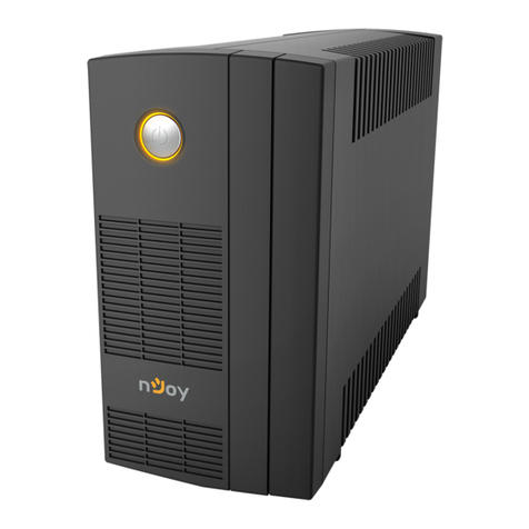
This UPS will protect your electronic equipment from physical
damage and will provide emergency baery backup power to
prevent data loss in the event of power problems.
Table of contents
EN
1. Package contents ................................................................................................... 3
2. Product overview ................................................................................................... 4
2-1. Front Panel .................................................................................................... 4
2-2. LED Status Indicators ................................................................................. 4
3. Installaon ................................................................................................................ 5
4. Web Interface .......................................................................................................... 8
4-1. Login User Account ..................................................................................... 8
4-2. Reset to Factory Default Seng / Recover from a Lost Password ..... 9
5. Troubleshoong .................................................................................................... 10
Package contents1
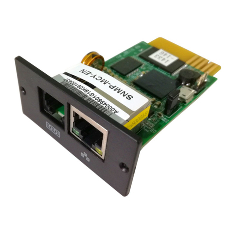
PM card
Spare jumper
User Manual
NOTE!
If any of the above package content is missing or is damaged please contact the
shop where you have bought the product from.
nJoy UPS models that are compable with this product:
Aster Series
Argus Series
Echo Pro Series
1K / 2K / 3K
1.2K / 2.2K / 3K
1K / 2K / 3K

4 5
Product overview2
2-1. Front Panel
PMCARD
1. Universal port
2. Ethernet Port
3. Tx/Rx Indicator
4. Link Indicator
2-2. LED Status Indicators
Link LED Condion
O The Power Management Card is not connected to the
Network/ or the Power Management Card power is o
On (Yellow) The Power Management Card is connected to the
Network
Tx/Rx LED
O The Power Management Card power is o
On (Green) The Power Management Card power is on
Flashing (Green) Receiving/transming data packet
Reset nished
Installation3
Step 1. Hardware Installaon
1. Remove the two retaining screws from the expansion slot and remove the
cover.
2. Install the Power Management Card into the expansion slot.
3. Insert and ghten the retaining screws.
4. Connect an Ethernet cable to the Ethernet port of the Power
Management Card.
PMCARD
NOTE!
The Power Management Card is hot-swappable, so you do not need to turn off the
UPS to install it.
Step 2. Congure the IP address for the Power Management Card
Method 1: Using the Power Device Network Ulity
1. Install the Power Device Network Ulity available for download at
hp://www.powermonitor.soware/#PowerDeviceSoware.
2. Aer installaon completes, run the “Power Device Network Ulity”.
3. The main window of the Power Device Network Ulity program is shown
in Figure 1. The conguraon tool will display all Power Management
Card devices present on the local network subnet. The “Refresh” buon is
used to search the local network subnet again.

6 7
Figure 1. The main window of the “Power Device Network Utility” program.
4. Select the Power Management Card you are seng up. Click on the Tools
menu and select “Device Setup” or double click the device you want to
congure.
5. You can modify the IP Address, Subnet Mask, and Gateway address for
the Device MAC Address listed in the Device Network Sengs window,
as shown in Figure 2. The factory default IP Address is 192.168.20.177
and the default Subnet Mask is 255.255.255.0.
Figure 2. The Device Network setting window.
6. Modify the IP, subnet mask or gateway address. Enter the new addresses
into the corresponding elds and then click “Save”.
7. You will need to enter a User Name and Password for the Power Manage-
ment Card in the authencaon window, as shown in Figure 3.
Default user name: admin
Default password: admin
Figure 3. Authentication window.
8. If the IP address change is successful, you will see a message conrming
the IP set up is OK, as shown in Figure 4.
Figure 4. Setup IP Address successfully message.
9. In case the change is not successful, for example, if the IP address
change is unsuccessful you will see a warning message. Aempt to
make the desired changes again. If the problem persists please see the
Troubleshoong secon for help.

8 9
Method 2: Using a command prompt
1. Obtain the MAC address from the label on the Power Management Card.
Each Management Card has a unique MAC address.
NOTE!
The MAC address is labelled on the card.
2. Use the ARP command to set the IP address.
Example:
To assign the IP Address 192.168.10.134 for the Power Management
Card, which has a MAC address of 00-0C-15-00-FF-99 you will type in
the following in the command prompt from a PC connected to the same
network as the Power Management Card.
(1) Type in “arp -s 192.168.10.134 00-0C-15-00-FF-99” for Windows OS;
type in ”arp –s 192.168.10.134 00:0c:15:00::99” for Mac OS, then
press Enter.
3. Use the Ping command to assign a size of 123 bytes to the IP.
(1) Type in “ping 192.168.10.134 -l 123” then press Enter.
(2) If the replies are received, your computer can communicate with the IP
address.
To select an available IP address for the Power Management Card, please
refer to Appendix 1.
Web Interface4
4-1. Login User Account
You will need to enter a User Name and Password to login to the interface
There are two user account types.
1. Administrator
Default user name: admin
Default password: admin
2. View only
Default username: device
Default password: device
You will be asked to reset a username and password upon the rst login. The
administrator can access all funcons, including enable/disable the view only
account. The viewer can access read only features but cannot change any
sengs.
NOTE!
1. The Administrator account is also used for the FTP login and Power Device
Network Utility.
2. Only one user can log in and access the device at a time.
4-2. Reset to Factory Default Seng / Recover from a Lost Password
To reset the Power Management Card to its factory default seng (including
web log-in user name and password), please following these steps:
PMCARD
1. Remove the card from the UPS without turning the UPS o.
2. Remove the jumper from the reset pins as illustrated. Do not dispose of
the jumper.
3. Insert the card into the expansion port on the UPS.
4. Wait unl the green Tx/Rx LED is ashing (the frequency of the ON/OFF
ashing is once per second).
5. Remove the card again.
6. Place the jumper back onto the Reset pins.
7. Install card into the expansion port again and ghten the retaining screws.

10
Troubleshooting5
Problem Soluon
Unable to congure
the Power
Management Card
using method 1 or
method 2
1. Check the LED status, it is normal when the
yellow and green LEDs are both on.
If green LED is o:
Check if the Power Management Card is
properly seated in the device and the device
has power.
If yellow LED is o:
Ensure the network connecon is good.
2. Ensure the PC being used is on the same local
network subnet as the device you are trying to
communicate with.
3. Ensure the Jumper on the Reset Pin is correctly
installed.
Unable to ping
the Power Manage-
ment Card
1. Use method 1 and/or method 2 to get/set a
correct IP address for the Power Management
Card.
2. If the PC being used is on a dierent network
subnet from the Power Management Card, veri-
fy the seng of subnet mask and the IP address
of gateway.
Lost the user name
and password
Please refer to the “Reset to Factory Default Set-
ng / Recover from a Lost Password” secon.
Default Network
Seng
IP: 192.168.20.177
Subnet mask: 255.255.255.0 DHCP: On
Unable to access
the Web Interface
1. Ensure you can ping the PMCARD.
2. Ensure you are specifying the correct URL.
Unable to operate
a SNMP get/set
SNMPv1: Verify the community name.
SNMPv3: Verify the user prole conguraon.
Unable to receive
traps
1. Ensure the trap types (SNMPv1/SNMPv3) and
trap receiver are congured correctly.
2. Ensure the IP address of gateway is congured
correctly if the PMCARD and NMS are on a
dierent network.
Disposal of Old Electrical & Electronic Equipment
(Applicable in the European Union and other European countries with
separate collecon systems)
This symbol on the product or on its packaging indicates that this product shall
not be treated as household waste.
Instead it shall be handed over to the applicable collecon point for the recycling
of electrical and electronic equipment.
By ensuring this product is disposed of correctly, you will help prevent potenal
negave consequences for the environment and human health, which could
otherwise be caused by inappropriate waste handling of this product.
The recycling of materials will help to conserve natural resources.

This manual suits for next models
1
Table of contents
Other Njoy Computer Hardware manuals
