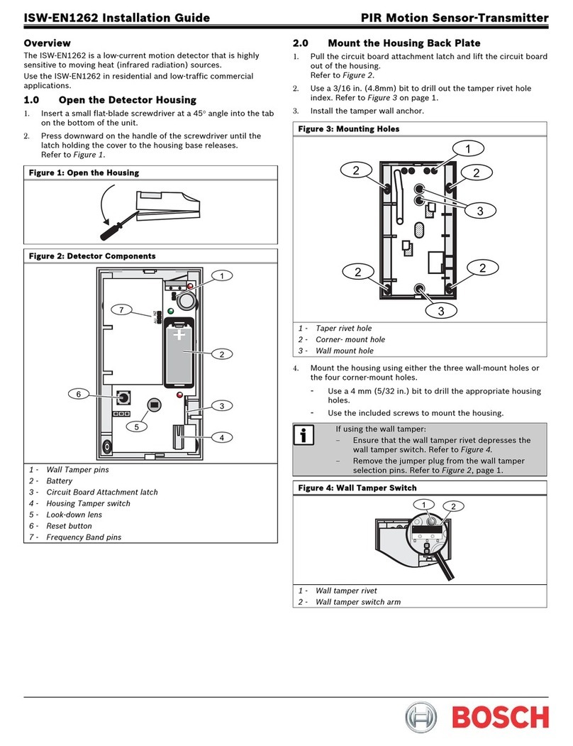
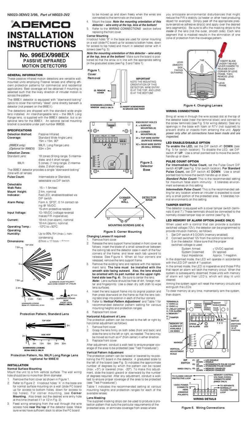
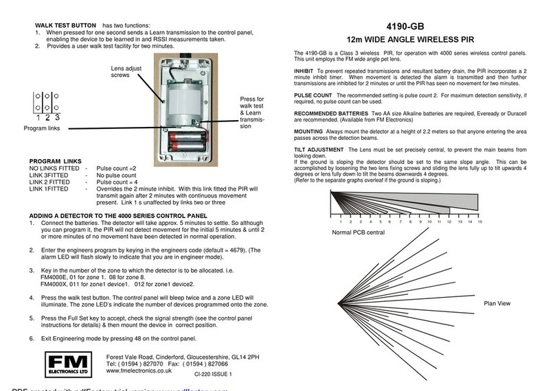
Datasensing S3N-PR T5 Series User manual

T51
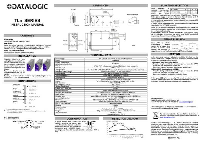
GENERAL CONTROLS
Se
nsitivityadjus
t
T
51:Stability
Yellow LED
:
Output status
Sing
l
etrimmer Mo
d
e
l
s
L/Dselection
Sensitivityadjus
t
T
51: 1 turn
GreenLED
:
T51:Stability
Yellow LED
:
Output status
Dual trimmerModels
T5
1: 1 turn
Green LED:
T53
Teach Button (T53)
Performs all User interface interactions.
Output LED
The yellow LED indicates the output status.
Stability LED (T51)
The green LED ON indicates that the received signal has a safety
margin greater than 20% compared to the output switching value.
Power On LED (T53)
The green LED indicates that the sensor is operating.
Sensitivity Knob (T51)
The trimmer can be used to adjust sensitivity; the operating distance
increases turning the trimmer clockwise.
IO-Link Activity LED (T53)
The Blue light is on during IO-Link data exchange.
Dark/Light Trimmer (T51)
This trimmer can be used to set LIGHT or DARK operation mode.
CAUTION: The trimmer rotation is limited to 250° by a mechanical stop.
Do not apply excessive torque when adjusting (max 0.02 Nm).
DIMENSIONS
NOTE: “A” and “B” values in the following drawing are indicated in the
“Optical Interaxes” table.
M8x1
Emitter
Receiver
10.8
21.1
42.3
A
B
3,4
M3 X2
11.6
31.5
25.4
19.5
5.2
Optical Interaxes
Version A B
S3N-PR-X-T5X-XX 0 17.2
CONNECTIONS
T51 (PNP) T51 (NPN)
T53 M8 CONNECTOR
BLACK 4 C/Q
BROWN 1 +10...30VDC
BLUE 3 0V
WHITE 2 NPN/PNP OUT
BLACK 4 PNP OUT
BROWN 1 +10...30VDC
BLUE 3 0V
WHITE 2 N.C.
BLACK 4 NPN OUT
BROWN 1 +10...30VDC
BLUE 3 0V
WHITE 2 N.C.
2
1
4
3
INSTALLATION
The sensor can be positioned by mean of the two threaded holes
(M3) using two screws (M3x12 or longer, or M2.5 passing screw +
nuts) and relative washers. Maximum tightening torque is 0.5Nm.
Various brackets are available to ease the sensor posiitoning (please
refer also to accesories listed in the catalogue).
Mounting Bracket (various options)
Mounting screws
M3X12 or longer (screwing)
M2.5x12 or longer (passing)
806000670 Rev. A ENG Ed 02/2023
Datasensing S.r.l.
Strada S. Caterina 235 - 41122 Modena - Italy
Tel. +39 059 420411 - Fax +39 059 253973
web: www.datasensing.com
email: [email protected]
S3N-PR...T5X
POLARIZED RETROFLEX FOR TRANSPARENT OBJECTS
Safety Precautions
Read the precautions for all models at http://www.datasensing.com.
WARNING: This product is not designed or rated to ensure personal safety either
directly or indirectly. Do not us it for such purposes.
WARNING: Do not exceed the rated voltage. There is a possibility of failure and
fire.
CAUTION: Do not use this product above its IP protection ratings. Failing to do so
may damage its components.
CAUTION: DC models shall never be used with AC mains power supply. Failing to
do so may result in explosions or other damage.
CAUTION: Do not disassemble this product. Doing so may cause exposure to the
built-in light source which can damage eyes and skin. Never disassemble it.
TECHNICAL DATA
S3N-PR-T51 S3N-PR-T53
Power Supply: 10-30 Vdc; reverse polarity protected
Ripple: p-p 10% max.
Current
consumption ≤35mA (≤55mA below 15V supply)
Output: IO-Link (Pin 4) + configurable I/O (Pin 2)
Output current: 100 mA max. short circuit protected
Saturation voltage: 2 V max.
Response time: 0.5 ms 1 ms
Switching
frequency: 1 kHz 500 Hz
Indicators Yellow: output status
Green: Stability Yellow: output status
Green: power on
Blue: IO-Link activity
Setting: Sensitivity: 1 turn trimmer
L/D selection (-P, -N models only) Setting distance, L/D configuration, special
functions by Teach button or IO-Link confi-
guration (see settings table)
Operating
Temperature: -25°C…55°C (not condensing)
Storage
Temperature: -40 … +70 °C
Operating distance: 0...2 m (R7)
Emission Type: Red LED 635nm EC 62471 EXEMPT RISK GROUP (RG0)
Ambient light rejection: According to 60947-5-2 plus reinforced immunity (internal test)
Vibration: 0.5 mm amplitude, 10 … 55 Hz frequency, for each axis (EN60068-2-6)
Shock resistance: 11 ms (30 G) 6 shock for each axis (EN60068-2-27)
LIGHT/DARK selection: By selector on -N and -P models.
By purchasing code on other models By teach button or IO-Link configuration
PNP/NPN Output: Selection by purchasing order Configurable through IO-Link configuration
Housing: Body: Glass filled technopolymer
Indicators: TPE
Actuators: POM
Lenses: PMMA
Protection class: IP67
Connections: On S3N-PR-2-xxxx: 3 poles cable Ø3.5mm;
On S3N-PR-5-xxxxx M8 connector 4 poles
Weight: 50 g. max. cable versions /
10 g. connector versions
95ACC0024
95ACC0025
95ACC0026

TEACH MODE FUNCTIONS
Push and hold for... 1s 3s 6s 20s Button release
Function Idle Teach1 Teach2 Teach3 Teach6 Idle
Visual Feedback
Green LED on Green LED off Green LED on Green LED off Green LED on Green LED on
S3N-PR-X-T53 Idle Standard Teach (transpa-
rent object) Teach Translucent Object L/D Select (Toggle) Restore factory settings Idle
T51 SETTINGS
S3N-PR-X-T51-XX
Position the sensor and reflector on opposite sides of the desired
sensing range. Turn the sensitivity trimmer to maximum. Adjust the
direction of the sensor in the middle of the angular sensing range.
To perform this procedure, look at the spot on the reflector from the
back of the sensor in the direction of the beam, and ensure that the
spot is entirely contained inside the reflector. Alternatively, find the
angles where the yellow LED (OUT) is switched ON and OFF in both
vertical and horizontal directions, and fix the sensor at the center
between these angles.
Adjust sensitivity to match your application requirements (described
below for dark on output):
- Turn the sensitivity knob counterclockwise until the sensor turns
ON
- Slowly turn the sensitivity knob clockwise until the sensor turns
OFF
- Fine adjust the sensitivity knob while testing detection to find the
best compromise for your application: turning counterclockwise
decreases the stability of the detection and increases the transpa-
rent detection capability, and vice versa. For best performance, a
good quality reflector with small prism is recommended (such as
R7). The optimal operation result is obtained when the green LED
turns ON. If you bought a model with DARK/LIGHT adjustment
capability (dual trimmer on user interface), adjust th L/D function to
match your application requirements.
T53 SETTINGS
S3N-PR-X-T53-XX
Position the sensor and reflector on opposite sides of the desired
sensing range, and execute the desired Teach Procedure.
Teach1 (Standard Teach for Transparent Object): the sensor
sets the threshold 8% below the signal measured from the reflector.
Teach 2 (Teach Translucent Object): the sensor sets the thre-
shold 12% below the signal measured from the reflector.
Teach 3 (Toggle L/D behavior): sensor behavior toggles between
Light ON and Dark ON modes.
Settings through IO-Link: the above teach procedures may also be
initiated through IO-Link. Furthermore, fine regulation of sensitivity
can be performed by changing sensitivity parameters.
S3N-PR-X-T5X-XX max. operating distance table (m)
Available Reflectors
R1 R2 R3 R4 R5 R6 R7
2.5 3.5 2.0
TEACH MODE
The selection of the desired teach mode and adjustment of the sen-
sor is performed by pressing the TEACH (T) button and observing the
green LED behavior; each time the LED toggles a new teach mode
is selected.
Once a teach mode is selected, it may be confirmed by releasing the
TEACH button within 3s from selection. Otherwise, if the TEACH
button is held for more than 3s aer teach mode selection, the teach
mode is discarded and next one (if available) is selected.
Holding the TEACH button until last available teach mode is discar-
ded will result in factory reset.
In case of error during the teach procedure (e.g. trying to perform
teach outside the operating range), the yellow LED will flash an error
status. The error can be canceled by pushing and releasing the teach
button. The sensor is reverted to the previous status before the error.
TEACH CONTROLS
Teach Button
Teach Button can be used to change the L/D function of the sensor,
or to execute different teach modes.
U.I Interaction
The green LED toggles to indicate advancement of the procedure to
next step.
Error Indicator
The yellow LED may flash in the event of a teach error.
©2023 Datasensing S.r.l.
• All rights reserved • Without limiting the rights under copyright,
no part of this documentation may be reproduced, stored in or
introduced into a retrieval system, or transmitted in any form or by
any means, or for any purpose, without the express written permission
of Datasensing S.r.l. • Datasensing and the Datasensing logo are
trademarks of Datasensing S.r.l.
See www.patents.datasensing.com for patent list.
This product is covered by one or more of the following patents:
Utility patents: IT102015000057325, IT102017000151097,
US10823878, US11146425, US11163090.
IO-LINK PARAMETERS
To download the IO-Link parameters, click or scan the QR code below.
S3N-T53
On bag label
WHERE TO FIND YOUR PRODUCT MODEL NAME
S3N-PR-5-T53-OZ
Made in XXXXX SYYWW
On product

T51
ALLGEMEINE KONTROLLEN
Se
nsitivityadjus
t
T
51:Stability
Yellow LED
:
Output status
Sing
l
etrimmer Mo
d
e
l
s
L/Dselection
Sensitivityadjus
t
T
51: 1 turn
GreenLED
:
T51:Stability
Yellow LED
:
Output status
Dual trimmerModels
T5
1: 1 turn
Green LED:
Teach-Taste (T53)
Führt alle Interaktionen der Benutzeroberfläche durch.
Ausgangs-LED
Die gelbe LED gibt den Status des Ausgangs an.
Stabilität-LED (T51)
Das Aufleuchten der grünen LED zeigt an, dass das empfangene
Signal eine Sicherheitsspanne von mehr als 20 % gegenüber dem
Ausgangsschaltwert aufweist.
Power-LED (T53)
Die grüne LED zeigt an, dass der Sensor in Betrieb ist.
Knopf für die Empfindlichkeitseinstellung (T51)
Der Trimmer kann zur Einstellung der Empfindlichkeit verwendet
werden; durch Drehen des Trimmers im Uhrzeigersinn wird der
Arbeitsabstand erhöht.
IO-Link-Aktivitäts-LED (T53)
Das blaue Licht leuchtet während des IO-Link-Datenaustauschs.
Trimmer dunkel/hell (T51)
Mit diesem Trimmer kann der Betriebsmodus HELL oder DUNKEL
eingestellt werden.
WARNUNG: Die Drehung des Trimmers ist durch einen mechanischen
Anschlag auf 250° begrenzt. Bei der Einstellung kein übermäßiges
Drehmoment anwenden (max. 0,02 Nm).
ABMESSUNGEN
HINWEIS: Die Werte „A“ und „B“ in der folgenden Zeichnung sind in der
Tabelle „Optikabstand“ angegeben.
M8x1
Emitter
Receiver
10.8
21.1
42.3
A
B
3,4
M3 X2
11.6
31.5
25.4
19.5
5.2
Cable output detail
Ø3.5
Optikabstand
Version A B
S3N-PR-X-T5X-XX 0 17,2
ANSCHLÜSSE
T51 (PNP) T51 (NPN)
T53 STECKVERBINDER M8
BLACK 4 PNP OUT
BROWN 1 +10...30VDC
BLUE 3 OV
WHITE 2 N.C
BLACK 4 NPN OUT
BROWN 1 +10...30VDC
BLUE 3 0V
WHITE 2 N.C.
BLACK 4 C/Q
BROWN 1 +10...30VDC
BLUE 3 0V
WHITE 2 NPN/PNP OUT
2
1
4
3
INSTALLATION
Der Sensor kann über die beiden Gewindelöcher (M3) mit zwei Schrauben (M3x12 oder länger, oder M2,5 Durchgangsschraube + Muttern) mit
den entsprechenden Unterlegscheiben befestigt werden. Das maximale Anzugsdrehmoment beträgt 0,5Nm.
Zur einfacheren Positionierung des Sensors sind verschiedene Montagewinkel verfügbar (auch Bezug auf das im Katalog aufgeführte
Zubehör nehmen).
Mounting Bracket (various options)
Mounting screws
M3X12 or longer (screwing)
M2.5x12 or longer (passing)
95ACC0024
95ACC0025
95ACC0026
806000670 Rev. A DEU Ausg. 02/2023
Datasensing S.r.l.
Strada S. Caterina 235 - 41122 Modena - Italien
Tel. +39 059 420411 - Fax +39 059 253973
web: www.datasensing.com
email: [email protected]
S3N-PR...T5X
POLARISIERTER RETROFLEX FÜR
TRANSPARENTE OBJEKTE
Sicherheitsvorkehrungen
Die Sicherheitsvorkehrungen für alle Modelle auf der Seite
http://www.datasensing.com lesen.
ACHTUNG: Dieses Produkt ist weder direkt noch indirekt für die Sicherheit von
Personen konzipiert oder ausgelegt. Nicht für solche Zwecke verwenden.
ACHTUNG: Die Nennspannung darf nicht überschritten werden. Gefahr von
Ausfällen und Bränden.
WARNUNG: Dieses Produkt nicht über seiner IP-Einstufung verwenden. Die
Nichtbeachtung dieser Sicherheitsvorkehrungen kann zu einer Beschädigung der
Bauteile führen.
WARNUNG: Gleichstrommodelle dürfen niemals mit Wechselstrom betrieben
werden. Andernfalls kann es zu Explosionen oder anderen Schäden kommen.
WARNUNG: Das Produkt nicht demontieren. Die Aussetzung gegenüber der
eingebauten Lichtquelle kann Augen- und Hautschäden verursachen. Niemals
demontieren.
Modelle mit einem Trimmer Modelle mit doppeltem Trimmer
LED grün:
T51: Stabilität LED grün:
T51: Stabilität
Empfindlich-
keits-Einstellung
T51: 1 Drehung
Empfindlich-
keits-Einstellung
T51: 1 Drehung
LED gelb:
Ausgangsstatus
LED gelb:
Ausgangsstatus
Auswahl Hell/Dunkel
EMPFÄNGER
SENDER
Detail Kabelabgang
Montagewinkel (verschiedene Optionen)
Befestigungsschrauben
M3X12 oder länger (Schraubverbindung)
M2,5x12 oder länger (Durchgänge)
T53
LED grün:
Power ON
Interaktionen I_U
Teach-Taste
LED gelb:
Status Ausgang
Interaktionen I_U
LED blau:
Aktivität IO-Link
BRAUN
SCHWARZ
BLAU
WEISS
BRAUN
SCHWARZ
BLAU
WEISS
BRAUN
SCHWARZ
BLAU
WEISS
TECHNISCHE DATEN
S3N-PR-T51 S3N-PR-T53
Betriebsspannung: 10-30 Vdc; Verpolungsschutz
Welligkeit: p-p 10 % max.
Strom-
aufnahme ≤35mA (≤55mA mit Betriebsspannung von 15V)
Ausgang: IO-Link (Pin 4)+ I/O konfigurierbar (Pin 2)
Ausgangsstrom: max. 100 mA, kurzschlussfest
Sättigungsspannung: 2 V max.
Ansprechzeit: 0,5 ms 1 ms
Schalt-
frequenz: 1 kHz 500 Hz
Anzeige Gelb: Ausgangsstatus
Grün: Stabilität Gelb: Ausgangsstatus
Grün: Power ON
Blau: Aktivität IO-Link
Einstellung: Empfindlichkeit: 1 Trimmerdrehung
Auswahl Hell/Dunkel (nur Modelle -P, -N) Einstellung des Abstands, Hell/Dunkel-
Konfiguration, Sonderfunktionen über die
Teach-Taste oder IO-Link-Konfiguration
(siehe die Tabelle der Einstellungen)
Betriebstemperatur -25°C…55°C (kondensfrei)
Lager-
temperatur: -40 … +70 °C
Reichweite: 0...2 m (R7)
Sender, Wellenlänge: Rote LED 635nm EC62471 KEINE RISIKOGRUPPE (RG0)
Umgebungshelligkeit: Gemäß 60947-5-2 mehr verstärkte Störfestigkeit (interne Prüfung)
Vibrationen: Amplitude 0,5 mm, Frequenz 10 … 55 Hz, für jede Achse (EN60068-2-6)
Schockbeständigkeit: 11 ms (30 G) 6 Schock pro Achse (EN60068-2-27)
Wahl HELL/DUNKEL: Über DIP-Schalter an den Modellen -N e
-P. Durch Erwerb des Codes an anderen
Modellen
Über Teach-Taste oder IO-Link-
Konfiguration
PNP/NPN-Ausgang: Auswahl durch Erwerb des Codes Konfigurierbar über IO-Link-Konfiguration
Gehäuse: Körper: Glasgefüllte technische Kunststoffe
Anzeigen: TPE
Stellantriebe: POM
Objektive: PMMA
Schutzklasse: IP67
Anschlüsse: An S3N-PR-2-xxxx: Kabel 3-polig Ø3,5mm;
An S3N-PR-5-xxxxx Steckverbinder M8 4-polig
Gewicht: 50 g max. Versionen mit Kabel /
10 g. Versionen mit Steckverbinder

©2023 Datasensing S.r.l.
• Alle Rechte vorbehalten • Ohne hierdurch die urheberrechtlich geschützten
Rechte einzuschränken, darf kein Teil dieser Dokumentation ohne
ausdrückliche schriliche Zustimmung der Datasensing S.r.l. und/oder
ihrer Tochtergesellschaen in irgendeiner Form oder mit einem beliebigen
Mittel oder für einen beliebigen Zweck vervielfältigt, gespeichert oder in ein
Datenabrufsystem eingegeben bzw. übertragen werden. • Datasensing und das
Logo Datasensing logo sind eingetragene Marken von Datasensing S.r.l.
Die Liste der Patente ist unter www.patents.datasensing.com verfügbar.
Dieses Produkt ist durch eines oder mehrere der folgenden Patente geschützt:
Gebrauchspatente: IT102015000057325, IT102017000151097,
US10823878, US11146425, US11163090.
FUNKTIONEN ANLERNMODUS
Drücken für
mindestens... 1s 3s 6s 20s Taste loslassen
Funktionsgruppe Inaktiv Teach1 Teach2 Teach3 Teach6 Inaktiv
Visuelles Feedback
Grüne LED leuchtet Grüne LED ausgeschaltet Grüne LED leuchtet Grüne LED ausgeschaltet Grüne LED leuchtet Grüne LED leuchtet
S3N-PR-X-T53 Inaktiv Standard-Anlernverfahren
(transparente Objekte) Anlernverfahren für
lichtdurchlässige Objekte Auswahl Hell/Dunkel
(Umschalten) Die Werkseinstellungen
wiederherstellen Inaktiv
T51 EINSTELLUNGEN
S3N-PR-X-T51-XX
Positionieren Sie den Sensor und den Reflektor auf
gegenüberliegenden Seiten des gewünschten Erfassungsbereichs.
Drehen Sie den Empfindlichkeitstrimmer auf Maximum. Stellen Sie
die Richtung des Sensors in der Mitte des Winkelmessbereichs ein.
Schauen Sie dazu von der Rückseite des Sensors in Strahlrichtung
auf den Fleck auf dem Reflektor und vergewissern Sie sich, dass
sich der Fleck vollständig im Reflektor befindet. Alternativ können
Sie die Winkel ermitteln, in denen die gelbe LED (OUT) sowohl in
vertikaler als auch in horizontaler Richtung ein- und ausgeschaltet
ist, und den Sensor in der Mitte zwischen diesen Winkeln befestigen.
Stellen Sie die Empfindlichkeit so ein, dass sie den Anforderungen
Ihrer Anwendung entspricht (siehe unten für Dunkelheit am
Ausgang):
- Drehen Sie den Empfindlichkeitsregler gegen den Uhrzeigersinn,
bis der Sensor auf EIN schaltet.
- Drehen Sie den Empfindlichkeitsregler langsam im Uhrzeigersinn,
bis der Sensor AUS schaltet.
- Drehen Sie den Empfindlichkeitsregler im Uhrzeigersinn, bis der
Sensor auf AUS schaltet. Stellen Sie den Empfindlichkeitsregler
während der Erkennungstests fein ein, um den besten Kompromiss
für Ihre Anwendung zu finden: Drehen gegen den Uhrzeigersinn
verringert die Stabilität der Erkennung und erhöht die Fähigkeit
zur transparenten Erkennung und andersherum. Für eine
optimale Leistung wird ein hochwertiger Reflektor mit kleinem
Prisma empfohlen (z. B. R7). Das optimale Betriebsergebnis wird
erreicht, wenn die grüne LED aufleuchtet. Wenn Sie ein Modell
mit DUNKEL/HELL-Einstellmöglichkeit (Doppeltrimmer auf der
Benutzeroberfläche) gekau haben, stellen Sie die DUNKEL/HELL-
Funktion entsprechend den Anforderungen Ihrer Anwendung ein.
T53 EINSTELLUNGEN
S3N-PR-X-T53-XX
Den Sensor und den Reflektor auf gegenüberliegenden Seiten des
gewünschten Erfassungsbereichs anordnen und das gewünschte
Anlernverfahren durchführen.
Teach1 (Standard-Anlernverfahren für transparente Objekte):
Der Sensor setzt den Schwellenwert 8% unter das vom Reflektor
gemessene Signal.
Teach 2 (Anlernverfahren für lichtdurchlässige Objekte): Der
Sensor setzt den Schwellenwert 12% unter das vom Reflektor
gemessene Signal
Teach 3 (Hell/Dunkel-Schaltverhalten): Das Sensorverhalten
wechselt zwischen den Modi Hell-EIN und Dunkel-EIN.
Einstellungen über IO-Link: Die oben genannten Anlernvorgänge
können auch über IO-Link ausgelöst werden. Darüber hinaus kann
eine Feinabstimmung der Empfindlichkeit durch Änderung der
Empfindlichkeitsparameter vorgenommen werden.
S3N-PR-X-T5X-XX Tabelle der Reichweite (m)
REFLEKTOREN
R1 R2 R3 R4 R5 R6 R7
2.5 3.5 2.0
ANLERNMODUS
Durch Drücken der TEACH-Taste (T) und Beobachten des Verhaltens
der grünen LED wird der gewünschte Anlernmodus ausgewählt und
der Sensor eingestellt; jedes Mal, wenn die LED wechselt, wird ein
neuer Anlernmodus ausgewählt.
Sobald ein Anlernmodus ausgewählt wurde, kann er durch
Loslassen der TEACH-Taste innerhalb von 3 Sekunden nach der
Auswahl bestätigt werden. Andernfalls, wenn die TEACH-Taste nach
der Auswahl des Anlernmodus länger als 3 Sekunden gedrückt
wird, wird dieser verworfen und der nächste Modus (falls verfügbar)
ausgewählt.
Wenn die TEACH-Taste gedrückt gehalten wird, bis der
letzte verfügbare Anlernmodus verworfen wird, wird auf die
Werkseinstellungen zurückgesetzt.
Tritt während des Anlernverfahrens ein Fehler auf (z. B. wenn
versucht wird, außerhalb des Arbeitsbereichs anzulernen), blinkt die
gelbe LED mit einem Fehlerstatus. Der Fehler kann durch Drücken
und Loslassen der Teach-Taste gelöscht werden. Der Sensor kehrt
in den Zustand vor dem Fehler zurück.
TEACHPRÜFTOOLS
Teach-Taste
Die Teach-Taste kann verwendet werden, um die Hell/Dunkel-
Funktion des Sensors zu ändern oder um verschiedene Anlernmodi
durchzuführen.
Interaktion I_U
Die grüne LED schaltet um, um den Fortschritt des Verfahrens zum
nächsten Schritt anzuzeigen.
Fehleranzeige
Im Falle eines Anlernfehlers kann die gelbe LED blinken.
IOLINK PARAMETERS
To download the IO-Link parameters, click or scan the QR code below.
S3N-T53
Auf dem Etikett
des Beutels
WO SICH DIE MODELLBEZEICHNUNG IHRES
PRODUKTS BEFINDET
S3N-PR-5-T53-OZ
Made in XXXXX SYYWW
Auf dem
Produkt

T51
CONTRÔLES GÉNÉRAUX
Sensitivityadjus
t
T
51:Stability
Yellow LED
:
Output status
Sing
l
etrimmer Mo
d
e
l
s
L/Dselection
Sensitivityadjus
t
T
51: 1 turn
GreenLED
:
T51:Stability
Yellow LED
:
Output status
Dual trimmerModels
T51: 1 turn
Green LED:
T53
Touche Teach (T53)
Effectue toutes les interactions de l’interface utilisateur.
LED de sortie
La LED jaune indique l'état de la sortie.
LED de stabilité (T51)
La LED verte allumée indique que le signal reçu présente une marge
de sécurité supérieure à 20 % par rapport à la valeur de commutation
de sortie.
LED d’allumage (T53)
La LED verte indique que le détecteur est actif.
Bouton de sensibilité (T51)
Le trimmer permet de régler la sensibilité ; la portée opérationnelle
augmente en tournant le trimmer dans le sens des aiguilles d'une
montre.
LED d’activité IO-Link (T53)
La lumière bleue est allumée pendant l’échange de données IO-Link.
Trimmer Sombre/Clair (T51)
Ce trimmer peut être utilisé pour configurer le mode de fonctionnement
CLAIR ou SOMBRE.
AVERTISSEMENT : La rotation du trimmer est limitée à 250° par une
butée mécanique. Ne pas appliquer un couple excessif pendant le réglage
(0,02 Nm maximum).
DIMENSIONS
REMARQUE : Les valeurs « A » et « B » du dessin ci-dessous sont indiquées
dans le tableau « Entraxes optiques ».
M8x1
Emitter
Receiver
10.8
21.1
42.3
A
B
3,4
M3 X2
11.6
31.5
25.4
19.5
5.2
Cable output detail
Ø3.5
Entraxes optiques
Version A B
S3N-PR-X-T5X-XX 0 17.2
RACCORDEMENTS
T51 (PNP) T51 (NPN)
T53 CONNECTEUR M8
BLACK 4 PNP OUT
BROWN 1 +10...30VDC
BLUE 3 0V
WHITE 2 N.C.
BLACK 4 NPN OUT
BROWN 1 +10...30VDC
BLUE 3 0V
WHITE 2 N.C.
BLACK 4 C/Q
BROWN 1 +10...30VDC
BLUE 3 0V
WHITE 2 NPN/PNP OUT
2
1
4
3
INSTALLATION
Le détecteur peut être installé au moyen des deux trous filetés (M3) à l’aide des deux vis (M3x12 ou plus longues, ou goujon M2,5 + écrous) et leurs
rondelles. Le couple de serrage maximal est de 0,5 Nm.
Des équerres sont disponibles pour faciliter le positionnement du détecteur (se référer également aux accessoires énumérés dans le catalogue).
Mounting Bracket (various options)
Mounting screws
M3X12 or longer (screwing)
M2.5x12 or longer (passing)
95ACC0024
95ACC0025
95ACC0026
806000670 Rév. A FRA Éd 02/2023
Datasensing S.r.l.
Strada S. Caterina 235 - 41122 Modène - Italie
Tél. +39 059 420411 - Fax +39 059 253973
web: www.datasensing.com
S3N-PR...T5X
RÉTROFLEXE POLARISÉ POUR OBJETS TRANSPARENTS
Avis de sécurité
Les avis de sécurité de chaque modèle se trouvent sur le site
http://www.datasensing.com.
ATTENTION : Ce produit n'est pas conçu ni classé pour garantir la sécurité des
personnes, que ce soit directement ou indirectement. Ne l’utilisez pas à de telles
fins.
ATTENTION : Ne pas dépasser la tension nominale. Risque de panne et d’incendie.
AVERTISSEMENT : Utilisez ce produit dans les limites autorisées par son indice
de protection IP et pas au-delà. Autrement, vous risquez d’endommager des
composants.
AVERTISSEMENT : Les modèles fonctionnant en courant continu ne doivent jamais être
branchés sur le secteur qui est en courant alternatif. Le non-respect de cette consigne
peut entraîner une explosion ou d'autres dommages.
AVERTISSEMENT : Ne pas démonter le produit. L'exposition à la source lumineuse
intégrée peut provoquer des lésions oculaires et cutanées. Ne jamais le démonter.
Modèles à trimmer unique
LED verte :
T51 : Stabilité
Régulation de
la sensibilité
T51 : 1 tour
LED jaune :
État sortie
Modèles à double trimmer
LED verte :
T51 : Stabilité
Régulation de la
sensibilité
M01 : 6 tours
Autres : 1 tour
LED jaune :
État sortie
Sélection C/S
RÉCEPTEUR
ÉMETTEUR
Équerre de fixation (différentes options)
Vis de montage
M3X12 ou plus longues (à visser)
M2,5x12 ou plus longues (goujon)
MARRON
NOIR
BLEU
BLANC
MARRON
NOIR
BLEU
BLANC
MARRON
NOIR
BLEU
BLANC
N.F. N.F.
LED verte:
Power ON
Interactions I_U
LED jaune:
État sortie
interactions I_U
Touche Teach LED bleue:
Activité IO-Link
DONNÉES TECHNIQUES
S3N-PR-T51 S3N-PR-T53
Tension d'alimentation : 10-30 Vcc ; protection contre les inversions de polarité
Tension de ripple : p-p 10 % max.
Consommation de
courant ≤ 35 mA (≤ 55 mA avec alimentation en 15 V)
Sortie : Clair ON, Sombre ON ou C/S sélectionnable, PNP ou NPN (protection contre les courts-
circuits) ;
Courant de sortie : 100 mA max., protection contre les courts-circuits
Tension de saturation : 2 V max.
Temps de réponse : 0,5 ms 1 ms
Fréquence de
commutation : 1 kHz 500 Hz
Indicateurs Jaune : état de la sortie
Vert : Stabilité Jaune : état de la sortie
Vert : Power ON
Bleu : activité IO-Link
Configuration : Sensibilité : 1 tour de trimmer
Sélection C/S (seulement modèles -P, -N) Configuration de la portée, configuration
C/S, fonctions spéciales via la touche Teach
ou configuration IO-Link (voir le tableau des
configurations)
Température de
fonctionnement : -25 °C…55 °C (sans condensation)
Température de
stockage : -40 °C…+70 °C
Portée opérationnelle : 0...2 m (R7)
Type d’émission : LED rouge 635 nm EC62471 GROUPE DE RISQUE EXEMPT (RG0)
Réjection à la lumière
ambiante : Selon la norme 60947-5-2 plus immunité renforcée (test interne)
Vibrations : amplitude 0.5 mm, fréquence 10 … 55 Hz, pour chaque axe (EN60068-2-6)
Résistance aux chocs : 11 ms (30 G) 6 chocs pour chaque axe (EN60068-2-27)
Sélection CLAIR/
SOMBRE : Par sélecteur sur les modèles -N et -P.
En acquérant le code sur les autres modèles Via touche Teach ou configuration IO-Link
Sortie PNP/NPN : Sélection en acquérant le code Configurable via configuration IO-Link
Conteneur : Corps : Technopolymètre chargé de verre
Indicateurs : TPE
Actionneurs : POM
Lentilles : PMMA
Indice de protection : IP67
Connexions : Sur S3N-PR-2-xxxx : Câble à 3 pôles Ø 3,5 mm ;
Sur S3N-PR-5-xxxxx : connecteur M8 à 4 pôles
Poids : 50 g max. versions à câble /
10 g. versions à connecteur
Détail de sortie du câble

©2023 Datasensing S.r.l.
• Tous droits réservés • Sans limiter les droits d'auteur, aucune partie de
cette documentation ne peut être reproduite, stockée ou introduite dans
un système de recherche, ni transmise sous quelque forme ou par quelque
moyen que ce soit, ni à quelque fin que ce soit, sans l'autorisation écrite
expresse de Datasensing S.r.l. • Datasensing et le logo Datasensing sont
des marques déposées de Datasensing S.r.l.
La liste des brevets est consultable sur le site www.patents.datasensing.com.
Ce produit est protégé par un ou plusieurs brevets parmi les suivants :
Brevets d'utilité : IT102015000057325, IT102017000151097,
US10823878, US11146425, US11163090.
LES MODES D'APPRENTISSAGES ET LEURS FONCTIONS
Appuyer pendant au
moins... 1s 3s 6s 20s Relâchement de la
touche
Groupe fonctionnel Inactif Teach1 Teach2 Teach3 Teach6 Inactif
Feedback visible
LED verte allumée LED verte éteinte LED verte allumée LED verte éteinte LED verte allumée LED verte allumée
S3N-PR-X-T53 Inactif Apprentissage standard
(objet transparent) Apprentissage d’un objet
translucide Sélection C/S
(commutation) Restaurer la configuration
d’usine Inactif
CONFIGURATIONS T51
S3N-PR-X-T51-XX
Positionnez le détecteur et le réflecteur sur les côtés opposés de la
plage de détection souhaitée. Tourner le trimmer de sensibilité au
maximum. Réglez la direction du détecteur au milieu de la plage de
détection angulaire.
Pour effectuer cette procédure, regardez le point sur le détecteur
depuis l’arrière du détecteur dans la direction du faisceau, et assu-
rez-vous que le point est entièrement contenu dans le détecteur.
Vous pouvez également trouver les angles où la LED jaune (OUT)
s’allume et s’éteint dans les directions verticale et horizontale, et
fixer le détecteur au centre entre ces angles.
Réglez la sensibilité en fonction des exigences de votre application
(décrite ci-dessous pour la sortie sombre) :
- Tournez le bouton de sensibilité dans le sens inverse des aiguilles
d’une montre jusqu’à ce que le détecteur s’allume.
- Tournez lentement le bouton de sensibilité dans le sens des aiguil-
les d’une montre jusqu’à ce que le détecteur s’éteigne.
- Ajustez finement le bouton de sensibilité tout en testant la détection
pour trouver le meilleur compromis pour votre application : tourner
dans le sens inverse des aiguilles d’une montre diminue la stabilité
de la détection et augmente la capacité de détection transparente,
et vice versa. Pour de meilleures performances, un réflecteur de
bonne qualité avec un petit prisme est recommandé (tel que R7).
Le résultat de fonctionnement optimal est obtenu lorsque la LED
verte s’allume. Si vous avez acheté un modèle doté d’une capacité de
réglage CLAIR/SOMBRE (double trimmer sur l’interface utilisateur),
réglez la fonction C/S en fonction des exigences de votre application.
CONFIGURATIONS T53
S3N-PR-X-T53-XX
Positionner le détecteur et le réflecteur sur les côtés opposés du
champ de détection désiré et effectuer la procédure d’apprentissage
désirée.
Teach1 (apprentissage standard d’un objet transparent) :
le détecteur fixe le seuil à 8% en dessous du signal mesuré par le
réflecteur.
Teach 2 (apprentissage d’un objet translucide) : le détecteur fixe
le seuil à 12% en dessous du signal mesuré par le réflecteur.
Teach 3 (alternance modes C/S) : le détecteur alterne entre les
modes clair et sombre.
Configurations via IO-Link : les procédures d'apprentissage
ci-dessus peuvent également être exécutées via IO-Link. En outre,
il est possible d'effectuer une régulation fine de la sensibilité en
modifiant les paramètres de sensibilité.
S3N-PR-X-T5X-XX tableau portée opérationnelle (m)
Réflecteurs disponibles
R1 R2 R3 R4 R5 R6 R7
2.5 3.5 2.0
MODES D’APPRENTISSAGE
La sélection du mode d'apprentissage désiré et le réglage du détec-
teur se font en appuyant sur la touche TEACH (T) et en observant le
comportement de la LED verte ; chaque fois que la LED s'allume, un
nouveau mode d'apprentissage est sélectionné.
Une fois qu'un mode d'apprentissage a été sélectionné, il peut être
confirmé en relâchant la touche TEACH dans les 3 secondes qui
suivent la sélection. Dans le cas contraire, si la touche TEACH est
maintenue enfoncée plus de 3 secondes après la sélection du mode
d'apprentissage, ce dernier est ignoré et le suivant (si disponible)
est sélectionné.
Si la touche TEACH est maintenue enfoncée jusqu'à ce que le dernier
mode d'apprentissage disponible soit ignoré, une restauration des
paramètres d'usine est effectuée.
Si une erreur se produit pendant la procédure d'apprentissage (par
exemple, en cas de tentative d'apprentissage en dehors de la plage
d'opération), la LED jaune clignote indiquant une erreur. L'erreur
peut être annulée en appuyant et en relâchant la touche d'apprentis-
sage. Le détecteur revient à l'état antérieur à l'erreur.
CONTRÔLES TEACH
Touche d'apprentissage
La touche Teach peut être utilisée pour modifier la fonction C/S du
détecteur ou pour exécuter différents modes d'apprentissage.
Interaction I_U
La LED vert s'allume pour indiquer le passage à l'étape suivante de
la procédure.
Indicateur d’erreur
La LED jaune peut clignoter en cas d'erreur d'apprentissage.
Sur l'étiquette
de l’emballage
OÙ TROUVER LE NOM DU MODÈLE DE VOTRE
PRODUIT
S3N-PR-5-T53-OZ
Made in XXXXX SYYWW
Sur le
produit
PARAMÈTRES IO-LINK
Pour télécharger les paramètres IO-Link respectifs, cliquer sur les codes QR suivants ou les scanner.
S3N-T53

T51
CONTROLLI GENERALI
Se
nsitivityadjus
t
T
51:Stability
Yellow LED
:
Output status
Sing
l
etrimmer Mo
d
e
l
s
L/Dselection
Sensitivityadjus
t
T
51: 1 turn
GreenLED
:
T51:Stability
Yellow LED
:
Output status
Dual trimmerModels
T5
1: 1 turn
Green LED:
T53
Tasto Teach (T53)
Esegue tutte le interazioni dell’interfaccia utente.
LED uscita
Il LED giallo indica lo stato dell’uscita.
LED di stabilità (T51)
Il LED verde acceso indica che il segnale ricevuto ha un margine di sicurezza
superiore al 20% rispetto al valore di commutazione dell'uscita.
LED di accensione (T53)
Il LED verde indica che il sensore è in funzione.
Manopola di sensibilità (T51)
Il trimmer può essere utilizzato per regolare la sensibilità; la distanza
operativa aumenta ruotando il trimmer in senso orario.
LED Attività IO-Link (T53)
La luce blu è accesa durante lo scambio dati IO-Link.
Trimmer Luce/Buio (T51)
Questo trimmer può essere utilizzato per impostare la modalità operativa
LUCE o BUIO.
AVVERTENZA: La rotazione del trimmer è limitata a 250° da un arresto
meccanico. Non applicare una coppia eccessiva durante la regolazione (max
0,02 Nm).
INSTALLAZIONE
Il sensore può essere posizionato tramite i due fori filettati (M3) utilizzando due viti (M3x12 o più lunghe, o vite passante M2,5 + dadi) con le relative rondelle.
La coppia di serraggio massima è 0,5Nm.
Sono disponibili diverse staffe per facilitare il posizionamento del sensore (fare riferimento anche agli accessori elencati nel catalogo).
Mounting Bracket (various options)
Mounting screws
M3X12 or longer (screwing)
M2.5x12 or longer (passing)
95ACC0024
95ACC0025
95ACC0026
806000670 Rev. A ITA Ed 02/2023
Datasensing S.r.l.
Strada S. Caterina 235 - 41122 Modena - Italia
Tel. +39 059 420411 - Fax +39 059 253973
web: www.datasensing.com
email: [email protected]
Precauzioni di sicurezza
Leggere le precauzioni per tutti i modelli sul sito
http://www.datasensing.com.
ATTENZIONE: Questo prodotto non è stato progettato o classificato per garantire
la sicurezza personale, né direttamente né indirettamente. Non utilizzarlo per tali
scopi.
ATTENZIONE: Non superare la tensione nominale. Rischio di guasti e incendi.
AVVERTENZA: Non utilizzare questo prodotto al di sopra del suo grado di
protezione IP. La mancata osservanza di tale precauzione potrebbe portare ad un
danneggiamento dei componenti.
AVVERTENZA: I modelli CC non devono mai essere utilizzati con l'alimentazione di
rete CA. In caso contrario, potrebbero verificarsi esplosioni o altri danni.
AVVERTENZA: Non smontare il prodotto. L'esposizione alla sorgente luminosa
incorporata può recare danni a occhi e pelle. Non smontarlo mai.
Modelli a doppio trimmerModelli a trimmer singolo
Regolazione
della sensibilità
T51: 1 giro
LED giallo:
Stato uscita
LED verde:
T51: Stabilità
Regolazione
della sensibilità
T51: 1 giro
LED giallo:
Stato uscita
LED verde:
T51: Stabilità
Selezione L/B
DIMENSIONI
NOTA: I valori "A" e "B" nel disegno seguente sono indicati nella tabella
"Interassi ottici".
M8x1
Emitter
Receiver
10.8
21.1
42.3
A
B
3,4
M3 X2
11.6
31.5
25.4
19.5
5.2
Cable output detail
Ø3.5
Interasse Ottico
Versione A B
S3N-PR-X-T5X-XX 17.2 17.2
COLLEGAMENTI
T51 (PNP) T51 (NPN)
T53 CONNETTORE M8
BLACK 4 PNP OUT
BROWN 1 +10...30VDC
BLUE 3 0V
WHITE 2 N.C.
BLACK 4 NPN OUT
BROWN 1 +10...30VDC
BLUE 3 0V
WHITE 2 N.C.
BLACK 4 C/Q
BROWN 1 +10...30VDC
BLUE 3 0V
WHITE 2 NPN/PNP OUT
2
1
4
3
RICEVITORE
EMETTITORE
Dettaglio uscita cavo
MARRONE
NERO
BLU
BIANCO
MARRONE
NERO
BLU
BIANCO
MARRONE
NERO
BLU
BIANCO
Staffa di fissaggio (diverse opzioni)
Viti di montaggio
M3X12 o più lunghe (ad avvitare)
M2,5x12 o più lunghe (passanti)
S3N-PR...T5X
RETROFLEX POLARIZZATO PER OGGETTI TRASPARENTI
LED verde:
Power ON
Interazioni I_U
LED giallo:
Stato uscita
interazioni I_U
Tasto Teach LED blu:
Attività IO-Link
DATI TECNICI
S3N-PR-T51 S3N-PR-T53
Tensione di
alimentazione: 10-30 Vcc; protezione inversione polarità
Tensione di ripple: p-p 10% max.
Assorbimento di
corrente ≤35mA (≤55mA con alimentazione a 15V)
Uscita: IO-Link (Pin 4)+ I/O configurabile (Pin2)
Corrente di uscita: 100 mA max., protezione contro il cortocircuito
Tensione di saturazione: 2 V max.
Tempo di risposta: 0,5 ms 1 ms
Frequenza di
commutazione: 1 kHz 500 Hz
Indicatori Giallo: stato uscita
Verde: Stabilità Giallo: stato uscita
Verde: accensione
Blu: attività IO-Link
Impostazione: Sensibilità: 1 giro di trimmer
Selezione L/B (solo modelli -P, -N) Impostazione della distanza, configurazione
L/B, funzioni speciali tramite pulsante Teach
o configurazione IO-link (vedere la tabella
impostazioni)
Temperatura di
esercizio: -25°C…55°C (senza condensa)
Temperatura di
stoccaggio: -40 … +70 °C
Distanza operativa: 0...2 m (R7)
Tipo di emissione: LED rosso 635nm EC62471 GRUPPO DI RISCHIO ESENTE (RG0)
Reiezione alla luce
ambiente: Secondo 60947-5-2 più immunità rinforzata (test interno)
Vibrazioni: ampiezza 0,5 mm, frequenza 10 … 55 Hz, per ogni asse (EN60068-2-6)
Resistenza agli urti: 11 ms (30 G) 6 shock per ogni asse (EN60068-2-27)
Selezione LUCE/BUIO: Tramite selettore sui modelli -N e -P.
Acquistando il codice su altri modelli Tramite pulsante Teach o configurazione
IO-Link
Uscita PNP/NPN: Selezione acquistando il codice Configurabile tramite configurazione IO-Link
Contenitore: Corpo: Tecnopolimetro caricato a vetro
Indicatori: TPE
Attuatori: POM
Lenti: PMMA
Classe di protezione: IP67
Connessioni: Su S3N-PR-2-xxxx: Cavo a 3 poli Ø3,5mm;
Su S3N-PR-5-xxxxx: connettore M8 a 4 poli
Peso: 50 g max. versioni a cavo /
10 g. versioni a connettore

©2023 Datasensing S.r.l.
• Tutti i diritti riservati • Senza con ciò limitare i diritti coperti dal copyright,
nessuna parte della presente documentazione può essere riprodotta,
memorizzata o introdotta in un sistema di recupero o trasmessa in qualsiasi
forma o con qualsiasi mezzo, o per qualsiasi scopo, senza l’espresso consenso
scritto di Datasensing S.r.l. • Datasensing e il logo Datasensing logo sono
marchi registrati di Datasensing S.r.l.
L’elenco dei brevetti è disponibile sul sito www.patents.datasensing.com.
Questo prodotto è coperto da uno o più dei seguenti brevetti:
Brevetti di utilità: IT102015000057325, IT102017000151097,
US10823878, US11146425, US11163090.
MODALITÀ DI APPRENDIMENTO
La selezione della modalità di apprendimento desiderata e la
regolazione del sensore si effettuano premendo il pulsante TEACH (T)
e osservando il comportamento del LED verde; ogni volta che il LED
commuta viene selezionata una nuova modalità di apprendimento.
Una volta selezionata una modalità di apprendimento, questa
può essere confermata rilasciando il pulsante TEACH entro 3s
dalla selezione. In caso contrario, se il pulsante TEACH viene
tenuto premuto per più di 3s dopo la selezione della modalità di
apprendimento, quest'ultima viene scartata e viene selezionata
quella successiva (se disponibile).
Se si tiene premuto il pulsante TEACH fino a quando l'ultima
modalità di apprendimento disponibile non viene scartata, si ottiene
un reset di fabbrica.
In caso di errore durante la procedura di apprendimento (ad
esempio, se si cerca di eseguire l'apprendimento al di fuori del
range operativo), il LED giallo lampeggia con uno stato di errore.
L'errore può essere annullato premendo e rilasciando il pulsante di
apprendimento. Il sensore torna allo stato precedente all'errore.
CONTROLLI TEACH
Pulsante Teach
Il pulsante Teach può essere utilizzato per modificare la funzione L/B
del sensore o per eseguire modalità di apprendimento diverse.
Interazione I_U
Il LED verde commuta per indicare l'avanzamento della procedura
al passo successivo.
Indicatore di errore
Il LED giallo può lampeggiare in caso di errore di apprendimento.
IMPOSTAZIONI T51
S3N-PR-X-T51-XX
Posizionare il sensore e il riflettore ai lati opposti del campo di rileva-
mentodesiderato.Ruotareiltrimmerdisensibilitàalmassimo.Rego-
lareladirezionedelsensorealcentrodelcampodirilevamentoangolare.
Per eseguire questa procedura, osservare il punto sul riflettore dal
retro del sensore in direzione del fascio di luce e verificare che il punto
sia interamente contenuto nel riflettore. In alternativa, individuare gli
angoli in cui il LED giallo (OUT) si accende e si spegne in direzione
verticale e orizzontale e fissare il sensore al centro tra questi angoli.
Regolare la sensibilità in base ai requisiti dell’applicazione (descritti
di seguito per l’uscita del buio):
- Ruotare la manopola di sensibilità in senso antiorario fino a quando
il sensore si accende.
- Ruotare lentamente la manopola di sensibilità in senso orario fin-
ché il sensore non si spegne.
- Regolare con precisione la manopola di sensibilità durante la
prova di rilevamento per trovare il miglior compromesso per l’ap-
plicazione: ruotando in senso antiorario si diminuisce la stabilità del
rilevamento e si aumenta la capacità di rilevamento in trasparenza,
e viceversa. Per ottenere prestazioni ottimali, si consiglia di utiliz-
zare un riflettore di buona qualità con un prisma piccolo (ad esempio
R7). Il risultato di funzionamento ottimale si ottiene quando il LED
verde si accende. Se si è acquistato un modello con possibilità di
regolazione LUCE/BUIO (doppio trimmer sull’interfaccia utente),
regolare la funzione L/B in base ai requisiti dell’applicazione.
IMPOSTAZIONI T53
S3N-PR-X-T53-XX
Posizionare il sensore e il riflettore ai lati opposti del campo di
rilevamento desiderato e eseguire la Procedura di Apprendimento
desiderata.
Teach1 (Apprendimento Standard per Oggetto Trasparente): il
sensore imposta la soglia dell’8% al di sotto del segnale misurato
dal riflettore.
Teach 2 (Apprendimento per Oggetto Traslucido): il sensore
imposta la soglia del 12% al di sotto del segnale misurato dal riflet-
tore.
Teach 3 (Comportamento commutazione L/B): il comportamento
del sensore alterna le modalità Luce ON e Buio ON.
Impostazioni tramite IO-Link: le procedure di apprendimento di
cui sopra possono essere avviate anche tramite IO-Link. Inoltre, è
possibile effettuare una regolazione fine della sensibilità modificando
i parametri di sensibilità.
S3N-PR-X-T5X-XX tabella distanza operativa massima (m)
Riflettori disponibili
R1 R2 R3 R4 R5 R6 R7
2.5 3.5 2.0
FUNZIONI MODALITÀ APPRENDIMENTO
Premere per almeno... 1s 3s 6s 20s Rilascio pulsante
Gruppo funzionale Inattivo Teach1 Teach2 Teach3 Teach6 Inattivo
Feedback visivo
LED verde acceso LED verde spento LED verde acceso LED verde spento LED verde acceso LED verde acceso
S3N-PR-X-T53 Inattivo Apprendimento Standard
(oggetto trasparente) Aprrendimento oggetto
traslucido Selezione L/B
(Commutazione) Ripristinare le impostazioni
di fabbrica Inattivo
PARAMETRI IO-LINK
Per scaricare i rispettivi parametri IO-Link, cliccare o scansionare i seguenti codici QR.
S3N-T53
Sull'etichetta
della busta
DOVE TROVARE IL NOME DEL MODELLO DEL
VOSTRO PRODOTTO
S3N-PR-5-T53-OZ
Made in XXXXX SYYWW
Sul prodotto

T51
一般控件
Se
nsitivityadjus
t
T
51:Stability
Yellow LED
:
Output status
Sing
l
etrimmer Mo
d
e
l
s
L/Dselection
Sensitivityadjus
t
T
51: 1 turn
GreenLED
:
T51:Stability
Yellow LED
:
Output status
Dual trimmerModels
T5
1: 1 turn
Green LED:
T53
示教按钮 (T53)
执行所有用户界面交互操作。
输出 LED
黄色 LED 指示输出状态。
稳定性 LED (T51)
绿色 LED 亮起表示接收到的信号具有比输出开关值大 20% 的
安全界限。
开机 LED (T53)
绿色 LED 表示传感器正在运行。
灵敏度调节旋钮 (T51)
微调器可用于调节灵敏度;顺时针转动微调器时,工作距离增
加。
IO-Link 活动 LED (T53)
在 IO-Link 数据交换期间,蓝灯亮起。
亮/暗微调器 (T51)
该微调器可用于设置“亮”或“暗”工作模式。
小心:微调器的旋转通过机械限位器限制在 250°。调整时请勿
施加过大的扭矩(最大 0.02 Nm)。
尺寸
注释:下图中的“A”和“B”值在“光轴间距”表中表示。
M8x1
Emitter
Receiver
10.8
21.1
42.3
A
B
3,4
M3 X2
11.6
31.5
25.4
19.5
5.2
Cable output detail
Ø3.5
光轴间距
版本 A B
S3N-PR-X-T5X-XX 0 17.2
连接
PNP NPN
GO1 M8 连接器
BLACK 4 PNP OUT
BROWN 1 +10...30VDC
BLUE 3 OV
WHITE 2 N.C
BLACK 4 NPN OUT
BROWN 1 +10...30VDC
BLUE 3 0V
WHITE 2 N.C.
BLACK 4 C/Q
BROWN 1 +10...30VDC
BLUE 3 0V
WHITE 2 NPN/PNP OUT
2
1
4
3
806000670 Rev. A 中文版 02/2022
Datasensing S.r.l.
Strada S. Caterina 235 - 41122 Modena - Italy
电话 +39 059 420411 - 传真 +39 059 253973
网站:www.datasensing.com
电子邮箱:[email protected]
S3N-PR...T5X
用于透明物体的偏振镜
安全注意事项
请访问 http://www.datasensing.com 阅读所有型号的注意
事项。
警告:本产品的设计或评级不是为了直接或间接确保人身安全。请勿将其用
于此类目的。
警告:请勿超出额定电压使用。否则有可能发生故障甚至火灾。
小心:请勿在超过其 IP 保护等级的情况下使用该产品。否则可能会损坏
其零部件。
小心:直流型号不得与交流主电源一起使用。否则可能导致爆炸或其他
损害。
小心:请勿拆解本产品。否则可能会使人员暴露于内置光源,进而损害眼睛
和皮肤。任何情况下都不得将其拆解。
安装
可以通过两个螺纹孔 (M3),使用两个螺钉(M3x12 或更长,或 M2.5 通孔螺钉 + 螺母)和对应垫圈对传感器进行定位。最大拧
紧扭矩为 0.5 Nm。
各种支架可用于简化传感器定位(也请参阅目录中列出的
附件)。
Mounting Bracket (various options)
Mounting screws
M3X12 or longer (screwing)
M2.5x12 or longer (passing)
95ACC0024
95ACC0025
95ACC0026
单微调器型号
绿色 LED:
T51:稳定性
灵敏度调节
T51:1 圈
黄色 LED:
输出状态
双微调器型号
绿色 LED:
T51:稳定性
灵敏度调节
T51:1 圈
黄色 LED:
输出状态
亮/暗选择
接收器
发射器
电缆输出详情
棕色
黑色
蓝色
白色
棕色
黑色
蓝色
白色
棕色
黑色
蓝色
白色
安装支架(多种选项)
安装螺钉
M3X12 或更长(拧紧)
M2.5x12 或更长(通孔)
绿色 LED:
电源 ON
用户界面交互操作
示教按钮
黄色 LED:
输出状态用户界面交
互操作
蓝色 LED:
IO-Link 活动
技术数据
S3N-PR-T51 S3N-PR-T53
电源: 10-30 Vdc;反极性保护
纹波: 最大 p-p 10%
电流消耗 ≤35mA (电源电压低于 15V 时 ≤55mA)
输出: IO-Link(引脚 4)+ 可配置的 I/O(引脚 2)
输出电流: 最大 100 mA 短路保护
饱和电压: 最大 2 V。
响应时间: 0.5 ms 1 ms
切换
频率:
1 kHz 500 Hz
指示器 黄色:输出状态
绿色:电源 ON
蓝色:IO-Link 活动
设置: 灵敏度:1 圈微调器
亮/暗选择(仅 -P,-N 型号) 设置距离、亮/暗配置、通过示教按钮
或 IO-link 配置的特殊功能(参见设
置表)
工作
温度:
-25°C…55°C(无冷凝)
存储
温度:
-40 … +70 °C
工作距离: 0...2 m (R7)
发射类型: 红色 LED 635nm EC 62471 豁免风险组 (RG0)
环境光抑制: 根据 60947-5-2 以及强化的抗扰度(内部测试)。
振动: 每个轴 0.5 mm 振幅,10 … 55 Hz 频率 (EN60068-2-6)
抗冲击性: 每个轴 11 ms (30 G) 6 次冲击 (EN60068-2-27)
亮/暗选择: 在 -N 和 -P 型号上,通过选择器进行
选择。在其他型号上,通过采购代码进
行选择
通过示教按钮或 IO-Link 配置
PNP/NPN 输出: 通过采购代码选择 可通过 IO link 配置进行配置
外壳: 主体:玻璃填充技术聚合物
指示灯:TPE
执行器:POM
镜头: PMMA
防护等级: IP67
连接: 在 S3N-PR-2-xxxx 上:3 极电缆 Ø3.5mm;
在 S3N-PR-5-xxxxx上,M8 连接器 4 极
重量: 电缆版本最大 50 g/
连接器版本 10 g

©2023 Datasensing S.r.l.
• 保留所有权利 • 在不限制版权所有权,或未经 Datasensing
S.r.l.书面许可的情况下,不得对此文档的任何一部分进行复
制、存储或将其引入检索系统,不得以任何形式、通过任何方法
对此文档进行传播,不得将此文档用于任何目的。• Datasensing
和 Datasensing 标识是 Datasensing S.r.l 的商标。
有关专利列表,请参见 www.patents.datasensing.com。
该产品受以下一项或多项专利保护:
实用专利:IT102015000057325,IT102017000151097,
US10823878,US11146425,US11163090。
示教模式
按下“示教 (T)”按钮并观察绿色 LED 的行为,以执行所需示
教模式的选择和传感器的调节;每当 LED 切换时,则意味着已
选择新的示教模式。
选择示教模式后,可以在选择后的 3 秒内释放示教按钮来进
行确认。否则,如果在选择示教模式后,按住示教按钮超过 3
秒,则将放弃该示教模式并选择下一个模式(如有)。
按住示教按钮,直到放弃最后一个可用的示教模式,这将导致
恢复到出厂设置。
如果在示教程序中出现错误(例如试图在工作范围外进行示
教),则黄色 LED 将闪烁,以表示有错误状态。按下并松开
示教按钮,可以取消该错误。传感器将恢复到出错前的状态。
示教控件
示教按钮
示教按钮可用于改变传感器的亮/暗功能,或执行不同的示教
模式。
用户界面交互操作
绿色 LED 切换,表示程序已推进到下一步。
错误指示器
在发生示教错误的情况下,黄色 LED 可能会闪烁。
示教模式功能
按住... 1s 3s 6s 20s 按钮释放
功能 闲置 Teach1 Teach2 Teach3 Teach6 闲置
视觉反馈
绿色 LED 亮 绿色 LED 灭 绿色 LED 亮 绿色 LED 灭 绿色 LED 亮 绿色 LED 亮
S3N-PR-X-T53 闲置 透明物体的标准示教 示教半透明物体 亮/暗选择(切换) 恢复出厂设置 闲置
在包装袋标签上
哪里可以找到产品型号名称
S3N-PR-5-T53-OZ
Made in XXXXX SYYWW
在产品上
IO-LINK 参数
要下载相应的 IO-Link 参数,请点击或扫描下面的二维码。
S3N-T53
T51设置
S3N-PR-X-T51-XX
将传感器和反射镜在所需检测范围内相对放置。将灵敏度微调
器转到最大位置。在角度检测范围的中间位置调节传感器方
向。
如何执行此程序:从传感器后方沿着光束方向观察反射镜上的
光斑,并确保光斑完全照射在反射镜上。或者,您也可以在垂
直和水平方向找到打开和关闭黄色 LED(输出)的角度,然后
将传感器固定在这些角度的中间。
调节灵敏度以匹配应用要求(如下所示为暗开启输出):
- 逆时针旋转灵敏度旋钮,直到传感器开启
- 顺时针缓慢转动灵敏度旋钮,直到传感器关闭
- 在测试检测期间精细调节灵敏度旋钮以找到最适合您的应用
的折衷方案:逆时针转动可减低检测稳定性并增加透明检测能
力,反之亦然。为实现最佳性能,建议使用具有小棱镜的优质
反射镜(如 R7)。如果绿色 LED 亮起,则说明已获得最佳的
操作结果。如果您购买了带有深亮/暗调节功能的型号(用户
界面上有双微调器),请调节亮/暗功能以匹配应用要求。
T53设置
S3N-PR-X-T53-XX
将传感器和反射镜在所需检测范围内相对放置,然后执行所需
的示教程序。
示教 1(透明物体的标准示教):传感器将阈值设置为比从反
光镜测量的信号低 8%。
示教 2(示教半透明物体):传感器将阈值设置为比从反光镜
测量的信号低 12%。
示教 3(切换亮/暗行为):传感器行为在亮暗开启模式之间
切换。
通过 IO-Link 设置:上述示教程序也可通过 IO-Link 启动。
此外,还可以通过改变灵敏度参数对灵敏度进行精细调节。
S3N-PR-X-T5X 工作距离表 (m)
可用反射镜
R1 R2 R3 R4 R5 R6 R7
2.5 3.5 2.0
This manual suits for next models
12
Table of contents
Languages:
Other Datasensing Security Sensor manuals
