12mWIDEANGLE WIRELESS PIR
The 4190-GBisaClass3wireless PIR,for operation with4000 serieswirelesscontrolpanels.
Thisunitemploys theFMwide anglepet lens.
INHIBIT Topreventrepeated transmissionsand resultantbatterydrain,the PIRincorporatesa2
minuteinhibittimer.When movementisdetected the alarmistransmitted and then further
transmissionsare inhibited for 2minutes or untilthe PIRhasseenno movementfor twominutes.
PULSECOUNT
The recommended settingispulsecount2. For maximumdetectionsensitivity, if
required, no pulsecountcan be used.
RECOMMENDEDBATTERIES TwoAAsizeAlkaline batteriesare required,Evereadyor Duracell
are recommended.(AvailablefromFMElectronics)
MOUNTING Alwaysmountthe detector ataheightof2.2meterssothatanyone entering thearea
passes acrossthe detection beams.
TILTADJUSTMENT TheLensmustbe setpreciselycentral,topreventthe mainbeamsfrom
looking down.
If the ground isslopingthe detector shouldbe settothesameslope angle.Thiscan be
accomplished byloosening thetwolensfixing screwsand sliding the lensfullyup totiltupwards4
degrees or lensfullydowntotiltthe beamsdownwards 4degrees.
(Refer tothe separategraphsoverleaf iftheground is sloping.)
4190-GB
12 3 4 56 78910 11121314 15
Plan View
hastwofunctions:
1. Whenpressedfor one second sendsaLearntransmission tothecontrolpanel,
enablingthe devicetobe learnedinandRSSI measurementstaken.
2.Provides auser walktestfacilityfor twominutes.
Press for
& Learn
transmis-
sion
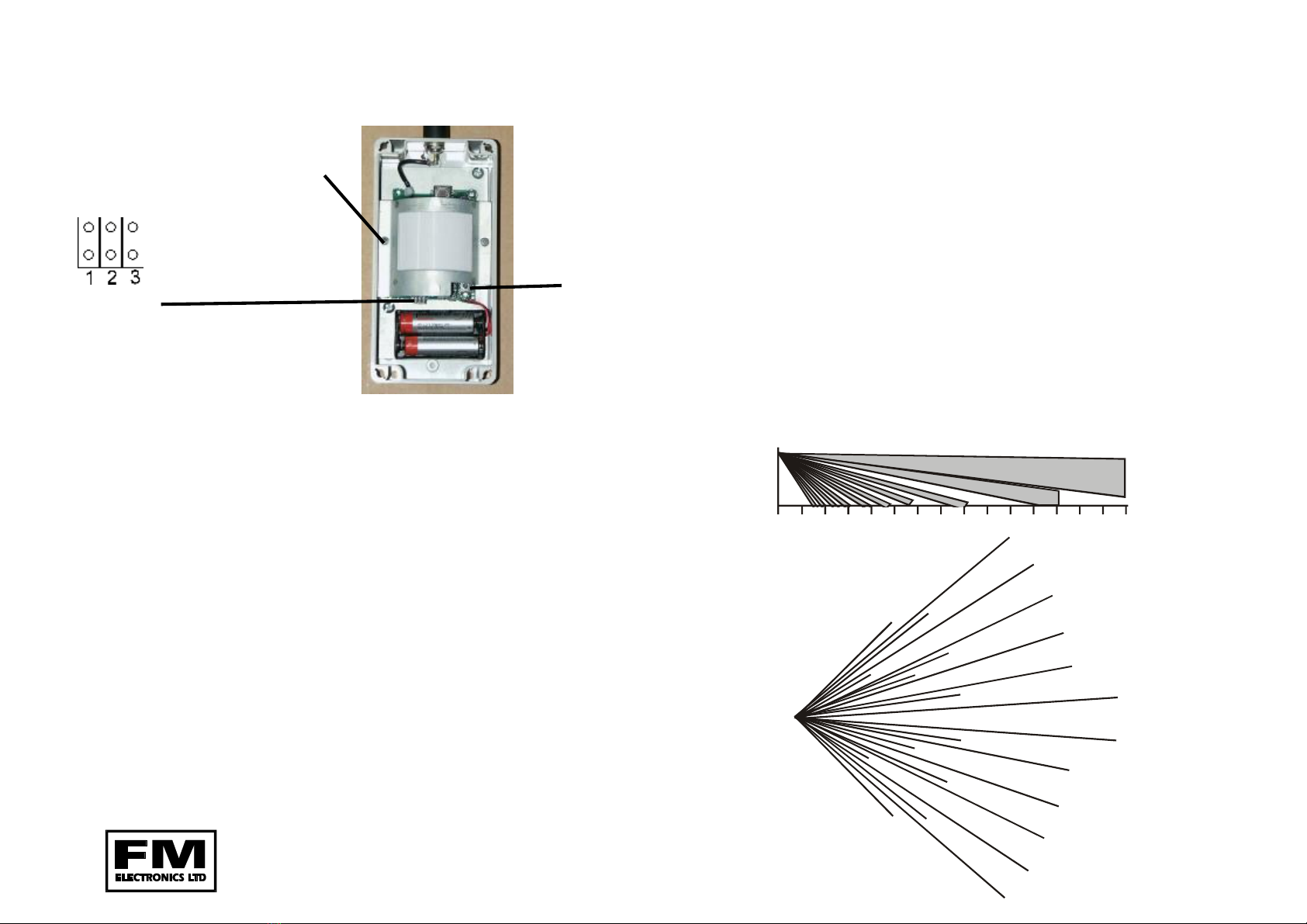
NOLINKS FITTED - Pulsecount =2
LINK 3FITTED - Nopulsecount
LINK 2FITTED - Pulsecount =4
LINK 1FITTED - Overrides the2minuteinhibit. WiththislinkfittedthePIR will
transmitagain after 2minuteswithcontinuousmovement
present. Link1sunaffectedbylinkstwoor three
ADDINGADETECTOR TOTHE 4000 SERIES CONTROLPANEL
1.Connect thebatteries. The detector will takeapprox. 5minutestosettle. Soalthough
you can programit, the PIR will not detect movement forthe initial5minutes& until 2
or moreminutesof nomovementhavebeen detectedinnormaloperation.
2.Enter theengineersprogrambykeyingin the engineerscode (default=4679). (The
alarmLED will flashslowlytoindicatethat you areinengineer mode).
3.Keyin thenumberof thezone towhichthe detectoris tobeallocated. i.e.
FM4000E, 01 for zone 1.08for zone8.
FM4000X, 011 for zone1device1.012for zone1 device2.
4.Press the walktest button. The control panel will bleeptwice and azone LED will
illuminate. The zoneLED’sindicatethenumberof devicesprogrammedontothezone.
5.Press the FullSetkeytoaccept,checkthesignalstrength(see the control panel
instructionsfordetails) & then mount thedeviceincorrect position.
6.Exit Engineering mode bypressing 48onthe control panel.
Lensadjust
screws
ForestValeRoad,Cinderford, Gloucestershire, GL14 2PH
Tel: ( 01594) 827070 Fax: ( 01594 ) 827066
Programlinks
Normal PCB central
CI-220 ISSUE1
PDFcreated withpdfFactorytrialversion www.pdffactory.com


