manuals.online logo
Brands
  1. Home
  2. •
  3. Brands
  4. •
  5. Bosch
  6. •
  7. Security Sensor
  8. •
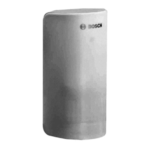
  9. Bosch ISW-EN1262 User manual

Bosch ISW-EN1262 User manual

Other Bosch Security Sensor manuals

Bosch DS1103i User manual

Bosch

Bosch DS1103i User manual

Bosch D-tect 150 SV Professional User manual

Bosch

Bosch D-tect 150 SV Professional User manual

Bosch ISN-AP1-T User manual

Bosch

Bosch ISN-AP1-T User manual

Bosch ISN-SM-50 User manual

Bosch

Bosch ISN-SM-50 User manual

Bosch DS9370E User manual

Bosch

Bosch DS9370E User manual

Bosch DS835 User manual

Bosch

Bosch DS835 User manual

Bosch ISC-CDL1-W15G User manual

Bosch

Bosch ISC-CDL1-W15G User manual

Bosch DS9360 User manual

Bosch

Bosch DS9360 User manual

Bosch RFPR-ZB User manual

Bosch

Bosch RFPR-ZB User manual

Bosch DS1109i Operating instructions

Bosch

Bosch DS1109i Operating instructions

Bosch BMA400 Instruction Manual

Bosch

Bosch BMA400 Instruction Manual

Bosch MX934i User manual

Bosch

Bosch MX934i User manual

Bosch IR LD 1.0 User manual

Bosch

Bosch IR LD 1.0 User manual

Bosch LTC 2210 Series User manual

Bosch

Bosch LTC 2210 Series User manual

Bosch ISC-PDL1-W18G User manual

Bosch

Bosch ISC-PDL1-W18G User manual

Bosch ISC-PDL1-W18H User manual

Bosch

Bosch ISC-PDL1-W18H User manual

Bosch Blue Line Q1 User manual

Bosch

Bosch Blue Line Q1 User manual

Bosch DS938Z User manual

Bosch

Bosch DS938Z User manual

Bosch FCH-T320 Owner's manual

Bosch

Bosch FCH-T320 Owner's manual

Bosch Truvo User manual

Bosch

Bosch Truvo User manual

Bosch FCP-O 500 User manual

Bosch

Bosch FCP-O 500 User manual

Bosch GMS 120 Professional User manual

Bosch

Bosch GMS 120 Professional User manual

Bosch DS150I User manual

Bosch

Bosch DS150I User manual

Bosch ISP-PPR1-WA16x User manual

Bosch

Bosch ISP-PPR1-WA16x User manual

Popular Security Sensor manuals by other brands

Honeywell Home PROSiXCOCN Installation and setup guide

Honeywell Home

Honeywell Home PROSiXCOCN Installation and setup guide

Duevi SIRPZ-RB-868 Operation

Duevi

Duevi SIRPZ-RB-868 Operation

RKI 65-2483RK Operator's manual

RKI

RKI 65-2483RK Operator's manual

Nortech PD160 Enhanced Series user manual

Nortech

Nortech PD160 Enhanced Series user manual

Omron K8AC-H2 manual

Omron

Omron K8AC-H2 manual

Agilent Technologies G8610 Series Quick reference card

Agilent Technologies

Agilent Technologies G8610 Series Quick reference card

Shinko SE2EA-1-0-0 instruction manual

Shinko

Shinko SE2EA-1-0-0 instruction manual

Det-Tronics X Series instructions

Det-Tronics

Det-Tronics X Series instructions

ACR Electronics COBHAM RCL-300A Product support manual

ACR Electronics

ACR Electronics COBHAM RCL-300A Product support manual

TOOLCRAFT 1712612 operating instructions

TOOLCRAFT

TOOLCRAFT 1712612 operating instructions

Elkron IM600 Installation, programming and functions manual

Elkron

Elkron IM600 Installation, programming and functions manual

THORLABS PDA10JT user guide

THORLABS

THORLABS PDA10JT user guide

Waeco UV-DETECT operating manual

Waeco

Waeco UV-DETECT operating manual

Intermatic IOS-DSIMF manual

Intermatic

Intermatic IOS-DSIMF manual

Siemens AZL66 Series manual

Siemens

Siemens AZL66 Series manual

BTI Profiline Multi Finder operating instructions

BTI

BTI Profiline Multi Finder operating instructions

Challenger SL01 instruction manual

Challenger

Challenger SL01 instruction manual

DMP Electronics 1122INT installation guide

DMP Electronics

DMP Electronics 1122INT installation guide

manuals.online logo
manuals.online logoBrands
  • About & Mission
  • Contact us
  • Privacy Policy
  • Terms and Conditions

Copyright 2025 Manuals.Online. All Rights Reserved.

ISW-EN1262 Installation Guide PIR Motion Sensor-Transmitter
Overview
The ISW-EN1262 is a low-current motion detector that is highly
sensitive to moving heat (infrared radiation) sources.
Use the ISW-EN1262 in residential and low-traffic commercial
applications.
1.0 Open the Detector Housing
1. Insert a small flat-blade screwdriver at a 45°angle into the tab
on the bottom of the unit.
2. Press downward on the handle of the screwdriver until the
latch holding the cover to the housing base releases.
Refer to Figure 1.
Figure 1: Open the Housing
Figure 2: Detector Components
1
2
3
4
6
7
5
NZ
1 - Wall Tamper pins
2 - Battery
3 - Circuit Board Attachment latch
4 - Housing Tamper switch
5 - Look-down lens
6 - Reset button
7 - Frequency Band pins
2.0 Mount the Housing Back Plate
1. Pull the circuit board attachment latch and lift the circuit board
out of the housing.
Refer to Figure 2.
2. Use a 3/16 in. (4.8mm) bit to drill out the tamper rivet hole
index. Refer to Figure 3 on page 1.
3. Install the tamper wall anchor.
Figure 3: Mounting Holes
1
2
3
2
2
3
2
1 - Taper rivet hole
2 - Corner- mount hole
3 - Wall mount hole
4. Mount the housing using either the three wall-mount holes or
the four corner-mount holes.
- Use a 4 mm (5/32 in.) bit to drill the appropriate housing
holes.
- Use the included screws to mount the housing.
If using the wall tamper:
-Ensure that the wall tamper rivet depresses the
wall tamper switch. Refer to Figure 4.
-Remove the jumper plug from the wall tamper
selection pins. Refer to Figure 2, page 1.
Figure 4: Wall Tamper Switch
12
1 - Wall tamper rivet
2 - Wall tamper switch arm
© Bosch Security Systems, Inc., 2010
130 Perinton Parkway, Fairport, NY 14450 USA
www.boschsecurity.com
F01U126800-03
Installation Guide
05530A
4/1
0
ISW-EN126
2
Page 2 of
2
3.0 Select the Frequency Band
Select the appropriate frequency band for your geographic area.
1. Place a selection jumper on the appropriate Frequency Band
pins (refer to Figure 5).
2. Press the Reset button.
Figure 5: Frequency Band Settings
123
NZ
NZ
NZ
NZ
1 - North America (902 MHz to 928 MHz) (default)
2 - Australia (915 MHz to 928 MHz)
3 - New Zealand (921 MHz to 928 MHz)
When pressing the Reset button, do not touch the
Frequency Band pins. Touching the Frequency Band
pins while pressing the Reset button can inadvertently
set the detector to the wrong frequency band.
4.0 Mask the Zones
If masking is required, use Figure 6 to mask the appropriate zones.
Use opaque masking material, such as electrical tape.
Figure 6: Mask Zones
1
2
0 m
8 m
2 m
8 m
6 m
4 m
6 m
4 m
6 m
2 m
4 m
0 ft
13 ft
13 ft
8 m 10 m 12 m
13 ft 26 ft 39 ft
2 m
0 m
14 m
26 ft
26 ft
40 ft
12.2 m
20 ft
20 ft
6.1 m
6.1 m
1
2
3
4
5
6
7
8
9
10
11
1 - PIR zone diagram
2 - Lens view diagram
To enable the look-down zones, peel the mask from the look-down
lens. Refer to Figure 2 on page 1 for the location of the look-down
lens.
5.0 Install the Battery
Remove the tab from the battery’s (+) terminal.
Refer to Figure 2, page 1.
The detector must stabilize for at least 3 min after
power-up, at which time the detector is not
operational. During this period, the LED blinks once
per second.
When the 3-min stabilization period ends, the
detector requires a 2-sec quiet period. After the 2-sec
quiet period, the detector enters walk-test mode and
remains in this mode until it detects no motion for
120 sec.
6.0 Register the Transmitter
To ensure that the detector is supervised by the system receiver,
you must register its transmitter with the system receiver. Each
detector has a unique factory-programmed identification number.
Refer to the receiver, network coordinator or control panel
installation instructions for details on registering a transmitter.
1. If necessary, open the detector housing.
2. When prompted to reset the detector, press the Reset button.
Refer to Figure 1 on page 1.
If using the optional housing screws for added security, use a
2.78 mm (7/64 in.) bit to drill out the housing holes on the top
and bottom of the detector housing.
3. Close the detector housing.
7.0 Test the Detector
To ensure correct operation, test the detector after it
registers with the system receiver. To test the
detector, activate each of the conditions and ensure
that an appropriate response occurs.
1. During the 3-min stabilization period, press and release the
housing tamper switch to cause a tamper condition.
Refer to Figure 2, page 1, for the location of the housing
tamper switch.
2. When the stabilization period is complete, replace the housing
cover, and walk in front of the detector to create an alarm.
8.0 Specifications
Dimensions
(H x W x D):
11.4 cm x 6.4 cm x 4.1 cm
(4.5 in. x 2.5 in. x 1.6 in.)
Operating
Temperature:
0°C to +60° C (+32°F to +140° F)
Humidity: 0 - 90% (non-condensing)
Battery: 3 V lithium (CR123A or DL123A)
Typical Battery Life: 2 years
Tamper: Housing and/or wall tamper (optional)
PIR RF interference
Immunity:
Greater than 30 V/m 26 MHz - 1 GHz
Alarm Lockout Time: 3 min
Mounting Height: 2.1 to 2.7 m (7 to 9 ft)
Standard Lens
Coverage:
12.2 m x 12.2 m (40 ft x 40 ft)
Compatible Receivers: ISW-EN4204R, ISW-EN4216R, and
ISW-EN7280