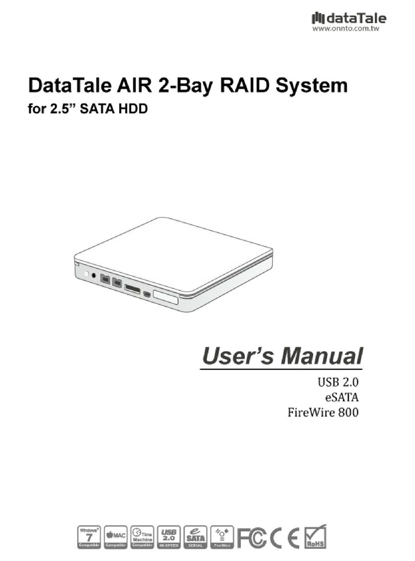
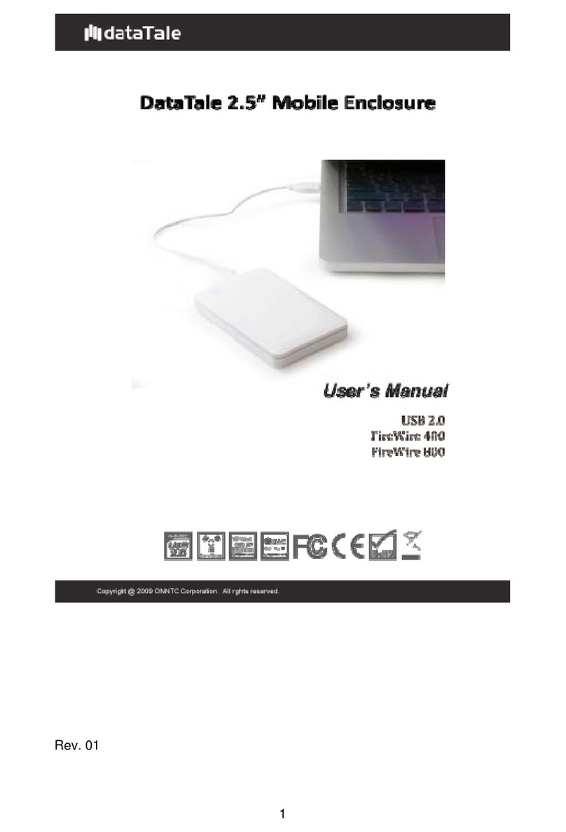
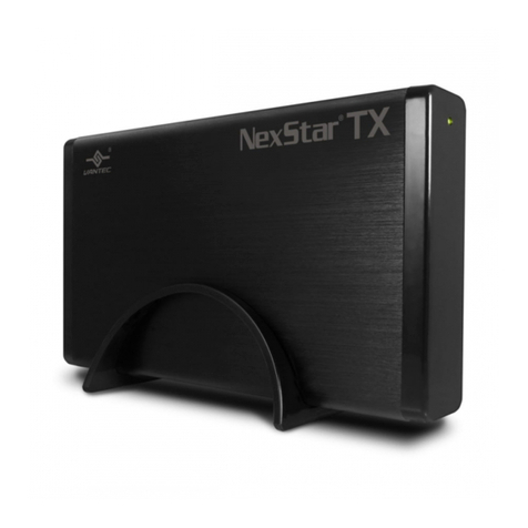
DataTale 3.5" Portable HDD Enclosure User manual

1
Rev.02

2
TableofContents
GENERALINFORMATION ............................................................................................................... 3
COPYRIGHT.................................................................................................................................................... 3
NOTICESANDCLASSIFICATIONS ......................................................................................................... 3
CONTACTUS.................................................................................................................................................. 3
PRECAUTIONSFORTHEENCLOSURE ........................................................................................ 4
INTRODUCTION................................................................................................................................. 5
FEATURES.......................................................................................................................................................... 5
SYSTEMREQUIREMENT ................................................................................................................. 6
PC ........................................................................................................................................................................... 6
MAC ....................................................................................................................................................................... 6
OPTIONALACCESSORIES ................................................................................................................................. 6
PACKAGECONTENTS....................................................................................................................... 7
SYSTEMUNITVIEWS ....................................................................................................................... 8
FRONTVIEW ..................................................................................................................................................... 8
REARVIEW........................................................................................................................................................ 8
ASSEMBLINGTHE3.5”SATAHDDENCLOSURE ..................................................................... 9
PUTTINGON&SWITCHINGPOWERPLUGONAC/DCADAPTER...................................13
CONNECTINGTHEENCLOSURETOACOMPUTER ...............................................................15
CONNECTINGMULTIPLEDEVICES ............................................................................................16
PORTABILITYWITHEASE&CONVENIENCE .........................................................................17
SAFEREMOVALOFTHEENCLOSURE.......................................................................................18
EXTERNALBOOTUP.......................................................................................................................18
PC .........................................................................................................................................................................18
MAC .....................................................................................................................................................................18
ESATAPCIEXPRESSCARDINSTALLATION............................................................................19
SYSTEMREQUIREMENTS.............................................................................................................................. 19
HARDWAREINSTALLATION......................................................................................................................... 19
DRIVERINSTALLATION ................................................................................................................................ 20
VERIFYDRIVERINSTALLATION .................................................................................................................. 20
MacOS:..............................................................................................................................................................20
WindowsOS: ...................................................................................................................................................20
Windows2003andXP: ..............................................................................................................................21
Windows2000: ..............................................................................................................................................21
Q&AS ...................................................................................................................................................22
HDDCAPACITY ............................................................................................................................................. 22
DISCREPANCYINREPORTED&ACTUALSIZECAPACITY........................................................................ 22
APPENDIX:SPECIFICATIONS ......................................................................................................23

3
GENERAL INFORMATION
COPYRIGHT
Copyright @ 2009 ONNTO Corporation. All rights reserved. No part of this
publication may be reproduced, stored in a retrieval system, or transmitted in
any form or by any means, electronic, mechanical, photocopying, recording or
otherwise, without the prior written consent of ONNTO Corporation.
The product information provided in this manual is subject to change
without prior notice and does not represent a commitment on behalf of the
vendor. The vendor assumes no liability or responsibility for any errors that
may appear in this manual.
NOTICES AND CLASSIFICATIONS
FCC-B Radio Frequency Interference Statement
This device complies with Part 15 of the FCC rules. Operation is subject to
the following two conditions:
This device may not cause harmful interference.
This device must accept any interference received, including interference that
may cause undesired operation.
This equipment has been tested and found to comply with the limits for
a Class B digital device, pursuant to Part 15 of the FCC rules. These limits
are designed to provide reasonable protection against harmful interference
when the equipment is operated in a commercial environment. This
equipment generates uses and can radiate radio frequency energy and, if not
installed and used in accordance with the instruction manual, may cause
harmful interference to radio communications.
CONTACT US
We are committed to offer economical, high-quality connectivity and storage
enclosure solutions to the market. Your questions, inquiries or comments are
welcomed. For Technical Support, please go to our website at
www.onnto.com.tw
ONNTO Corporation
3F, No. 60, Lane 321, Yang Guang St.,
Nei Hu, Taipei 114 Taiwan
Tel: +886-2-8797-8868
Fax: +886-2-8797-4801
Email: [email protected]om.tw

4
PRECAUTIONS FOR THE ENCLOSURE
♦The main circuit board of the Enclosure is susceptible to static
electricity. Proper grounding is required to prevent electrical damage
to the Enclosure or other connected devices, including the host
computer. Always place the Enclosure on a smooth surface and avoid
all dramatic movement, vibration and percussion.
♦Do NOT allow water to enter the Enclosure.
♦Installation of additional equipment in the host computer may be
required. Visit our website to download the latest product information
updates.
♦Do NOT attempt to service this device yourself. Disassembling the
Enclosure’s inner parts will expose you to dangerous voltages or other
hazards.
♦Do NOT block the ventilation. Proper airflow is required to ensure
reliable operation and to prevent overheating.
♦Do unplug the Enclosure from the electrical outlet when not in use to
provide an ecological friendly environment.
♦Use only the AC/DC Adapter provided with the Enclosure.

5
INTRODUCTION
Thank you for purchasing the DataTale Portable 3.5-inch HDD Enclosure.
The DataTale Portable 3.5-inch HDD Enclosure provides easy access and
convenient travel for your hard drive with all four universal interfaces available.
The installation instructions in this manual apply to the following models:
TQ-M12H (SATA-eSATA/USB 2.0/FireWire 400/FireWire 800 combo)
TD-M11H (SATA-eSATA/USB 2.0 combo)
Please thoroughly read and follow the instructions provided in this
manual. Failure to do so may result in damage to the Enclosure, and any or
all of the connected devices.
Features
Supports current SATA II compliant HDDs, fully backward compatible
with SATA 1.0 and SATA 1.0a compliant HDDs
Supports Hi-Speed USB (USB2.0 connection), IEEE 1394a (FireWire
400 connection), IEEE 1394b (FireWire 800 connection), or eSATA
(SATA-eSATA connection)
Combines Enclosure and 1394 repeater functionality (TQ-M12H only)
Connects to host by plug-n-play, not requiring any IT expertise or
software installation
Reduces power consumption with HDD spin down support
Prevents damages from over-tightened HDDs with auto-limiting
segmented screws
Dissipates heat efficiently with aluminum housing and open-back
mechanism
Prevents sliding with TPU (Thermoplastic Polyurethane) edges
Simplifies HDD installation by using the SmartGuider* mechanism and
enables effortless HDD access with portability
Features Twist Locks for hard drive portable security
SmartGuider is a tray-less device that utilizes the simplicity of a handle
and screws. The integrated handle is attached to the HDD with auto-limiting
segmented screws. Then, the entire setup can be slide into the unit by
aligning the screws with the specially designed guides. This enables flexibility
in removal and insertion of the HDD with ease.
Any loss, corruption, or destruction of data is the sole responsibility of
the user. Under no circumstances will the manufacturer be held liable for the
recovery or restoration of any data.

6
System Requirement
To use the DataTale Portable 3.5-inch HDD Enclosure, the minimum system
configuration in the host computer require the following:
PC 266MHz or faster CPU (Windows Vista requires a minimum 800MHz
CPU)
64MB of RAM (Windows Vista requires 512MB of RAM)
Microsoft Windows 2000, XP, 2003, or Vista
One available eSATA port, USB 2.0, IEEE 1394a, or IEEE 1394b port
MAC
Macintosh PowerPC or Intel Core Duo processor
64MB of RAM (Mac OS X 10.4 requires 256MB of RAM)
Mac OS X 10.2 or higher (PowerPC) or Mac OS X 10.4 (Intel) or higher
One available eSATA port, USB 2.0, IEEE 1394a, or IEEE 1394b port
3.5-inch SATA compatible hard drive is required for the Enclosure. Once
the HDD is formatted, the actual available storage capacity can vary
depending on the selected operating environment (normally 5-10 % less).
Optional Accessories
eSATA PCI, PCI-X, or PCI-Express Card

7
Package Contents
To get started, please review the package contents for each model.
TQ-M12H
Enclosure Unit with Handle
USB Type A to mini-B Cable
IEEE 1394a Cable
IEEE 1394b Cable
eSATACable
AC/DC Adapter
4 HDD Screws
Thermal-shield Pad
Quick Start Guide
TD-M11H
Enclosure Unit with Handle
USB Type A to mini-B Cable
eSATA Cable
AC/DC Adapter
4 HDD Screws Thermal-shield Pad
Quick Start Guide
Please keep all package contents and packaging material in the event
that the product must be returned.

8
SYSTEM UNIT VIEWS
Front View
Power Button
FireWire 800 (2 ports)
FireWire 400
USB Mini-B Port
eSATA Port
DC IN
Lock Slot
TQ-M12H SATA-eSATA/USB 2.0/FireWire 400/FireWire 800
USB Type-B PorteSATA Port
Power Button
DC IN
Lock Slot
TD-M11H SATA-eSATA/USB 2.0
The Power Button will indicate the current operating status.
Rear View
Twist Lock ( in Lock position) Twist Lock
Handle

9
ASSEMBLING THE 3.5” SATA HDD ENCLOSURE
To begin using the 3.5” SATA HDD Enclosure, simply install a 3.5” SATA hard
drive into the Enclosure by completing the following assembly steps:
CAUTION
(Fasten the Handle on the Hard Drive)
1. Place the hard drive with the metal cover side facing up and ensure that
the interface connectors are oriented toward your left side.
Connectors
2. Position the handle to the hard drive end, the end without interface
connectors, and align it with the screw hole openings.
Connectors

10
3. Locate the auto-limiting segmented screws included inside the package.
Insert the first screw and fasten the handle onto the hard drive. Tighten the
first screw securely to ensure that proper alignment is maintained. Repeat
the same for the remaining 3 screws.
4. After the auto-limiting segmented screws are tightened, test slides the
handle to make sure that the handle glide smoothly.
The SmartGuider Package includes one hard drive handle and four
auto-limiting segmented screws. The auto-limiting segmented screws are
designed to prevent the hard drive and/or the handle from damages due to
over-tightening. Furthermore, the SmartGuider design makes the handle
slide easily without any tightness.

11
(Inserting the Hard Drive into the Enclosure)
5. Place the Enclosure with its open-back (side with the Twist Locks) facing
you. Make sure the Twist Locks are in the “unlock” position (lined up with
the edges of the casing).
Unlock
Lock
6. Hold the hard drive. Align the SmartGuider (with the hard drive) into the
guide rails.
The Thermal-Shield Pad must be placed on the hard drive before
installation. When the hard drive is inserted on its reverse side, it won’t be
able to align and the hard drive cannot be inserted.

12
7. Slide the hard drive into the Enclosure and firmly push forward until a
“thump” sound is heard. Ensure that the connectors of the hard drive are
properly attached to its receptacle inside the housing.
8. For typical-sized hard drive, turn the Twist Locks inward 90 degrees (see
option A). For smaller footprint hard drive, turn the Twist Locks inward
around 140 degrees (see option B). Make sure the Twist Locks are in the
“lock” position and securely hold the hard drive in place. Now, the
Enclosure is ready for connection to a computer!
A
B

13
PUTTING ON & SWITCHING POWER PLUG ON
AC/DC ADAPTER
1. Find the AC/DC Adapter in the package. The package may include
different types of plug heads vary by region.
2. Press the click release and slide the existing Power Plug from the AC/DC
Adapter.

14
3. Slide the selected Power Plug onto the AC/DC adapter. Now, it is ready to
be used!

15
CONNECTING THE ENCLOSURE TO A
COMPUTER
Complete the following steps to connect the Enclosure to a host computer.
The Enclosure should only be connected to a computer via one interface
at a time. Connection of the Enclosure to a computer via two or more
interfaces simultaneously is not recommended.
1. Connect the AC/DC adapter to the Enclosure. Then, press ON the Power
Button to ensure that the LED Indicator (Color BLUE) is active.
2. Insert the USB 2.0, eSATA, or FireWire 400/800 connector into the
corresponding port of the Enclosure, and connect the cable to the host
computer.
Due to compatibility issues, if you use the eSATA interface to do the data
transfer, the Silicon Image eSATA host controller is highly recommended.

16
3. The External Hard Drive (the Enclosure with hard drive installed) should be
detected by the host computer. When the hard drive is being accessed,
the Power Button (LED Indicator) will flash in blue.
Connecting Multiple Devices
Using FireWire 400 or 800 to connect to the host, you can connect other
computer hardware or digital devices to your Enclosure. This connection is
called “Daisy Chain”. Items connected to the Enclosure may be such as
digital video camera, another HDD, DVD writer, and much more. Since TQ-
M12H has two FireWire 800 ports, it is highly recommended to use FireWire
800 to connect to the host, and Daisy Chain with another FireWire 800
connector to maximum speed transfer.

17
PORTABILITY WITH EASE & CONVENIENCE
1. Secure the hard drive position well with the Twist Locks to prevent the hard
drive from falling out during travel or movement.
2. Now, the External Hard Drive is ready to be carried around anywhere with
ease and comfort!

18
SAFE REMOVAL OF THE ENCLOSURE
Safe removal of the Enclosure from the host controller is highly recommended,
especially when switching interfaces. In order to safely remove your
Enclosure from the host controller, you would need to eject the device on your
host controller system.
If using a Mac System, safe removal of the Enclosure from the host for
all interfaces is necessary.
If using a PC System, depending on the eSATA controller, the host may
handle external eSATA HDD devices as internal HDD devices. If so, safe
removal of the Enclosure from the host is unnecessary.
EXTERNAL BOOTUP
External Bootup may be required if the user has two different operating
systems set up in both the host computer and the Enclosure.
PC
The External Bootup with different interface:
OS \ Interfaces USB 2.0 FireWire eSATA
Windows No No Yes
DOS Yes No Yes
Linux No No Yes
MAC
The External Bootup varies with different platform and interfaces:
eSATA
Platform \ Interfaces USB 2.0 FireWire Mac driver
Built-in No driver
Built-in
Power PC CPU
(G4 or Later) No No Yes No
CoreDuo Yes No Yes No
Intel-
based
CPU Core2Duo
Or Later Yes Yes Yes No
If the computer does not come with eSATA interface and an optional
eSATA card is added, choosing the card that comes with the built-in driver in
the operation system is highly recommended.

19
eSATA PCI EXPRESS CARD INSTALLATION
Complete the steps provided in this section to install the eSATA PCI Express
Card to use with the Enclosure. The eSATA PCI Express Card provides a
host computer with two Windows and Mac compatible eSATA ports.
System Requirements
Windows 2000 with Service Pack 4 or later
Windows XP with Service Pack 2 or later
Windows 2003 with Service Pack 1 or later
Mac OS 10.4.x or later
An available PCI-Express slot
CD-ROM or DVD-ROM drive
Hardware Installation
1. Power “off” and unplug your computer.
2. Remove the housing of your computer and locate an available PCI-Express
slot on your motherboard.
3. Insert the card in the available PCI-Express slot. Ensure that the card is
firmly seated in the slot.
4. Replace the housing of your computer.
System
Frame
Screw
PCI-Express
Card
Mounting
Bracket

20
Driver Installation
Follow the provided prompts to complete the driver installation.
For the Windows system, the “Add New Hardware Wizard” will open
automatically. Insert the installation CD included in the package, navigate to
and open the installation file.
For Mac OS, insert the installation CD and locate the Mac driver installation
file. Follow the provided instructions to complete the driver installation.
Please refer to User’s Manual under eSATA Host Card on our website.
Verify Driver Installation
Mac OS:
If a driver installation failure error message appears after restarting the
computer, follow the recommendations provided in the error message.
Windows OS:
1. Right-click the My Computer icon on your desktop and choose Manage
from the pop-up menu.
2. Double-click Device Manager.
3. Double-click SCSI and RAID controllers.
4. Verify that the SiI 3132 SATALink Controller appears, as shown below.
This manual suits for next models
2
Table of contents
Other DataTale Enclosure manuals
Popular Enclosure manuals by other brands
Dell
Dell Storage Center SC200 Service guide
Electro-Voice
Electro-Voice Coronet Assembly instructions
Ericsson
Ericsson BDV BS 101 01 installation instructions
StarTech.com
StarTech.com INFOSAFE SAT3540ER instruction manual
Akitio
Akitio Thunder3 Quad Setup guide
SilverStone
SilverStone MS06 Lnstallation guide
