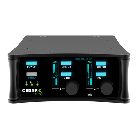
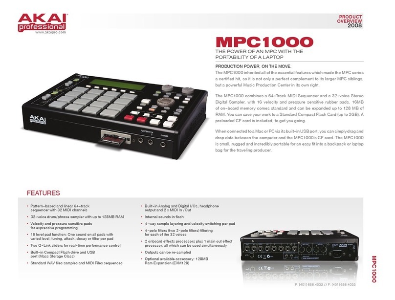
Dateq SPL5 User manual

SPL-5 MKII
SPL-5 MK2_204901_V1.0EN
audio limiter
&
sound level logger
Manual
Machine Translated by Google

Due to the nature and functionality of this product, it should only be used and installed by
professional and certified installers. It is not intended for use or resale by consumers. The
manufacturer does not support consumer use.
SPL-5 MK2_204901_V1.0EN
Machine Translated by Google

NL DATEQ SPL5 MK2 Manual Safety instructions 3
Safety instructions
14.The mains power cable or mains power cord should be used if the appliance is not used for a long period of time
5. The device should never be used in the immediate vicinity of water; prevent the
recommended cables, as described in the user manual and/or stated on the connection side of the
device.
used, unplugged from the mains supply.
15. In all cases when after an incident there is a risk of unsafe operation of the
possibility of ingress of water and moisture.
10.The device may only be connected to a legally approved (edge) earthed
device, such as:
• after the mains cable or mains power cord has been damaged • after foreign objects
or liquids (including water) have entered the device • after the device has been dropped or the housing
has
been damaged after noticing a change in the operation of the device, it must be checked by authorized
technical personnel.
16. The user must not carry out any work on the device other than that described in the user manual.
mains connection.
6. The appliance should only be placed or mounted in the locations recommended by the manufacturer
manner.
11.The mains cable or the mains voltage cable must be laid in such a way that it cannot reasonably be
walked on or that no objects can be placed on or against it that could damage the cable. Special
consideration should be given to the point where the cable is attached to the appliance and where
the cable is attached to the mains connection.
12.Prevent foreign objects and liquids from entering the device.
7. The appliance must be placed or mounted in such a way that nothing hinders proper ventilation
2. All warnings marked on the device must be followed.
1. All safety instructions, warnings and instructions for use must be read first
become.
3. The instructions for use must be followed.
stands.
heating installations, stoves and other heat-producing equipment (including amplifiers) are placed.
8. The device should never be placed in the immediate vicinity of heat sources such as parts of
9. Only connect the device to the correct mains voltage using the manufacturer's power supply
4. Keep the instruction manual for future reference.
13.The appliance should be cleaned as recommended by the manufacturer.
Machine Translated by Google

Index
Safety instructions..........................................3 Installation..... .................................................... ...17
Introduction.......................................... .............5
Configuration.................................. ..............17
License configuration.................................. ...............18Installation........................................ .....................6
Connections.......................... .....................7 Unlocking the limiter ..................... ........18 Audio
outputs.................................................. .9 Live.................................................. ...............19
External attenuator................................... ...9
Limiter configuration......................................20
Signals.... .....................................10 Fashion.......... .............................................20
Use... .................................................... .......11
Limiter settings.....................................20 Technical
specifications... ...............................13 Certification date.................. ....................20
General............................... ........................13 Microphone settings........................ ......20
Inputs.......................................... ............13 Time slots..................................... .................21
Outputs.................................. ....................13 Bypass calendar............................... ...............21
General.................................. ....................13 Display................................. ............................22
Sound........................ ....................................13
Firmware update............ ............................23
Limiter.................. .............................13 Settings........................ ............................23
Memory.................. ............................13 Network settings.................. ....................23 External
signalling............................... ......13 Device.......................................... ............23 Power
supply.................................. ...............13 History.................................. ............................24
Dimensions and weight.................. ...............13Product support..................................................
28 Setup Introduction.....................................16
Machine Translated by Google

EN DATEQ SPL-5 MK2 Manual Introduction 5
Introduction
The SPL5 MK2 is a sound pressure limiter that stores sound pressure data for a minimum period
of 180 days. Other data, such as switching on, exceeding the maximum level and any (attempted)
sabotage are also registered.
This keeps managing and checking the equipment quick and clear!
With the special SRL-1 circuit breaker you can connect an external warning lamp and disconnect
the power supply, for example the DJ booth monitor. This way, sound can always be played at
the maximum permitted sound level, without affecting the sound quality.
Normally, users can only view settings and logs. To adjust the settings, an additional
password and a license file are required. To connect to the SPL-5 MK2 you need a
Windows computer with USB support. If the SPL-5 MK2 is connected to a local network or the
internet, it is possible to read the limiter remotely.
The special calendar functions allow you to allow different sound levels over the course of a day
and a year.
At the time of release, the device supports Windows 7 and newer.
In this way, the level always remains within the permissible limits.
The configuration software allows the SPL-5 MK2 to be read and adjusted.
The limiter uses a measuring microphone to determine the current sound pressure in the room.
When this level threatens to become too loud, the limiter will regulate the level slightly.
Machine Translated by Google

Figure 1: Installation of the SPL-5 MK2
6 Installation DATEQ SPL-5 MK2 manual EN
Connections
Installation
To prevent the connections from being changed after the limiter has been adjusted and sealed, the
limiter's connections are no longer accessible after sealing. To access the limiter connections,
remove the right (sealable) cover.
Before adjustment, the power amplifiers are set to maximum power. The limiter will attenuate the
signal as necessary. As soon as the limiter has been adjusted, the pre-set limit can in principle
no longer be exceeded. Should this happen, the signal will automatically be slightly weakened, so
that the total sound pressure remains within the preset standard.
The SPL5 MK2 is equipped with balanced inputs and outputs. This type of connection guarantees
good sound quality, even over longer distances. Once the device has been adjusted, a cover is
placed over the connections, so that making adjustments afterwards is no longer possible. When
the cover is removed, the SPL5 MK2 will register this. The limiter can then only be reactivated using
the key.
microphone input; XLR 3-pin female
Now loosen bolt (A) with a Torx screwdriver (see drawing). Now remove the 4 torx screws
(B) from the top cover. Now the lid can be removed. First lift the front slightly, then slide the cover
back. The connection plate of the limiter is now visible.
The limiter is installed between the sound source (for example, the mixing desk, the
preamplifier, etc.) and the amplifier. See figure 1.
Machine Translated by Google

Pen Function
Pen Function
Pen Function Description
Installation 7
Description
Description
Pen Function
EN DATEQ SPL-5 MK2 manual
Pen Function
Description
Description
3 Audio -
Dates
Not used
3 Dates +
Table 3: audio output connections
1 Mass
Audio Earth
Audio Earth
Audio in phase
3 RX-D+
Dates
Soil
1 Mass
5
Table 5: Network connections
8
Audio in phase
Power and audio
Audio out of phase
1 VCC +
Dates
2Audio +
2Audio +
Table 1: Microphone input connections
1 TX-D+
4
4 GND
2Audio +
Dates
Not used
Table 4: USB connections
Power supply
Audio Earth
1 Mass
6 RX-D –
Not used
Dates
Power and audio
Table 2: Audio input connections
Audio out of phase
7
Not used
2 TX-D –
3 Audio -
3 Audio -
2 Dates –
Dates
Audio outputs left and right; XLR 3-pin male
signaling connector; DB-25 female
USB port; USB B female
Audio inputs left and right; XLR 3-pin female
Network port; RJ45 female
Machine Translated by Google

Pen Input/output
DATEQ SPL-5 MK2 manual EN
Function
Description
Pen Function
8 Installation
2 Reduction signalling
In
Out; 15V/ 5mA max.
9 Microphone +
In out
Out
4 Live OK signalling
13 Right audio out +
In
18...20 Analog ground (use at the audio inputs and
outputs)
11 Right audio in +
Out; 15V/ 5mA max.
Tip Data TX
Table 7: External display connections
In
5 Warning signalling
23 Right audio in -
25 Straight audio out -
Out; 15V/ 5mA max.
In
7 Safe sound pressure signalling
Data EarthSL Mass
14...17 Digital ground (use at signaling
outputs)
1 External attenuator
10 Left audio in +
Out; 15V/ 5mA max.
In
Out
Out; 15V/ 5mA max.
3 Overload signalling
12 Left audio out +
21 Microphone -
Ring Data RX
24 Left audio out -
6 Level OK signalling
In
In
Receive data
22 Left audio in -
Out
Out
8 External display
Out; 15V/ 5mA max.
Table 6: DB25 connections
Send data
Audio Inputs
Balanced inputs for the audio from the mixing console. If the mixing console only has
unbalanced outputs, pins 1 and 3 in the XLR connector must be used
External display; Jack 3 pin female
The microphone should be mounted in such a way that it can pick up both the sound from the
loudspeakers and the sound from the room. If the maximum permitted level is very low, the
microphone can be placed closer to the loudspeakers. This reduces the influence of ambient
noise.
Microphone input
Connect the supplied measuring microphone here. The connection cable of the microphone
can be extended with standard microphone cable. Pay attention to the polarity! If the
microphone is connected incorrectly, it will not work. The limiter will give an error message,
and the sound will come through strongly attenuated.
Machine Translated by Google

Installation 9
EN DATEQ SPL-5 MK2 manual
This can be useful, for example, to reduce the sound pressure behind the bar. It is also
possible to have the sound pressure decrease automatically when the terrace doors are
opened in the summer.
External attenuator
transferred. The signal from the mixing console can now be connected to pin 2, and the
ground to pin 1.
Audio outputs
Connect the power amplifiers here. If the power amplifiers do not have balanced inputs
then they can be connected between pin 2 (signal) and pin 1 (ground).
This input can be used to lower the maximum sound pressure using an external
potentiometer. By connecting a linear 10 kOhm potentiometer between pin 1 (wiper) and
pin 14, the maximum sound pressure can be temporarily reduced.
For longer cabling, it is recommended not to connect pin 1. In this case, only connect pins
2 and 3.
Machine Translated by Google

Live OK signalling
• Level OK indicates that the sound pressure is below the maximum, but approaching
the maximum allowable level (0...12dB room). • Safe
indicates that the sound pressure is more than 12dB below the maximum allowable
preset maximum.
This output indicates that the signal is being overdriven somewhere in the limiter. This
can be the audio input or the measuring microphone. This output has the same function as
the overload LED on the front of the device (Overload).
These indicators can be placed near the disc jockey or live band so they have an idea of
the sound level.
These outputs give an impression of the current sound pressure compared to the pre-set
maximum: • The
warning output becomes active as soon as the current sound pressure exceeds the
Warning signaling Level OK, Safe sound pressure
Overload signalling
An indication can be connected to this output that indicates that the limiter has
attenuated the sound pressure. This output has the same function as the reduction LED
on the front of the device (Audio reduction).
border is located.
This output is active as long as the device does not sanction. A solid-state relay can be
connected to this output, which switches off the power supply of the (live) stage. When
a live band exceeds the maximum set sound pressure, the limiter will go into sanction mode
and automatically switch off the power supply. After a predetermined time, the sanction
mode will end automatically.
External
Display This is the data connection to the optional SPL-D2 MKII, SPL-D3 or SPL-EXT3. The
external display can also be connected directly to the display port of the SPL5 MK2. A 6.3mm
Stereo Jack cable must be used for this.
Reduction signalling
DATEQ SPL-5 MK2 manual EN
10 Installation
Alerts
Machine Translated by Google

3. Timeslots:
These LEDs indicate the active timeslot. Each time slot can be assigned its own maximum
sound pressure.
9. Key Switch:
2. Display:
This shows all important data, such as the current time, the current sound pressure in various
adjustable values (dBA, dBC, Leq and peak), and the current reduction.
5 LEDs on: 80-100% reduction
overdriven (12dB above the set maximum),
8. Bypass LED:
Indicates that the limiter is in bypass. Bypass switch is pressed or bypass calendar is active.
1. Power switch:
Turns the limiter on or off.
7. USB:
USB connection for configuration and reading of the limiter.
If the limiter cover has been removed, this key will be required to reactivate the device.
Turning the key switch from red (default) to blue position resets any sanctions. After a reset,
the switch must be put back in the red position.
The reduction rate is displayed in percentage of the maximum set attenuation. By
default this is 30dB, which translates into 6dB reduction per LED. • All off:
no reduction
1 LED on: 1-20%
reduction • 2 LEDs on: 20-40%
reduction • 3 LEDs on: 40-60%
reduction • 4 LEDs on: 60-80%
reduction
4. Status LEDs:
Disable the limiter function completely. The limiter will now no longer regulate, but will continue
to register all measured values.
5. Reduction LEDs:
6.Bypass switch:
Use 11
EN DATEQ SPL-5 MK2 Manual
6 7
• SANCTION LED indicates that the limiter is in the sanction state. In the event of a fraud detection, the sanction
mode will also be activated, the LED will flash.
5
• AUDIO PRESENT indicates that the limiter has detected sound on the audio input (switches at -24dB), •
REDUCE LED indicates
that the sound level is being reduced, and the limiter therefore intervenes at this moment, • OVERLOAD LED
indicates that an input
(line input, or the microphone input).
9
3 4
28
1
•
Usage
Machine Translated by Google

14.Link:
Link connection for external display SPL-D2 MK2, SPL-D3 or SPL-EXT3.
10.Microphone:
3-pin XLR connector for a DCM-5 microphone.
12.Audio output:
Connection for XLR audio left and right from the limiter.
Sub-D 25 connector for connecting external signaling, audio in and out and microphone.
15.Ethernet:
Ethernet connection for an IP connection to the configuration software via a network.
11.Audio input:
Connection for XLR audio left and right to the limiter.
13.Signal connector:
12 Usage DATEQ SPL-5 MK2 Manual NL
13
12
10 14 15
11
Machine Translated by Google

After this, the oldest data will be automatically deleted.
SPL-5MK2_204901_V1.0EN
Outputs
Memory 180
days *sound
pressure data and events are stored for up to 180 days or when the internal memory becomes full.
THE:
External signalling
Line (left and right)................................................. ....XLR-3 male. Electronically balanced.
External attenuator.....................................0...-20dB (e.g. 10 kOhm lin potentiometer)
Signaling and switching outputs.....................15V/ 5mA max.
EN DATEQ SPL-5 MK2 Manual
Standardization
Power
supply Voltage range.....................................100... 240VAC/ 50Hz Power
consumption .................................15W
Technical specifications 13
Output Impedance.....................................50Ohm
Dimensions and weight
Front ............................................... ................483mm x 45mm (W x H) = 19inch/ 1U Cabinet
depth..................... ................................175mm
Weight............... ...........................................3.2kg
General
EU:
Audio
Frequency Response.............................................20Hz... 22kHz @ -1dB Signal-to-
Noise Ratio................................>100dB THD+N (IEC-
A) ..............................................<0.02%
General
Measuring chain built to work according to specifications of IEC-61672-1
class 2 Measuring chain
built to work according to specifications of NFS 31-122-1-2017 and decree
2017-1244 Measuring chain built to work according
to specifications of VLAREM-II cat. 1, Cat. 2 and cat.3 Measuring chain
built to work according to specifications
of DIN 61672, DIN 60651 and DIN 15905-5
included DCM-5 measurement microphone.
Limiter
Sound Threshold.....................................................50.. .120dBA (resolution 1dB)
Inputs Mic
(measurement microphone).................................................. ...XLR-3 female. Can only be used with the
France:
Line (left and right)................................................. ....XLR-3 female. Electronically balanced.
Output correction................................................-50...0dB (resolution 1dB)
Microphone correction..........................................-30...+12dB ( resolution 1dB)
Input Sensitivity.....................................+18dBu maximum Input
Impedance....... ..................................50kOhm Commom Mode
Suppression............. .........>86dB
Maximum control range setting................-6...-50dB (resolution 0.5dB)
BE:
Technical specifications
Machine Translated by Google

SPL-5 MKII
&
audio limiter
sound level logger
Configuration
Machine Translated by Google

Index
Safety Instructions................................................3 Installation. .................................................... ............17
Introduction.................................. ............................5
Configuration........................ ..................................17
Installation............... ....................................6 License
configuration................................................18 The
unlocking limiter.....................................18Connections.......... ..........................................7
Audio outputs... ..........................................9 Live...... .................................................... ...............19
External attenuator..................................... ..9
Limiter configuration................................................20
Signals ...............................................10 Fashion. .................................................... ...............20
Use.................................................. ..........................11
Limiter settings........................ ..................20
Technical specifications............................... ...............13 Certification date..................................... ....20
Microphone settings.....................................20General....... .................................................... 13
Inputs.................................................. ...............13 Timeslots.................................................. ....................21
Outputs............................. .............................13 Bypass calendar.................. .............................21
General................... .....................................13 Display.......... .................................................... .22
Audio.......................................... ............13
Firmware update.................................. ...........23
Limiter..................................... ...............13 Settings.................................. ......................23
Memory.......................... ..........................13 Network settings ..................... ....................23 External
signalling............................... ............13 Device..................................... .....................23 Power
supply.......................... .............................13 History................... ...............................................24
Dimensions and weight ................................13 Product Support.................. .............................28
Introduction to Configuration ..................... .........................16
Machine Translated by Google

This keeps managing and checking the equipment quick and clear!
With the special SRL-1 circuit breaker you can connect an external warning lamp and disconnect
the power supply, for example the DJ booth monitor. This way, sound can always be played at
the maximum permitted sound level, without affecting the sound quality.
Normally, users can only view settings and logs. To adjust the settings, an additional
password and a license file are required. To connect to the SPL-5 MK2 you need a
Windows computer with USB support. If the SPL-5 MK2 is connected to a local network or the
internet, it is possible to read the limiter remotely.
The special calendar functions allow you to allow different sound levels over the course of a day
and a year.
In this way, the level always remains within the permissible limits.
At the time of release, the device supports Windows 7 and newer.
The configuration software allows the SPL-5 MK2 to be read and adjusted.
The limiter uses a measuring microphone to determine the current sound pressure in the room.
When this level threatens to become too loud, the limiter will regulate the level slightly.
The SPL5 MK2 is a sound pressure limiter that stores sound pressure data for a minimum period
of 180 days. Other data, such as switching on, exceeding the maximum level and any (attempted)
sabotage are also registered.
16 Configuration DATEQ SPL-5 MK2 Manual UK
Configuration introduction
Machine Translated by Google

EN DATEQ SPL-5 MK2 manual Installation 17
•
The settings are normally only changed during installation. You can save all settings in a backup file
for later use or restore the original settings after changes.
•
You connect the display to a computer using a
standard USB-A to USB-B cable. After connecting the SPL-5
MK2 to your computer, the standard Windows
drivers will be loaded. You do not need additional drivers,
these are present in Windows.
•
•
Installing the standard Windows drivers the first time can take several minutes depending on your
operating system.
Apple OSX, Linux and other operating systems are not supported. Minimum screen
resolution 1400
The SPL-5 MK2 configuration software is compatible with the following operating systems:
Windows 7
Windows XP
*
Windows 8
1050 pixels.
Always use the latest software and firmware versions; these can be found at www.dateq.nl.
Windows 10
Configuration
This chapter describes the configuration and system settings of the SPL-5 MK2.
Connecting the computer
Installation
Machine Translated by Google

Unlock the limiter
18 Installation DATEQ SPL-5 MK2 manual EN
The installation license is only issued to authorized professional audio installers. If you have an SPL limiter
and need to adjust settings, please contact your local distributor or installer. You can find the nearest
supplier on the page with sales points on the Dateq website: www.dateq.nl.
Note: You must install a valid license file before starting the software.
Before you can make changes, you must enter the
license password. The password is stored in the license file
SPL5.DSR.
Each installation license is linked to a specific installation company and is not transferable to third
parties. The installation license contains all company and contact details; these are stored in the SPL
limiter during configuration.
You normally only use the configuration software to view settings and read audio logs. You do not
need a license or password to view or export data. You do need a license and a password to adjust
settings and for the first installation.
If no valid license can be found, you will be notified in the software.
The license file SPLD5.DSR must be copied to the folder containing the software.
Configuration license
Machine Translated by Google

Installation 19
EN DATEQ SPL-5 MK2 manual
Live
The status LEDs of the front panel of the limiter are also displayed so that the current status of the limiter
is immediately visible.
The live view allows you to monitor the current measurements on the SPL-5 MK2.
These measurements are displayed in green or red.
Machine Translated by Google

20 Installation DATEQ SPL-5 MK2 manual EN
!!
Limiter configuration
Configuration of sound parameters.
Input threshold: -50dB to 0dB.
The timer for sanction starts counting as soon as the overload led turns on.
Output attenuation: -60dB to 0dB.
Changes to the settings take effect immediately.
Maximum reduction: 60dB to 0dB.
Certification date
The limiter will continue to work until this date. After this date 'certification invalid' will appear in large
on the display. It also appears on every export of the log files.
The limiter will attenuate the outgoing signal by 18dB. The limiter configuration must be checked by the
installer.
Mode
• Live Limiter and recorder •
Line Limiter and recorder
In Line mode the limiter will only register the microphone signal and not include it in the control of
the outgoing signal. In this mode the limiter operates on the line signal (input threshold)
In Live mode, the limiter will include the measured microphone signal in the control of the outgoing
signal.
Microphone settings
Microphone correction: -30dB to +12dB.
Limiter settings
Maximum dBA: 50dB to 125dB.
Microphone sensitivity: 3.7mV/Pa (typical)
Sanction Settings
Time to Sanction: 10 to 360 seconds.
Maximum dBC: 50dB to 125dB.
Penalty time: 10 to 360 seconds.
Machine Translated by Google
Other manuals for SPL5
2
Table of contents
