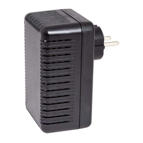
pro bel 4405 Owner's manual

ontents
1Introduction2
2Installation4
.1Signal I/O5
3onfiguration8
3.1Setting the input mode8
3. Selecting reference options9
3.3Error handling10
4Status monitoring12
5Trouble shooting14
Specification16
Technical Manual 1
4405Digital Audio Reframer

1Introduction
he 4405 is a seven output AES3 digital audio reframer and 2x1 switch. It is
designed to operate as a 2x1 synchronous switch when locked to a AES11 or video
reference. Facilities are provided to regenerate bitstreams to prevent invalid data
from affecting downstream equipment. It may be used in the 1050 3U and 1051 1U
ICON modular product rackframes with a choice of balanced or unbalanced rear
connectors.
Characteristics of the 4405 are:
•seven outputs
•two switchable inputs
•synchronous switching when inputs and module are locked to AES11or video
reference.
•analogue video and AES11 reference inputs
•input select with tally output
•silent legal AES3 output with no input
•sample mute and repeat options during data error conditions
•compatible with Pro-Bel COSMOS status monitoring
he reframing function realigns the sample phase of input AES3 data streams with
that of the reference to provide a fully synchronous and stable output. his
correction is applicable to sources which are synchronous in clock frequency but not
in sample phase. For sources with different or unlocked clock frequencies the
Sample Rate Synchroniser/Converter, type 4407, is required.
2 Issue 1
4405

Technical Manual 3
4405Digital Audio Reframer
DC POWER
AND COSMOS
STATUS DATA
POWER
REG
STATUS
MON
ANALOGUE VIDEO
/DIGITAL AUDIO
REFERENCE
AES 3
INPUT 1
Phase
Alignment
7 AES3
OUTPUTS
Receiver
and
Regenerator
Receiver
and
Regenerator
Phase
Alignment
Reference
Processor
Reference error
AES 3
INPUT
Reference error
Input error
Input error
INPUT SELECT
/TALLY OUT
The 4405 digital audio reframer

2Installation
he 4405 seven output digital audio reframer and 2x1 switch may be used in the
1050 3U and 1051 1U ICON modular product rackframes. It is used with either the
K4405.3B 30mm rear panel for balanced digital audio I/O or the K4405.3U 30mm
rear panel for unbalanced digital audio I/O.
For module and rear connector installation please refer to the appropriate ICON
rackframe section of the manual.
4 Issue 1
4405
RSF2
POLL
POWER
1X10
PL7
2X5
P5
+12V
P4
+5V
LOSS OF IP1
LOSS OF IP2
AUDIO LOCK
VIDEO LOCK
LOW REF
159100
97
92
89
86
83
80
76
73
70
67
64
59
56
53
162
167
170
173
176
179
186
189
192
195
198
203
206
SW1-1
SW1-2
SW1-3
SW1-4
SW2-1
SW2
SW1
SW2-2
SW2-3
SW2-4
0
0
1
1
4400_S1
FOR 5287 ONLY 2
10
INPU A
RSF1
INPU B
REF I/P
(2)
(1)
The 4405 digital audio reframer

2.1Signal I/O
he K4405.3U panel is equipped with BNC connectors for unbalanced digital audio,
whilst the K4405.3B panel is equipped with a 25 way ‘D’ type connector. Both panels
have a 15 way ‘D’ connector for control and in the case of K4405.3B, AES3 reference
inputs. Both analogue video and AES11 digital audio references are supported.
Technical Manual 5
4405Digital Audio Reframer
ontrol Pin outs
PinFunctionPinFunction
1SELECT 1 9SELECT
GND 10 TALLY
3TALLY 1 11 GND
4N/C 1 N/C
5GND 13 *
6*14 GND
7*15 *
8N/C
* INERNAL CONNEC ION - DO NO USE
K4405
.3U
AES OUT
CONTROL
A
E
S
O
U
T
P
U
T
S
AES IN 2
REF IN
AES IN 1
he K4405.3U rear panel
for unbalanced I/O
GND
SELEC
ALLY
1K
EXERNAL +5V SUPPLY
LED
W
YPICAL CONROL CIRCUI (2 REQUIRED)

6 Issue 1
4405
K4405
.3B
VID
REF IN
AES
OUT
+
AES
REF
IN
CONTROL
+ AES IN
Signal I/O (K4405.3B)
PinFunctionPinFunction
1O/P1- 14 0/P5-
O/P1-+ 15 0/P5+
3GND 16 GND
4O/P - 17 O/P6-
5O/P + 18 O/P6+
6AES REF IN- 19 N/C
7AES REF IN+ 0 N/C
8GND 1 O/P7-
9O/P3- O/P7+
10 O/P3+ 3 GND
11 GND 4 N/C
1 O/P4- 5 N/C
13 O/P4+
he K4405.3B rear panel
for balanced I/O
ontrol Pin outs
PinFunctionPinFunction
1SELECT 1 9SELECT
GND 10 TALLY
3TALLY 1 11 GND
4N/C 1 N/C
5GND 13 I/PA+
6I/P1- 14 GND
7I/P + 15 I/PB-
8N/C

Technical Manual 7
4405Digital Audio Reframer

3onfiguration
he 4405 may be configured for different input termination options and to change
regeneration and muting options during input error conditions. here is also a
factory set-up adjustment for the re-clocking PLL, which should not require
re-adjustment.
3.1Setting the input mode
Use PL5 to change termination options for the AES or video reference and PL3 and
PL4 to change termination options for module signal inputs.
8 Issue 1
4405
Signal and reference termination mode
PL3,4 &5 settingsDescription
UNBAL Use for unbalanced signal
75R Use with unbalanced input to terminate signal with 75 W
BRIDGE Selects high impedance termination (Hi-Z)
BAL Use with balanced input
110R Use with balanced inputs to terminate signal with 110W
2
INPU A
INPU B
REF I/P
(2)
(1)
Reference termination
jumpers
Input termination
jumpers

3.2Selecting reference options
he output may be locked to an external AES reference or 525/625 video reference.
he output sample rate may be configured for 32Khz, 44.1Khz or 48Khz. In the
absence of an external reference the module PLL will free run.
If synchronous glitch-free switching between inputs is required, then use an external
reference and ensure that both inputs are frequency locked to that reference.
Change reference and sample rate options with card edge switch SW2 as follows:
Technical Manual 9
4405Digital Audio Reframer
4405 reference options
SettingDescription
SW -4 0
1
Use AES reference if present
Use video reference if present
SW -3 0
1
Video reference is 5 5
Video reference is 6 5
4405 sample rate options
SW - SW-1S ample rate
00 44.1KHz
01 3 KHz
10 48KHz
11 48KHz
POLL
POWER
VIDEO LOCK
LOW REF
SW1-1
SW1-2
SW1-3
SW1-4
SW2-1
SW2
SW1
SW2-2
SW2-3
SW2-4
0
0
1
1
Reference and sample rate
options select switch
Note: Default is ON: switches
away from card edge

3.3Error handling
In its default mode this module will pass data transparently including the validity
flag, unless an incoming error is detected, such as a crash switch, when it will repeat
the last good sample in each channel. It will also set the validity flag to invalid if it
detects that the relevant channel status flag indicates that the audio is not linear
pcm.
Setting SW1-1 to OFF (0) changes the function so that the validity flag will also be set
at the output if an incoming error is detected as above.
Setting SW1-2 to OFF (0) changes the function so that, when an incoming error is
detected, samples with errors are muted rather than repeating earlier ones.
Setting SW1-4 to OFF (0) is used where a legacy system cannot handle compressed
data and protects DACs from producing loud noises from such data by muting
samples when that channel status flag which indicates that the audio is not linear
pcm is detected.
Only one switch may be set to off. Any combination will cause the module to revert
to default mode.
Note that the Validity flag is zero for normal operation. It is set to 1 to indicate that
the sample is not fit for conversion to an analogue signal
Note: SW1-3 is currently unassigned
10 Issue 1
4405
POLL
VIDEO LOCK
LOW REF
SW1-1
SW1-2
SW1-3
SW1-4
SW2-1
SW2
SW1
SW2-2
SW2-3
SW2-4
0
0
1
1
Validity and repeat/mute
options select switch
Note: Default is all ON: all
switches away from card edge

Technical Manual 11
4405Digital Audio Reframer

4Status monitoring
he status monitoring circuit, will provide the following information to the status
monitoring controller:
•module present
•I/P 1 present
•I/P 2 present
•video standard
•video locked
•audio locked
•external video reference present
•external AES reference present
•tally 1 I/P 1 selected
•tally 2 I/P 2 selected
•SW1 status
•SW 2 status
•power OK
In addition, the module is programmed with the following information, which can be
read by the status monitoring controller:
•Module type
•Module bar code
•Module issue no
For further details of the Pro-Bel status monitoring system please refer to the
COSMOS status monitoring manual.
12 Issue 1
4405

Technical Manual 13
4405Digital Audio Reframer

5Trouble shooting
There is no output signal
•ensure that the green power LED on the front of the card is lit
•check the resettable fuses protecting the card - do this by removing the power
to the card for about 30 seconds then restore the power
•check the PSU indicators to confirm that there is power to the frame
•check that the inputs are connected to the rear panel and valid signals are
present
•check that the red LOSS OF INPU LEDs are not lit
Note: he card edge green POWER LED will only illuminate if all voltage rails
regulated on the module are present.
The output signal is corrupted
•check the quality of the input signal(s)
•check that a valid video or AES reference is present at the rear connector and
that SW2 options are selected correctly for the chosen reference
•if an AES reference is used, check that the green AUDIO LOCK LED is lit
•if an analogue video reference is used check that the green VIDEO LOCK LED is lit
•check that the red LOW REF LED is not lit
•check that the appropriate termination has been set
•check that the appropriate video standard has been selected
•check that the appropriate sample rate has been selected
The output signal causes pops and clicks in downstream equipment
•check the validity and audio mute/repeat settings (SW1)
•check that the reference used has the same phase and frequency as all other
digital audio equipment used in the system
Note: It is recommended to employ a common station video reference or a common
AES11 reference for all digital audio equipment if accurate phasing to station signals
is required throughout a facility. he 4405 should meet the timing requirements of
AES11 under these conditions.
14 Issue 1
4405

Technical Manual 15
4405Digital Audio Reframer
Status indicators
LED labelMeaning when lit
LOW REF Lights red to show that reference level is too low - check termination value
VIDEO LOCK Lights green to show that audio clock is locked to video reference
AUDIO LOCK Lights green to show that audio clock is locked to AES reference
LOSS OF I/P 1 Lights red when I/P 1 is not present or when channel 1 error flag (ERF) is set
LOSS OF I/P Lights red when I/P is not present or when channel error flag (ERF) is set
POWER Lights green if all voltage rails present
4405 status indicator assignments
POLL
POWER
LOSS OF IP1
LOSS OF IP2
AUDIO LOCK
VIDEO LOCK
LOW REF
SW1-1
SW1-2
SW1-3
SW1-4
SW2-1
SW2
SW1
SW2-2
SW2-3
SW2-4
0
0
1
1
FOR 5287 ONLY

6Specification
Inputs (signal)
Number and type:2, balanced, transformer coupled to AES3-1992 or
unbalanced to AES3-id (on SPDIF)
ermination: High, 75W or 110W
Inputs (reference)
Number and type:1, balanced, transformer coupled to AES11-1997
or unbalanced to AES3-id or 1 analogue video,
525/625 1V pp
ermination: High, 75W or 110W
Outputs
Number and type:7, transformer coupled, balanced to AES3-1992 or
unbalanced to AES3-id
Performance
Bitstream integrity:ransparent to all AES/EBU parameters
Sample rate:32, 44.1 or 48kHz
ontrol
Select 1Ground (0V) for input 1
Select 2Ground (0V) for input 2
ally output 1Open collector 5V max, low for ON
ally output 2Open collector 5V max, low for ON
Temperature range
Operating: 0° to +40°C
Storage: -10°C to +70°C
16 Issue 1
4405
Table of contents
Other pro bel Recording Equipment manuals
