Datex-Ohmeda D-Tec User manual

D-Tec Vaporizer Operation and Maintenance Manual

User Responsibility
This Product will perform in conformity with the description thereof contained in this
operating manual and accompanying labels and/or inserts, when assembled, operated,
maintained and repaired in accordance with the instructions provided. This Product
must be checked periodically. A defective Product should not be used. Parts that are
broken, missing, plainly worn, distorted or contaminated should be replaced
immediately. Should such repair or replacement become necessary, Datex-Ohmeda
recommends that a telephonic or written request for service advice be made to the
nearest Datex-Ohmeda Field Service Support Center. This Product or any of its parts
should not be repaired other than in accordance with written instructions provided by
Datex-Ohmeda and by Datex-Ohmeda trained personnel. The Product must not be
altered without the prior written approval of Datex-Ohmeda’s Quality Assurance
Department. The user of this Product shall have the sole responsibility for any
malfunction which results from improper use, faulty maintenance, improper repair,
damage, or alteration by anyone other than Datex-Ohmeda.
CAUTION wU. S. Federal and Canadian law restrict this device to sale by or on the order of
a licensed medical practitioner. Outside the U. S. A. and Canada, check local
laws for any restrictions that may apply.
Datex-Ohmeda products have unit serial numbers with coded logic which indicates a
product group code, the year of manufacture and a sequential unit number for
identification.
AAA A 12345
This alpha character indicates the year of product manufacture
and when the serial number was assigned; “Y” = 1995, “Z” = 1996,
“A” = 1997, etc. “I” and “O” are not used.
D-Tec Vaporizer

D-Tec Vaporizer Contents 1
O & M Manual Part No. 1107-0622-000 August 2001
Contents
1.0 Introduction . . . . . . . . . . . . . . . . . . . . . . . . . . . . . . . . . . . . . . . . . . . . . . . . . . . . . . . . . . . .1
1.1 Operation And Maintenance Manual . . . . . . . . . . . . . . . . . . . . . . . . . . . . . . . . . . . . . . . . . . . . . . . . . . . 1
1.2 Precautions . . . . . . . . . . . . . . . . . . . . . . . . . . . . . . . . . . . . . . . . . . . . . . . . . . . . . . . . . . . . . . . . . . . . . . 1
1.3 Symbols . . . . . . . . . . . . . . . . . . . . . . . . . . . . . . . . . . . . . . . . . . . . . . . . . . . . . . . . . . . . . . . . . . . . . . . . 2
2.0 Description . . . . . . . . . . . . . . . . . . . . . . . . . . . . . . . . . . . . . . . . . . . . . . . . . . . . . . . . . . . .2
2.1 General . . . . . . . . . . . . . . . . . . . . . . . . . . . . . . . . . . . . . . . . . . . . . . . . . . . . . . . . . . . . . . . . . . . . . . . . . 2
2.2 Component Information . . . . . . . . . . . . . . . . . . . . . . . . . . . . . . . . . . . . . . . . . . . . . . . . . . . . . . . . . . . . 4
2.2.1 Power Supply Unit . . . . . . . . . . . . . . . . . . . . . . . . . . . . . . . . . . . . . . . . . . . . . . . . . . . . . . . . . . . . . . . . 4
2.2.2 Filler Assembly . . . . . . . . . . . . . . . . . . . . . . . . . . . . . . . . . . . . . . . . . . . . . . . . . . . . . . . . . . . . . . . . . . . 4
2.2.3 Drain Plug . . . . . . . . . . . . . . . . . . . . . . . . . . . . . . . . . . . . . . . . . . . . . . . . . . . . . . . . . . . . . . . . . . . . . . . 4
2.2.4 Power Supply Connector And Battery . . . . . . . . . . . . . . . . . . . . . . . . . . . . . . . . . . . . . . . . . . . . . . . . . . 4
2.2.5 Equi-Potential Stud . . . . . . . . . . . . . . . . . . . . . . . . . . . . . . . . . . . . . . . . . . . . . . . . . . . . . . . . . . . . . . . . 5
2.2.6 Sump . . . . . . . . . . . . . . . . . . . . . . . . . . . . . . . . . . . . . . . . . . . . . . . . . . . . . . . . . . . . . . . . . . . . . . . . . . 5
2.2.7 Heater Elements . . . . . . . . . . . . . . . . . . . . . . . . . . . . . . . . . . . . . . . . . . . . . . . . . . . . . . . . . . . . . . . . . . 5
2.2.8 Monitors . . . . . . . . . . . . . . . . . . . . . . . . . . . . . . . . . . . . . . . . . . . . . . . . . . . . . . . . . . . . . . . . . . . . . . . . 5
2.2.9 Agent Level Sensor . . . . . . . . . . . . . . . . . . . . . . . . . . . . . . . . . . . . . . . . . . . . . . . . . . . . . . . . . . . . . . . . 5
2.2.10 Tilt Switch . . . . . . . . . . . . . . . . . . . . . . . . . . . . . . . . . . . . . . . . . . . . . . . . . . . . . . . . . . . . . . . . . . . . . . . 5
3.0 Controls And Indicators . . . . . . . . . . . . . . . . . . . . . . . . . . . . . . . . . . . . . . . . . . . . . . . . . . . . 6
3.1 Dial Assembly . . . . . . . . . . . . . . . . . . . . . . . . . . . . . . . . . . . . . . . . . . . . . . . . . . . . . . . . . . . . . . . . . . . . 6
3.2 Auditory And Visual Indicators . . . . . . . . . . . . . . . . . . . . . . . . . . . . . . . . . . . . . . . . . . . . . . . . . . . . . . . 6
3.3.2 Operational . . . . . . . . . . . . . . . . . . . . . . . . . . . . . . . . . . . . . . . . . . . . . . . . . . . . . . . . . . . . . . . . . . . . . . 7
3.3.3 Agent Level Display . . . . . . . . . . . . . . . . . . . . . . . . . . . . . . . . . . . . . . . . . . . . . . . . . . . . . . . . . . . . . . . . 7
3.3 Status Display . . . . . . . . . . . . . . . . . . . . . . . . . . . . . . . . . . . . . . . . . . . . . . . . . . . . . . . . . . . . . . . . . . . . 7
3.3.1 Warm-Up . . . . . . . . . . . . . . . . . . . . . . . . . . . . . . . . . . . . . . . . . . . . . . . . . . . . . . . . . . . . . . . . . . . . . . . 7
3.3.4 Low Agent Level . . . . . . . . . . . . . . . . . . . . . . . . . . . . . . . . . . . . . . . . . . . . . . . . . . . . . . . . . . . . . . . . . . 8
3.3.5 No Output . . . . . . . . . . . . . . . . . . . . . . . . . . . . . . . . . . . . . . . . . . . . . . . . . . . . . . . . . . . . . . . . . . . . . . . 8
3.3.6 Alarm Battery Low . . . . . . . . . . . . . . . . . . . . . . . . . . . . . . . . . . . . . . . . . . . . . . . . . . . . . . . . . . . . . . . . . 8
4.0 Vaporizer Preparation . . . . . . . . . . . . . . . . . . . . . . . . . . . . . . . . . . . . . . . . . . . . . . . . . . . . . 9
4.1 Fitting The Battery And The Mains Lead . . . . . . . . . . . . . . . . . . . . . . . . . . . . . . . . . . . . . . . . . . . . . . . . 9
4.2 Vaporizer Installation . . . . . . . . . . . . . . . . . . . . . . . . . . . . . . . . . . . . . . . . . . . . . . . . . . . . . . . . . . . . . . 10
5.0 Operating Instructions . . . . . . . . . . . . . . . . . . . . . . . . . . . . . . . . . . . . . . . . . . . . . . . . . . . .11
5.1 Alarm And Display Test . . . . . . . . . . . . . . . . . . . . . . . . . . . . . . . . . . . . . . . . . . . . . . . . . . . . . . . . . . . . 11
5.2 Preoperative Checkout . . . . . . . . . . . . . . . . . . . . . . . . . . . . . . . . . . . . . . . . . . . . . . . . . . . . . . . . . . . . 12
5.3 Turning The Dial To The Required Setting . . . . . . . . . . . . . . . . . . . . . . . . . . . . . . . . . . . . . . . . . . . . . . 13
5.4 Filling The Vaporizer . . . . . . . . . . . . . . . . . . . . . . . . . . . . . . . . . . . . . . . . . . . . . . . . . . . . . . . . . . . . . . 14
5.4.1 General . . . . . . . . . . . . . . . . . . . . . . . . . . . . . . . . . . . . . . . . . . . . . . . . . . . . . . . . . . . . . . . . . . . . . . . . 14
5.4.2 Filling Procedure . . . . . . . . . . . . . . . . . . . . . . . . . . . . . . . . . . . . . . . . . . . . . . . . . . . . . . . . . . . . . . . . . 14
6.0 Maintenance . . . . . . . . . . . . . . . . . . . . . . . . . . . . . . . . . . . . . . . . . . . . . . . . . . . . . . . . . . 16
6.1 Cleaning . . . . . . . . . . . . . . . . . . . . . . . . . . . . . . . . . . . . . . . . . . . . . . . . . . . . . . . . . . . . . . . . . . . . . . . 16
6.1.1 External Cleaning . . . . . . . . . . . . . . . . . . . . . . . . . . . . . . . . . . . . . . . . . . . . . . . . . . . . . . . . . . . . . . . . 16
6.1.2 Internal Contamination . . . . . . . . . . . . . . . . . . . . . . . . . . . . . . . . . . . . . . . . . . . . . . . . . . . . . . . . . . . . 16
6.3 Spare Parts . . . . . . . . . . . . . . . . . . . . . . . . . . . . . . . . . . . . . . . . . . . . . . . . . . . . . . . . . . . . . . . . . . . . . 17
6.2 Changing The Battery . . . . . . . . . . . . . . . . . . . . . . . . . . . . . . . . . . . . . . . . . . . . . . . . . . . . . . . . . . . . . 17

Page 2 D-Tec Vaporizer
August 2001 O & M Manual Part No. 1107-0622-000
Illustrations
Fig. 1 Filler Assembly . . . . . . . . . . . . . . . . . . . . . . . . . . . . . . . . . . . . . . . . . . . . . . . . . . . . . . . . . . . . . . . . . . . 4
Fig. 2 Vaporizer Base . . . . . . . . . . . . . . . . . . . . . . . . . . . . . . . . . . . . . . . . . . . . . . . . . . . . . . . . . . . . . . . . . . . 4
Fig. 3 Dial Assembly . . . . . . . . . . . . . . . . . . . . . . . . . . . . . . . . . . . . . . . . . . . . . . . . . . . . . . . . . . . . . . . . . . . . 6
Fig. 4 Front Display Panel . . . . . . . . . . . . . . . . . . . . . . . . . . . . . . . . . . . . . . . . . . . . . . . . . . . . . . . . . . . . . . . . 6
Fig. 5 Warm-Up . . . . . . . . . . . . . . . . . . . . . . . . . . . . . . . . . . . . . . . . . . . . . . . . . . . . . . . . . . . . . . . . . . . . . . . 7
Fig. 6 Operational . . . . . . . . . . . . . . . . . . . . . . . . . . . . . . . . . . . . . . . . . . . . . . . . . . . . . . . . . . . . . . . . . . . . . . .
Fig. 7 Low Agent Level . . . . . . . . . . . . . . . . . . . . . . . . . . . . . . . . . . . . . . . . . . . . . . . . . . . . . . . . . . . . . . . . . . 8
Fig. 8 No Output . . . . . . . . . . . . . . . . . . . . . . . . . . . . . . . . . . . . . . . . . . . . . . . . . . . . . . . . . . . . . . . . . . . . . . . 8
Fig. 9 Alarm Battery Low . . . . . . . . . . . . . . . . . . . . . . . . . . . . . . . . . . . . . . . . . . . . . . . . . . . . . . . . . . . . . . . . . 8
Fig. 10 Fitting The Battery . . . . . . . . . . . . . . . . . . . . . . . . . . . . . . . . . . . . . . . . . . . . . . . . . . . . . . . . . . . . . . . . . 9
Fig. 11 Fitting The Mains Lead . . . . . . . . . . . . . . . . . . . . . . . . . . . . . . . . . . . . . . . . . . . . . . . . . . . . . . . . . . . . 10
Fig. 12 Mounting The Vaporizer Onto A Manifold . . . . . . . . . . . . . . . . . . . . . . . . . . . . . . . . . . . . . . . . . . . . . . 11
Fig. 13 Locking The Vaporizer Onto A Manifold . . . . . . . . . . . . . . . . . . . . . . . . . . . . . . . . . . . . . . . . . . . . . . . 11
Fig. 14 Routing The Mains Lead . . . . . . . . . . . . . . . . . . . . . . . . . . . . . . . . . . . . . . . . . . . . . . . . . . . . . . . . . . . 12
Fig. 15 Unlocking The Vaporizer From A Manifold . . . . . . . . . . . . . . . . . . . . . . . . . . . . . . . . . . . . . . . . . . . . . 12
Fig. 16 Alarm And Display Test . . . . . . . . . . . . . . . . . . . . . . . . . . . . . . . . . . . . . . . . . . . . . . . . . . . . . . . . . . . . 13
Fig. 17 Amber WARM-UP Light . . . . . . . . . . . . . . . . . . . . . . . . . . . . . . . . . . . . . . . . . . . . . . . . . . . . . . . . . . . 13
Fig. 18 Green OPERATIONAL Light . . . . . . . . . . . . . . . . . . . . . . . . . . . . . . . . . . . . . . . . . . . . . . . . . . . . . . . . . 14
Fig. 19 Turning The Vaporizer Dial . . . . . . . . . . . . . . . . . . . . . . . . . . . . . . . . . . . . . . . . . . . . . . . . . . . . . . . . . 15
Fig. 20 Inserting The Bottle . . . . . . . . . . . . . . . . . . . . . . . . . . . . . . . . . . . . . . . . . . . . . . . . . . . . . . . . . . . . . . . 16
Fig. 21 Filling The Vaporizer . . . . . . . . . . . . . . . . . . . . . . . . . . . . . . . . . . . . . . . . . . . . . . . . . . . . . . . . . . . . . . 17
Fig. 22 Changing The Battery . . . . . . . . . . . . . . . . . . . . . . . . . . . . . . . . . . . . . . . . . . . . . . . . . . . . . . . . . . . . . 19
Fig. 23 Vaporizer Schematic . . . . . . . . . . . . . . . . . . . . . . . . . . . . . . . . . . . . . . . . . . . . . . . . . . . . . . . . . . . . . . 21
7.0 Principle Of Operation (Fig. 19) . . . . . . . . . . . . . . . . . . . . . . . . . . . . . . . . . . . . . . . . . . . . . 18
7.1 Alarm And Indicator Display . . . . . . . . . . . . . . . . . . . . . . . . . . . . . . . . . . . . . . . . . . . . . . . . . . . . . . . . 18
7.2 Delivery Of Gas/Agent Vapor . . . . . . . . . . . . . . . . . . . . . . . . . . . . . . . . . . . . . . . . . . . . . . . . . . . . . . . . 18
8.0 Fault Diagnosis . . . . . . . . . . . . . . . . . . . . . . . . . . . . . . . . . . . . . . . . . . . . . . . . . . . . . . . . 20
9.0 Specification . . . . . . . . . . . . . . . . . . . . . . . . . . . . . . . . . . . . . . . . . . . . . . . . . . . . . . . . . . 22
9.1 Calibration . . . . . . . . . . . . . . . . . . . . . . . . . . . . . . . . . . . . . . . . . . . . . . . . . . . . . . . . . . . . . . . . . . . . . . 22
9.2 Electrical Supplies . . . . . . . . . . . . . . . . . . . . . . . . . . . . . . . . . . . . . . . . . . . . . . . . . . . . . . . . . . . . . . . . 22
9.3 Performance . . . . . . . . . . . . . . . . . . . . . . . . . . . . . . . . . . . . . . . . . . . . . . . . . . . . . . . . . . . . . . . . . . . . 22
9.4 Classification . . . . . . . . . . . . . . . . . . . . . . . . . . . . . . . . . . . . . . . . . . . . . . . . . . . . . . . . . . . . . . . . . . . . 23
9.5 Weight And Dimensions . . . . . . . . . . . . . . . . . . . . . . . . . . . . . . . . . . . . . . . . . . . . . . . . . . . . . . . . . . . 23
9.6 Flow Characteristics . . . . . . . . . . . . . . . . . . . . . . . . . . . . . . . . . . . . . . . . . . . . . . . . . . . . . . . . . . . . . . 23
9.7 Effects Of Output At Varied Altitudes . . . . . . . . . . . . . . . . . . . . . . . . . . . . . . . . . . . . . . . . . . . . . . . . . . 24
9.8 Effects Of Ambient Temperature . . . . . . . . . . . . . . . . . . . . . . . . . . . . . . . . . . . . . . . . . . . . . . . . . . . . . 24
9.9 Effects Of Back Pressure . . . . . . . . . . . . . . . . . . . . . . . . . . . . . . . . . . . . . . . . . . . . . . . . . . . . . . . . . . . 24
9.10 Effects Of Carrier Gas Composition . . . . . . . . . . . . . . . . . . . . . . . . . . . . . . . . . . . . . . . . . . . . . . . . . . . 24
10.0 Warranty . . . . . . . . . . . . . . . . . . . . . . . . . . . . . . . . . . . . . . . . . . . . . . . . . . . . . . . . . . . . . 25
11.0 Servicing Policy . . . . . . . . . . . . . . . . . . . . . . . . . . . . . . . . . . . . . . . . . . . . . . . . . . . . . . . . 26
Index . . . . . . . . . . . . . . . . . . . . . . . . . . . . . . . . . . . . . . . . . . . . . . . . . . . . . . . . . . . . . . . 27

D-Tec Vaporizer Page 1
O & M Manual Part No. 1107-0622-000 August 2001
1.0 Introduction
1.1 Operation And Maintenance Manual
This Operation And Maintenance (O & M) Manual contains the information required in order to install,
operate and maintain the D-Tec Vaporizer.
Maintenance procedures are restricted to those detailed in Section 6.0 of this manual.
Requests for servicing facilities, advice or assistance must be addressed either to a local Datex-Ohmeda
Office or to an Datex-Ohmeda Authorized Distributor.
Additional copies of this manual, quoting Datex-Ohmeda D-Tec Vaporizer O & M Manual Part No.
1107-0622-000, can be requested from a local Datex-Ohmeda Field Operations Unit or from an
Datex-Ohmeda Authorized Distributor.
It is recommended that all relevant documentation, including the O & M Manual and accompanying labels,
is immediately available to all prospective operators.
1.2 Precautions
A number of Warnings and Cautions are used throughout this manual to draw attention to the possible
hazards and/or adverse conditions which may occur if the information and instructions provided are not
strictly observed.
Cautions and Warnings are preceded by a wsymbol and are used to draw attention to a condition which
can endanger either the patient or the operator and can result in damage to the equipment.
Special attention must be paid to each Warning and Caution as it appears in the manual.
wWarning: Do not fill the vaporizer with any substance other than Suprane™ (desflurane) as specified on
the front label. If any substance other than Suprane™ (desflurane) is used, patient injury could occur.
wWarning: U.S. Federal and Canadian law restrict this device to sale by or on the order of a licensed
medical practitioner.
wWarning: Before using the D-Tec Vaporizer, the Suprane™ (desflurane) package insert must be
studied. Failure to conform to the recommendations on the insert may result in patient injury.
Important:
The vaporizer manifold O-rings required for your NAD / Dräger anesthesia machine are dependent on the
place of manufacture of the anesthesia machine vaporizer manifold. Datex-Ohmeda cannot determine the
specific requirements of your NAD / Dräger anesthesia machine. Therefore, per a written request from
DrägerMedical, Inc., this D-Tec series vaporizer does not include replacement O-rings for the anesthesia
machine vaporizer manifold. Please contact your Dräger Medical representative to obtain the correct O-rings
for your system.

Page 2 D-Tec Vaporizer
August 2001 O & M Manual Part No. 1107-0622-000
1.3 Symbols
Symbol Location Facility/Rating
Control Dial Standby setting
Interlock Block Setting mark - dial marking alignment point for required setting
InterlockBlock Equi-potentialstud - connectionfor minimizing electricalpotential difference
FrontPanel Auditoryalarm mute button
DisplayPanel 240ml refill mark- indicates thatan additional 240mlof agent canbe added
DisplayPanel Symbolizesnominal agent leveldisplay when 390ml of agent insump (max.)
DisplayPanel Symbolizesnominal agent leveldisplay when only60 ml of agentin sump (min.)
RearLabel Mainselectrical supply mustbe single phasesinusoidal alternating current
Top Plate Label Direction of flow
wVarious Warning
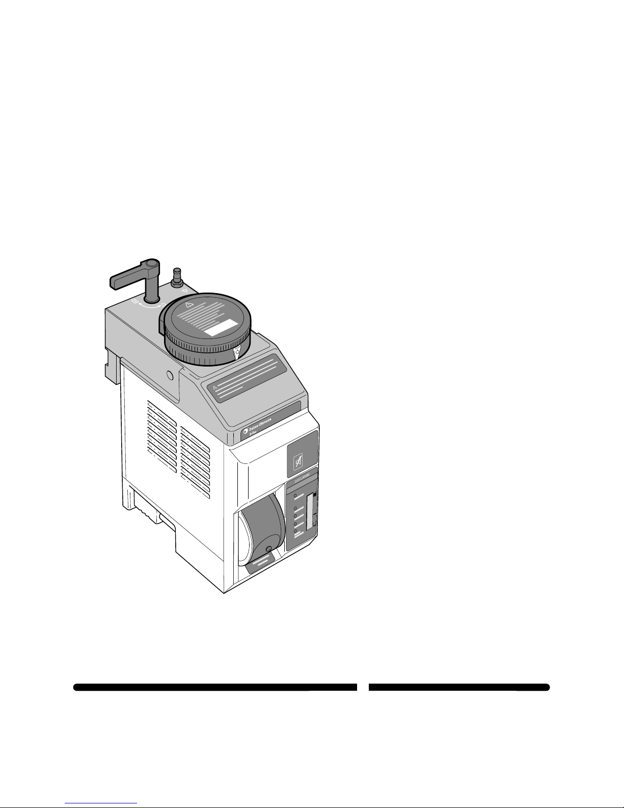
2.0 Description
2.1 General
TheD-TecVaporizer is designedto add Suprane™(desflurane) inhalant anestheticvaporto the medicalgases supplied
toapatient. The vaporizermust only bemounted on aDrägercompatible anesthesia machinewhich is equippedwith
aninterlockingtype manifold. Thevaporizer must besupplied with dry medicalgas and itmust be connectedtoa
suitableelectricalmains supply. However theD-Tec vaporizer cannotbe used on theNarkomed Mobile anesthesia
system.
TheD-TecVaporizer is designedto meet UL2601-1, IEC 601-1andIEC 601-2-13 recommendations.
Whenthevaporizer is connectedto the electricalsupply, the dial isturned to theq(Stand-by) symboland the green
OPERATIONALlightlocated on thefront display panelis illuminated, thevaporizeris in theelectrical stand-by condition
andisready for use,as described inSection 5.0 OperatingInstructions.

D-Tec Vaporizer Page 3
O & M Manual Part No. 1107-0622-000 August 2001
Mechanicalandelectrical interlocks areincorporated into thevaporizer to helpensurethat the followingcriteria are
satisfied:
1. The vaporizer dial can only beturned from qwhenthevaporizer is lockedonto the manifoldandthe green
OPERATIONALlightis illuminated toindicate that thevaporizer has attainedthecorrect operating temperature.
2. Thegasflow only entersthe vaporizer whichis in operation.
3. Unwantedanesthetictrace vapor isminimized after avaporizer is turned toq.
Note: It is a requirement of the ASTM standard F1850-98 and European Standard EN 740 - Anaesthetic
Workstations And Their Modules, that an appropriate gas monitor is used to monitor the concentration of
anaesthetic agent vapor in the inspiratory gas when the vaporizer is in operation, in order to provide
protection against hazardous output in the event of a device malfunction.
wWarning: This manual and all its associated documentation must be studied before any attempt is
made to install, operate or clean any part of the D-Tec Vaporizer.
wWarning: The performance of the anesthetic machine and vaporizer may be degraded if the machine
and vaporizer are mismatched.
wWarning: Do not install a D-Tec vaporizer in the right hand position of a Narkomed 6000 as this will
result in an incorrect fit and may cause leaks in the fresh gas delivery system.
wWarning: To avoid explosive hazards, flammable anesthetic agents such as Ether and Cyclopropane
must not be used in this vaporizer. Only anesthetic agents which comply with the requirements for non-
flammable anesthetic agents in the IEC 601-2-13 Standard, particular requirements for the safety of
anesthesia machines, are suitable for use in the presence of this vaporizer.
wWarning: As this vaporizer is not suitable for use with flammable anesthetic agents such as Ether or
Cyclopropane, the use of antistatic breathing tubes and face masks is not necessary. The use of
antistatic or electrically conductive breathing tubes when utilizing high frequency electric surgery
equipment may cause burns and is therefore not recommended in any application of this vaporizer.
wWarning: The functioning of this vaporizer may be adversely effected by the operation of equipment
such as high frequency surgical apparatus or short-wave therapy equipment in the vicinity.
wWarning: Do not operate the vaporizer other than with dry medical gases.
wWarning: The D-Tec Vaporizer must not be used in a Magnetic Resonance Imaging environment.
wWarning: The functioning of this D-Tec vaporizer may be adversely affected by electromagnetic
interference exceeding the levels specified in EN 60601-1-2.
wWarning: This product contains a small quantity of Mercury in the Tilt Switch mechanism and should be
disposed of according to local regulations.
wCaution: If the vaporizer is not likely to be used for a period of 12 months, the battery must be
removed. Failure to do so may result in damage to the vaporizer.
wCaution: 'No Output' alarm could be caused by downstream high frequency ventilation at greater than
60 breaths/min with an airway pressure of 100 cm H2O or pulsing the O2flush faster than 1 pulse/sec
over a time period of greater than 10 secs.
wCaution: Refer to the User’s Manual for the Dräger Julian Anaesthesia Workstation for recommended
ventilator parameter limitations when using the D-Tec with a Julian.
Page 4 D-Tec Vaporizer
August 2001 O & M Manual Part No. 1107-0622-000
Use Only
Desflurane
2.2 Component Information
2.2.1 Power Supply Unit
The D-Tec Vaporizer uses a 100 to 120V a.c. 50/60 Hz electrical supply model. A label on the rear panel of
the vaporizer states the voltage requirement for each model.
The integral power supply unit consists of a transformer and an a.c. to d.c. converter which provides the
12V d.c. and 5V d.c. supplies for the electrical system.
2.2.2 Filler Assembly
The filler assembly, illustrated on Fig. 1,
incorporates an agent specific fitting which
helps to ensure that only a Suprane™
(desflurane) specific bottle equipped with a
"Saf-T-Fill"™valve can be inserted in order
to fill the vaporizer.
POWER SUPPLY
CONNECTOR
BATTERY
COVER
FILLER
ASSEMBLY
FILLER
PORT
FILLER
LABEL
AA.43.037
AA.43.055
Fig. 2 Vaporizer Base
Fig. 1 Filler Assembly
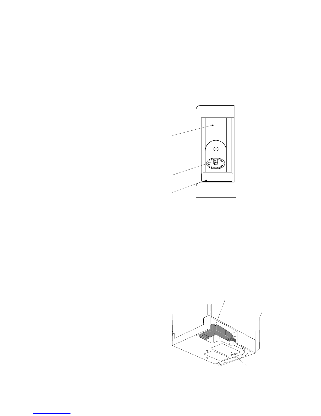
2.2.3 Drain Plug
wWarning: Draining the vaporizer may result in rapid loss of pressure and/or agent which could lead to
injury to the operator.
A drain plug is located at the base of the vaporizer as illustrated on Fig. 2. The drain plug must not be
removed except at an Datex-Ohmeda Authorized Service Center.
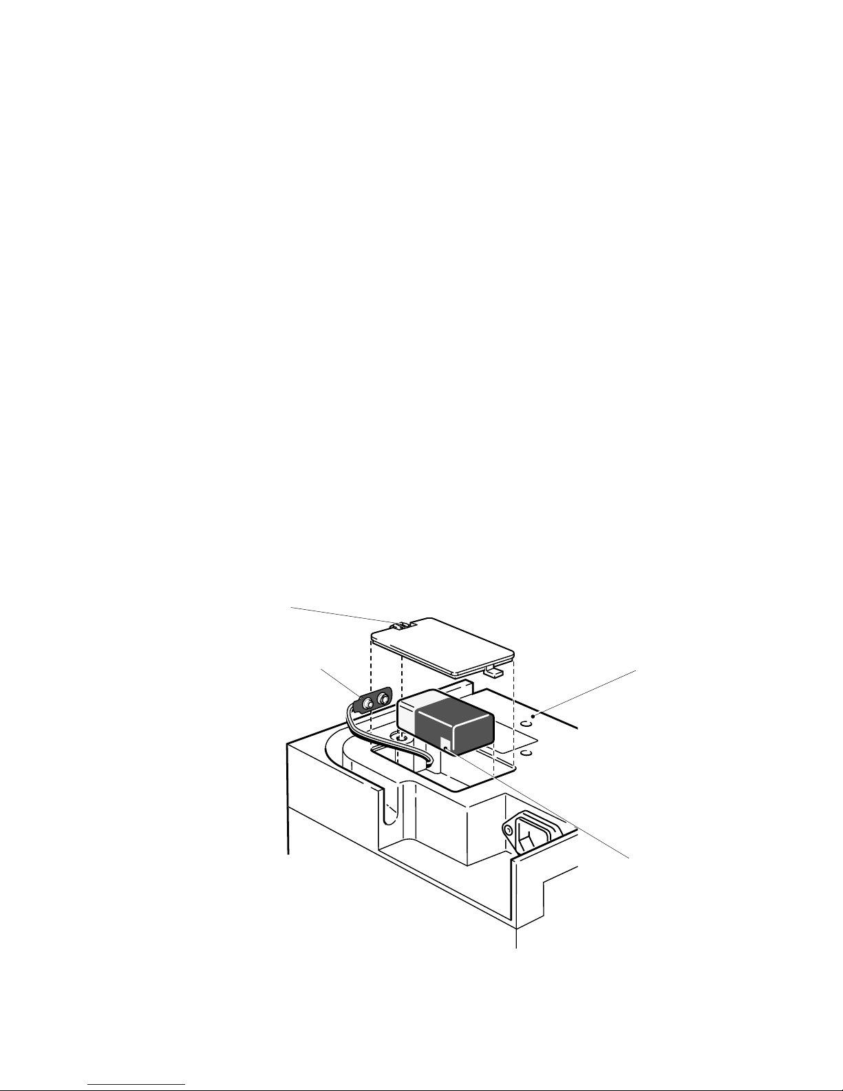
2.2.4 Power Supply Connector And Battery
The electrical power supply connector is located in
the base of the vaporizer as illustrated on Fig. 2.
If the mains power supply fails, a Duracell 1604
or VARTA Energy 2000 battery incorporated in
the base of the vaporizer provides power for the
auditory and visual alarms only. The battery
must be replaced annually.

D-Tec Vaporizer Page 5
O & M Manual Part No. 1107-0622-000 August 2001
2.2.5 Equi-Potential Stud
The equi-potential stud Yis located on the top of the vaporizer. It provides a means of connecting a
vaporizer to the anesthesia system to minimize any electrical potential difference between the vaporizer
casing and the anesthesia system.
2.2.6 Sump
The sump provides a means of containing the agent and includes the agent filling port, the drain, the
heaters and the agent level sensor.
The sump has a total nominal capacity of 390 milliliters (ml) which consists of a nominal 330 ml indicated
volume and a nominal 60 ml reserve.
2.2.7 Heater Elements
Two 100W heater elements, located in the base of the sump, heat the agent to a nominal 39°C (102°F) to
generate the working pressure.
Two 100W heater elements located in the upper part of the vaporizer help to prevent condensation of the
anesthetic agent in the vaporizer.
The current supplied to power the heaters alternates between the two heaters in the sump and the two
heaters in the upper part of the vaporizer. This minimizes the current requirement.
The casing of the vaporizer is normally warm to the touch while it is connected to the electrical supply.
2.2.8 Monitors
Electro/mechanical monitors are incorporated to monitor the fresh gas/agent vapor pressure balance and
the agent volume.
The monitors control the operational status display and activate the appropriate alarm indication if a
monitored parameter malfunction is detected.
2.2.9 Agent Level Sensor
An agent level sensing probe is mounted in the sump to measure the agent level. When the sump contains
between 60 and 390 ml of agent, the LCD level display indicates the level of agent in the sump. If the agent
level decreases below 60 ml, the amber LOW AGENT light on the display panel flashes and the auditory
alarm is activated. If the agent level decreases below approximately 20 ml,
the red NO OUTPUT light flashes and the auditory alarm is activated. Vapor output then ceases.
2.2.10 Tilt Switch
If the vaporizer is tilted for 10-15 seconds while it is in operational mode and delivering vapor, vapor
delivery will be stopped, as indicated by the flashing No Output light and auditory alarm.
Page 6 D-Tec Vaporizer
August 2001 O & M Manual Part No. 1107-0622-000
DESFLURANE
NO OUTPUT
LOW AGENT
ALARM
BATTERY LOW
WARM-UP
OPERATIONAL
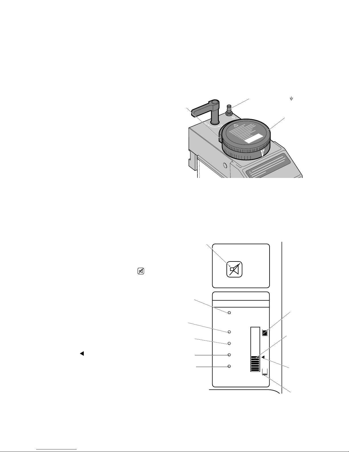
3.0 Controls And Indicators
3.1 Dial Assembly
The manually operated dial is used to select the level of agent concentration from 1% to 18%. The dial is
marked at intervals of 1% from 1% to 10% and at intervals of 2% from 10% to 18%. Selections can be
made at any setting between 1% and 18%.
The dial release incorporated in the dial
assembly must be operated in order to turn
the dial from the q(Standby) setting and it
must be operated again to turn the dial from
12% to a higher % setting. All other
settings can be made without operating the
dial release.
A solenoid interlock mechanism is also
incorporated to help to ensure that the dial
can be operated only when the green
OPERATIONAL light located on the display
panel is illuminated.
Fig. 3 Dial Assembly
3.2 Auditory And Visual Indicators
Visual indicators and an auditory alarm are used to provide the vaporizer status display and also to indicate
an alarm condition, as described in Section 3.3.
Visual indicators are located on the front
display panel illustrated in Fig. 4 and the
auditory alarm is mounted behind the
upper part of the front display panel.
An auditory alarm mute button located
above the display panel can be used to
mute the alarm temporarily under certain
conditions as described in Sections 3.3,
3.3.4 and 3.3.5.
The LCD agent level display indicates the
level of agent contained in the vaporizer
sump, as described in Section 3.3.3. The
range of indication is between a minimum
of 60 ml and a maximum of 390 ml. When
the indication is below the 240 ml refill
mark , illustrated in Fig. 4, it indicates
that an additional 240 ml of agent can be
added.
60 ml
NOMINAL
RED
DIAL
DIAL
RELEASE
AUDITORY ALARM
MUTE BUTTON
390 ml
NOMINAL
LCD AGENT
LEVEL
DISPLAY
240 ml
REFILL
MARK
GREEN
AMBER
AMBER
AMBER
EQUI-POTENTIAL STUD
AB.54.001
AA.43.038
Fig. 4 Front Display Panel
D-Tec Vaporizer Page 7
O & M Manual Part No. 1107-0622-000 August 2001
3.3 Status Display
The display panel lights and the auditory alarms operate as follows to indicate the operational status of the
vaporizer:
Note: If the dial is at the
q
setting when an alarm occurs, the auditory alarm is activated and the light
indicating the alarm condition flashes. When the is pressed, the auditory alarm is muted and the light
is continuously illuminated.
3.3.1 Warm-Up
The amber WARM-UP light is continuously illuminated when the
vaporizer is in its warm-up mode. The dial cannot be turned
from qwhen the vaporizer is in its warm-up mode.
AA.43.039
DESFLURANE
NO OUTPUT
LOW AGENT
ALARM
BATTERY LOW
WARM-UP
OPERATIONAL
DESFLURANE
NO OUTPUT
LOW AGENT
ALARM
BATTERY LOW
WARM-UP
OPERATIONAL
Fig. 5 Warm-Up
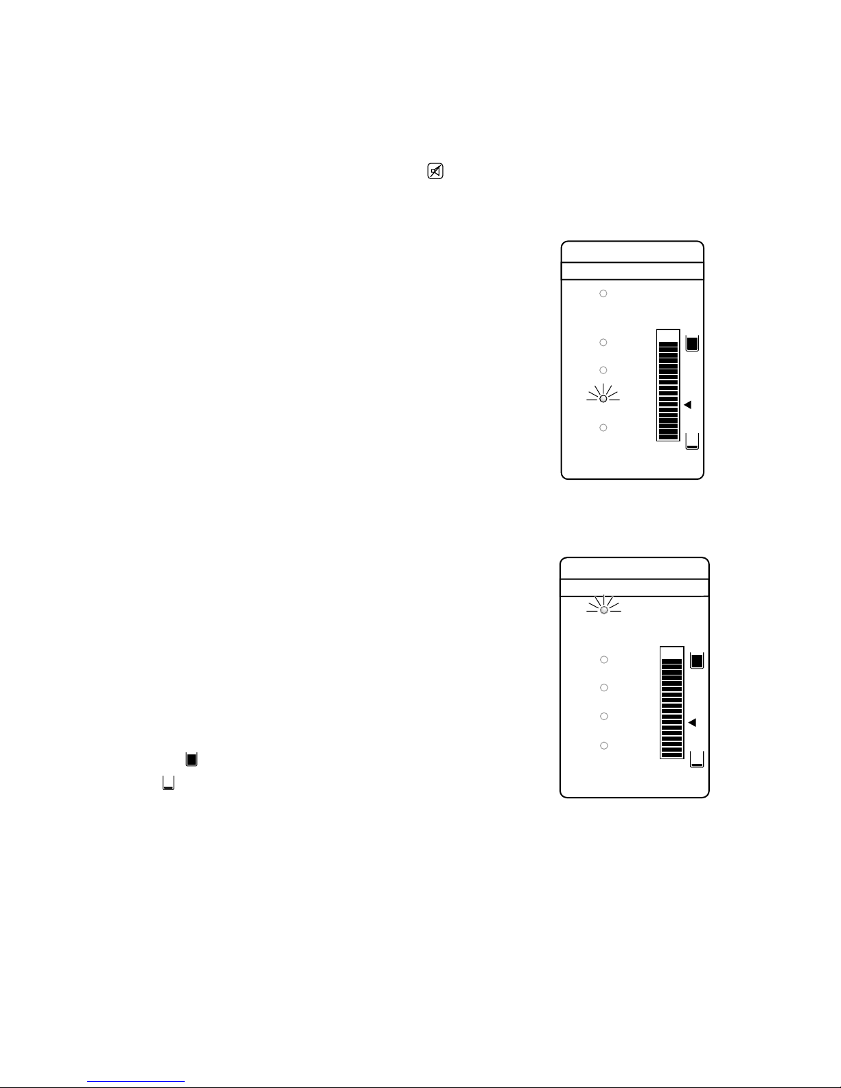
3.3.2 Operational
The green OPERATIONAL light is continuously illuminated
when the vaporizer is in its operational mode. The dial can be
turned from the qsetting when the vaporizer is in the
operational mode.
3.3.3 Agent Level Display
The LCD agent level display consists of a series of bars which
indicate the nominal volume of agent in the vaporizer sump.
The symbol denotes a 390 ml volume of agent and the
symbol denotes a 60 ml volume of agent in the sump.
Fig. 6 Operational
As the sump fills, the first agent level indicating bar appears in the LCD volume display when there is
between 60 and 80 ml of agent in the sump. As the level increases more bars are displayed as illustrated on
Fig. 6 and as the level decreases less bars are displayed.
When the bars are either level with or below the <, the sump can accommodate 240 ml of agent, which is
one full bottle. When there are no bars visible, as illustrated on Fig. 7, the Low Agent Level alarm is
activated as described in Section 3.3.4.
Note: The agent level display is calibrated to be most accurate when the vaporizer is in a perfectly level
position. Deviations from a level position affect the accuracy of the agent level display and may activate the
LOW AGENT level alarm.
AA.43.040

Page 8 D-Tec Vaporizer
August 2001 O & M Manual Part No. 1107-0622-000
3.3.4 Low Agent Level
The amber LOW AGENT light flashes accompanied by a
long tone operation of the auditory alarm which is a
repetitive 1.5 seconds ON and 0.5 seconds OFF. The
alarm indicates that there is less than 60 ml of agent
remaining in the sump.
Pressing the mutes the auditory alarm for a period of 120
seconds to allow time to fill the vaporizer to above 60 ml.
If a LOW AGENT condition occurs during normal
operation, the alarm is activated but the green
OPERATIONAL light remains illuminated.
Fig. 7 Low Agent Level
3.3.5 No Output
The NO OUTPUT alarm is activated if any one of the
following occurs:
1. The agent level decreases to below 20 ml.
2. The vaporizer is tilted.
3. A power failure of longer than 10 seconds duration occurs.
4. An internal malfunction is detected.
The alarm consists of a flashing red NO OUTPUT light
accompanied by short tone operation of the auditory alarm
which is a repetitive 0.5 seconds ON and 0.5 seconds OFF.
The alarm indicates that the vaporizer has closed down and
is no longer delivering any vapor.
Fig. 8 No Output
If the NO OUTPUT alarm occurs while the vaporizer is in use, the vaporizer dial must be turned to q. This
mutes the auditory alarm and illuminates the red light continuously. Either an alternative vaporizer or an
alternative method of anesthesia must be used.
If the NO OUTPUT alarm is activated as a result of a power failure and
the dial is at qwhen the power supply is restored, the alarm and
display test is activated and then the vaporizer returns to either the
WARM-UP or the OPERATIONAL mode.
If the dial is not at qwhen the power supply is restored, the NO
OUTPUT alarm continues and can only be cancelled by turning the dial
to q. In this condition the alarm and display test is not activated and
the vaporizer returns to either the WARM-UP or the OPERATIONAL
mode after a 10 second delay.
3.3.6 Alarm Battery Low
The amber ALARM BATTERY LOW light continuously illuminates to
indicate that the alarm battery voltage is low. A new battery must be
fitted within eight hours to support the NO OUTPUT alarm in the
event of a subsequent mains failure condition. There is no auditory
alarm in the ALARM BATTERY LOW condition. Fig. 9 Alarm Battery Low
AA.43.041
AA.43.042
AA.43.043
DESFLURANE
NO OUTPUT
LOW AGENT
ALARM
BATTERY LOW
WARM-UP
OPERATIONAL
DESFLURANE
NO OUTPUT
LOW AGENT
ALARM
BATTERY LOW
WARM-UP
OPERATIONAL
DESFLURANE
NO OUTPUT
LOW AGENT
ALARM
BATTERY LOW
WARM-UP
OPERATIONAL
D-Tec Vaporizer Page 9
O & M Manual Part No. 1107-0622-000 August 2001
DURACELL
DURACELL
mn 623r
4.0 Vaporizer Preparation
4.1 Fitting The Battery And The Mains Lead
wCaution: Do not support the vaporizer by holding the control dial and/or locking lever. Hold the main
body of the vaporizer with both hands and keep the vaporizer in an upright position. Failure to do so
may cause the vaporizer to malfunction.
wCaution: Only a Duracell 1604 or VARTA Energy 2000, 9 Volt battery must be installed in the
vaporizer. If any other battery is installed, it may damage the vaporizer.
wWarning: The battery terminals must be firmly clipped onto the battery to help prevent a possible
disconnection when the vaporizer is moved.
wWarning: Only a Datex-Ohmeda mains lead must be used to connect the vaporizer to the electrical
supply.
wWarning: When routing the mains lead to the electrical supply, ensure that it does not interfere with
the correct functioning of other equipment.
The new battery and the mains lead supplied with the vaporizer must be fitted during initial installation
as detailed in Instructions 1, 2 and 3, therefore Instructions 1, 2 and 3 can be ignored if a battery and
mains lead are already fitted.
1. Invert the vaporizer, unscrew the battery cover securing screw and remove the battery cover from
the base of the vaporizer as illustrated on Fig. 10.
2. Clip the battery terminals firmly onto the new battery observing the correct polarity. Insert the
battery into the vaporizer, fit the battery cover to the base of the vaporizer and tighten the securing
screw.
Fig. 10 Fitting The Battery
BATTERY
TERMINALS
BATTERY COVER
SECURING SCREW
VAPORIZER
INVERTED
DURACELL 1604 OR VARTA
ENERGY 2000 BATTERY
AA.43.044

Page 10 D-Tec Vaporizer
August 2001 O & M Manual Part No. 1107-0622-000
3. Remove the mains lead retaining plate illustrated on Fig. 11 and fit the Datex-Ohmeda mains lead
firmly into the socket of the vaporizer. Feed the mains lead into the mains lead channel and then clip
the mains lead retaining plate back into the base.
4. Feed the lead round the back of the vaporizer.
Fig. 11 Fitting The Mains Lead
4.2 Vaporizer Installation
Connecting the vaporizer to the plug-in system
wCaution: Use only the Dräger plug-in system!
1. Set the control dial to the qposition.
On commissioning only:
•Remove protective plugs from
vaporizer's ports.
2. Install the ‘O’rings, if necessary, as
described in the relevant anesthesia machine
operation and maintenance manual.
3. The locking lever must be set to the “unlocked”position.
•With both hands, hold the main body of the vaporizer in an
upright position and lower it on to the plug-in system,
ensuring that the vaporizer ports correctly engage the
plug-in system port valves.
•To lock the vaporizer, turn the locking lever 90°in a
clockwise direction.
The vaporizer should lie positioned horizontally on the
plug-in system.
wWarning: Do not install a D-Tec vaporizer in the right hand
position of a Narkomed 6000 as this will result in an incorrect fit
and may cause leaks in the fresh gas delivery system.
MAINS LEAD
CHANNEL
MAINS LEAD
MAINS LEAD
RETAINING PLATE
AB.54.002
2
2
3
1
AB.54.010
AB.54.009

D-Tec Vaporizer Page 11
O & M Manual Part No. 1107-0622-000 August 2001
Fitting the equi-potential lead
e.g. for intracardiac
•Fit one end of the lead to the equi-potential stud on
the D-Tec.
•Route and connect the other end of the lead to a
central ground stud, as described in the relevant
anesthesia machine Operation and Maintenance
Manual.
DESFLURANE
NO OUTPUT
LOW AGENT
ALARM
BATTERY LOW
WARM-UP
OPERATIONAL
5.0 Operating Instructions
5.1 Alarm And Display Test
wWarning: Only use vaporizers which are in a serviceable condition.
wCaution: Allow the vaporizer to attain its specified ambient operating temperature before connecting it
to a mains power supply.
1. Connect the mains lead from the vaporizer to an approved hospital grade outlet socket.
wWarning: Do not use the vaporizer if during the alarm and display test any one of the five lights and all
the LCD agent level indicator bars do not flash or the auditory alarm does not operate for a period of
approximately two seconds.
2. Verify that the alarm and display test is automatically operated for a period of approximately two
seconds as follows:
a) Each light and all the LCD agent level
indicator bars on the front display
panel flash four times.
b) The auditory alarm is activated four
times.
3. The alarm and indicators can be tested at any time
by pressing the for at least four seconds to
activate the alarm and display test. Activating the
test does not affect the operation of the vaporizer.
4. The alarm and display test is designed to test the
lights, the LCD bars and the auditory alarm. If any
of the lights, the LCD bars and/or the auditory
alarm fail to operate, do not use the vaporizer.
Fig. 12 Alarm And Display Test
AA.43.048 AB.54.005
w
D-Tec

Page 12 D-Tec Vaporizer
August 2001 O & M Manual Part No. 1107-0622-000
wCaution: If there are no LCD bars visible and the amber LOW AGENT light is illuminated after the alarm
and display test is completed, there is less than 60 ml of agent in the sump and the vaporizer must be
filled as described in Section 5.4.
5. If the LOW AGENT light remains illuminated after the alarm
and display test is completed, fill the vaporizer as described
in Section 5.4.
6. If there is sufficient agent in the sump, check that each light
is extinguished, except the amber WARM-UP light which
indicates that the vaporizer is in its warm-up condition. If the
vaporizer is warm before it is connected to the electrical
supply the green OPERATIONAL light may illuminate
immediately.
AA.43.039
AA.43.040
DESFLURANE
NO OUTPUT
LOW AGENT
ALARM
BATTERY LOW
WARM-UP
OPERATIONAL
DESFLURANE
NO OUTPUT
LOW AGENT
ALARM
BATTERY LOW
WARM-UP
OPERATIONAL
Fig. 13 Amber WARM-UP Light
7. After a warm-up period of up to 10 minutes check that the
amber WARM-UP light extinguishes and the green
OPERATIONAL light illuminates to indicate that the vaporizer
is ready for use.
8. If the OPERATIONAL light does not illuminate within 10
minutes, refer to Section 8.0 Fault Diagnosis.
Fig. 14 Green OPERATIONAL Light
5.2 Preoperative Checkout
1. Perform the leak test as described in the relevant anesthesia system's Operation And Maintenance
Manual initially with the dial at q. Repeat the test with the vaporizer dial turned to the 1% setting and
then turn the dial to the qsetting.
2. Check the amber ALARM BATTERY LOW light. If the light is illuminated, fit a new battery as described
in Section 6.2 and check that the light extinguishes.
3. Turn the dial to a setting of 1% or above and then isolate the vaporizer from the electrical supply by
disconnecting the mains lead from its outlet socket.
4. Wait for at least 15 seconds and then check that both the auditory alarm and the red NO OUTPUT light
are activated.
5. If the alarm and light are not activated, do not use the vaporizer until the fault is rectified.
6. When the alarm and light are activated, turn the dial to the qsetting, reconnect the mains lead and
check that the alarm and display test is activated.
7. When the green OPERATIONAL light illuminates, continue operation.

D-Tec Vaporizer Page 13
O & M Manual Part No. 1107-0622-000 August 2001
5.3 Turning The Dial To The Required Setting
wWarning: High % dial settings combined with low gas flows may lead to hypoxic mixtures within the
breathing circuit. Datex-Ohmeda strongly recommends the use of oxygen monitoring.
wWarning: The dial release must be operated to turn the dial from the qq
qq
qsetting and also to increase
the dial setting to above 12%. Do not operate the dial release when turning the dial to any other
setting, it may result in overriding the 12% stop and causing an inadvertent delivery in excess of 12%.
wWarning: The vaporizer has not been calibrated at any dial setting between qq
qq
qand 1%. Do not use the
vaporizer at dial settings between qq
qq
qand 1%.
wWarning: It is a requirement of the ASTM Standard F1850-98 and the European Standard EN 740 -
Anaesthetic Workstations And Their Modules, that the gas monitoring device referred to in Section 2.1
of this manual is in operating condition, by being enabled and functioning, prior to use of the
vaporizer.
1. Operate the dial release and turn the dial in a counter-clockwise direction from the qsetting, as
illustrated in Fig. 15.
2. Release the dial release and turn the dial to the required percentage setting.
AB.54.007
Fig. 15 Turning The Vaporizer Dial
3. Check that when the vaporizer dial is turned from the qsetting, the dial of no other vaporizer mounted
on the same manifold can be turned.
4. Turn the dial to the qsetting and check that the dial release springs out.
Note: The vaporizer will remain in standby
q
, ready for further use if required, until the electrical supply is
disconnected.
DIAL RELEASE

Page 14 D-Tec Vaporizer
August 2001 O & M Manual Part No. 1107-0622-000
D
DESFLURANE
PUSH BOTTLE FIRMLY
INTO FILLER PORT
BOTTLE CAP
'O' RING
AA.43.050
5.4 Filling The Vaporizer
5.4.1 General
wWarning: Do not fill the vaporizer with any substance other than Suprane™ (desflurane). If any
substance other than Suprane™ (desflurane) is used, patient injury could occur.
wWarning: When the vaporizer is in use, do not fill the vaporizer if the following conditions apply:
• The dial setting is more than 8% at flows of 8 liters/minute or above.
• The vaporizer is subjected to any high back pressure.
• The Suprane™ (desflurane) has been refrigerated or chilled below 18°C.
Failure to comply with this warning may result in a temporary decrease in delivered concentration and
activate the NO OUTPUT alarm.
wWarning: The vaporizer must be filled when it is in an upright position. Failure to do so may result in
the vaporizer being over filled.
wWarning: The vaporizer must only be filled when it is connected to the electrical supply. This enables
the agent level on the agent level display to be observed. Do not attempt to fill the vaporizer when the
level display indicates that it is full.
The D-Tec Vaporizer must only be filled when it is in an upright position. The vaporizer sump can be filled
when the vaporizer is in its WARM-UP cycle, or at any time the vaporizer is in use. If the vaporizer is in its
OPERATIONAL condition, the time taken for the agent to flow into the vaporizer may be increased. Only
agent bottles with a "Saf-T-Fill"™bottle probe specific to Suprane™(desflurane) should be inserted into the
filler port.
5.4.2 Filling Procedure
1. Remove the bottle cap from the Suprane™(desflurane) bottle and ensure that the 'O' ring is correctly
fitted to the bottle probe.
2. Insert the bottle probe into the filler port as illustrated in Fig. 16 and then push the bottle firmly against
the spring pressure until it is fully engaged with the filler port.
Fig. 16 Inserting The Bottle

D-Tec Vaporizer Page 15
O & M Manual Part No. 1107-0622-000 August 2001
wWarning: Ensure that the bottle probe is fully engaged into the filler port before attempting to lift the
bottle. If the bottle cannot easily be lifted, do not force it otherwise the valve may be broken.
3. When the probe cannot be inserted any further into the filler port, attempt to lift the bottle upwards.
4. If the bottle cannot easily be lifted it may be because the bottle has not been completely inserted,
therefore firmly push the bottle straight into the filling port to its full extent to make sure that it is fully
inserted.
5. When the bottle moves easily, lift it upwards to lock the bottle onto the filler port as illustrated in Fig. 17.
6. When the bottle reaches the upper stop, bubbling of agent in the bottle will occur for a period of up to
45 seconds before the agent flows from the bottle through the filler port into the vaporizer sump.
7. Hold the bottle in position at the upper stop and fill until the bottle is empty or the indicator on the
front display panel indicates that the sump is full.
ENSURE BOTTLE IS
FULLY ENGAGED IN
FILLER PORT LIFT BOTTLE
UPWARDS TO FILL
AB.54.004
Fig. 17 Filling The Vaporizer
wWarning: Grip the bottle firmly while rotating it downwards from the upper stop position to the lower
stop position and hold the bottle firmly in the filler port until the small amount of agent in the filler
system has drained back into the bottle. Failure to do so may result in spilling agent.
8. Grip the bottle firmly and lower it from the upper stop position to the lower stop position.
9. When the bottle reaches the lower stop position, hold the bottle firmly in the filler port for a minimum
of 5 seconds to allow the small amount of agent in the filler system to drain back into the bottle.
10. To avoid dropping the bottle, support the bottle as it is automatically unlocked from the filler port and
released from the filler.
11. The valve on the bottle automatically closes to help avoid loss of agent.
AB.54.006
This manual suits for next models
1
Table of contents
Other Datex-Ohmeda Vaporizer manuals


