Datex-Ohmeda Tec 5 User manual

Tec 5 Continuous
Flow Vaporizer
Operation and Maintenance Manual

User Responsibility
This Product will perform in conformity with the description thereof contained in this
operating manual and accompanying labels and/or inserts, when assembled, operated,
maintained and repaired in accordance with the instructions provided. This Product
must be checked periodically. A defective Product should not be used. Parts that are
broken, missing, plainly worn, distorted or contaminated should be replaced
immediately. Should such repair or replacement become necessary, Datex-Ohmeda
recommends that a telephonic or written request for service advice be made to the
nearest Datex-Ohmeda Field Service Support Center. This Product or any of its parts
should not be repaired other than in accordance with written instructions provided by
Datex-Ohmeda and by Datex-Ohmeda trained personnel. The Product must not be
altered without the prior written approval of Datex-Ohmeda’s Quality Assurance
Department. The user of this Product shall have the sole responsibility for any
malfunction which results from improper use, faulty maintenance, improper repair,
damage, or alteration by anyone other than Datex-Ohmeda.
CAUTION wU. S. Federal and Canadian law restrict this device to sale by or on the order of
a licensed medical practitioner. Outside the U. S. A. and Canada, check local
laws for any restrictions that may apply.
Datex-Ohmeda products have unit serial numbers with coded logic which indicates a
product group code, the year of manufacture and a sequential unit number for
identification.
AAA A 12345
This alpha character indicates the year of product manufacture
and when the serial number was assigned; “Y” = 1995, “Z” = 1996,
“A” = 1997, etc. “I” and “O” are not used.
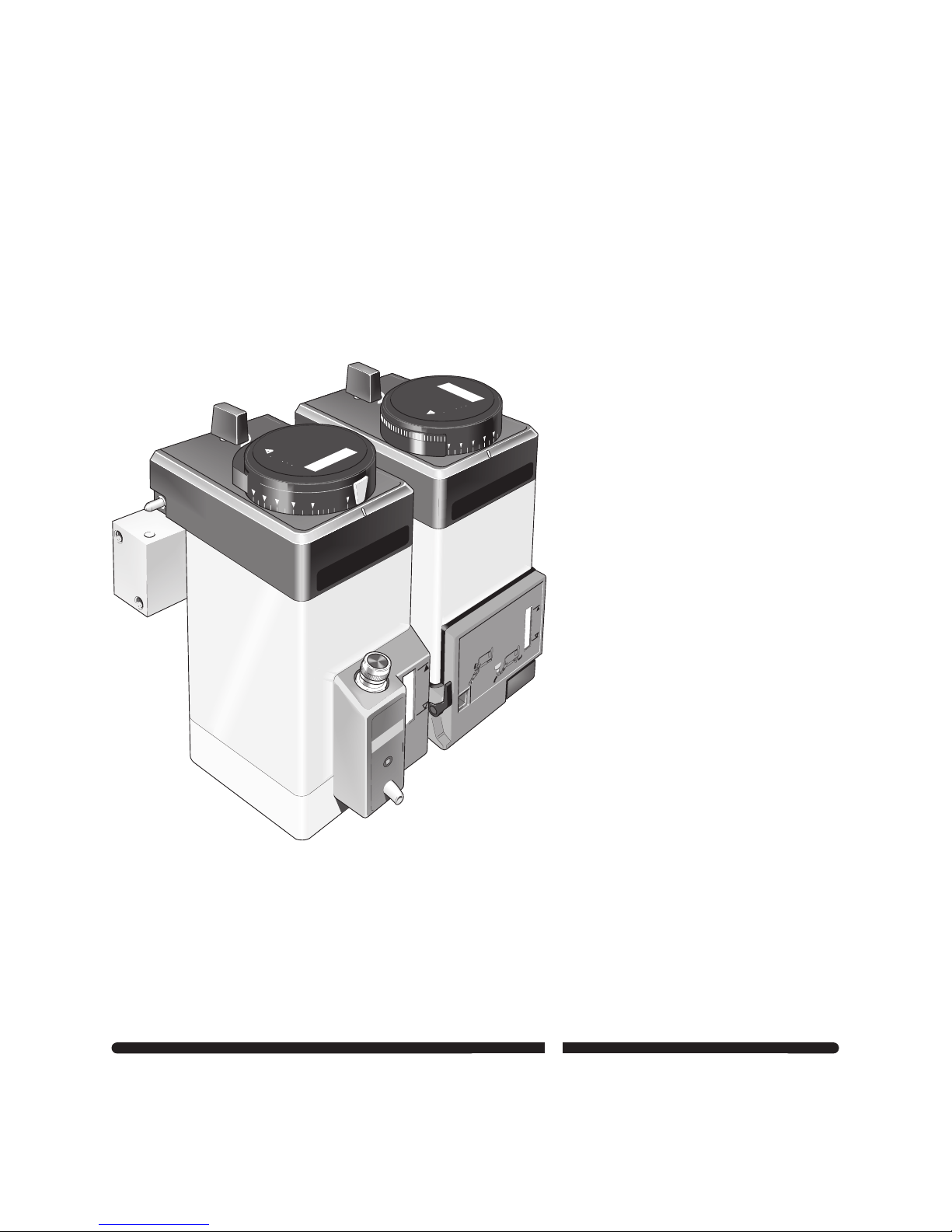
Tec 5 Continuous
Flow Vaporizer
Lock
before
use
2
Warning
Keep upright at all times
See manual for
Operational Instructions.
Factors affecting performance.
Service and maintenance
recommendations
Next service date
!
Use Only Isoflurane
3
4
5
1
.8
Lock
before
use
Use Only
Enflurane
1
2
3
4
5
0%
.8
.6
.4
.2
Warning
Keep upright at all times
See manual for
Operational Instructions.
Factors affecting performance.
Service and maintenance
recommendations
Next service date
!
Of

Contents
Page
1.0 Introduction .................................................... 1
1.1 Operation And Maintenance Manual......................................................1
1.2 Precautions.............................................................................................1
1.3 Symbols..................................................................................................1
2.0 Servicing Policy ............................................... 2
3.0 Description ..................................................... 3
3.1 General....................................................................................................3
3.2 Control Dial.............................................................................................3
3.3 Safety Interlocks.....................................................................................3
3.4 Vaporizer Identification Label................................................................4
4.0 Operating Instructions ........................................ 4
4.1 General....................................................................................................4
4.2 Vaporizer Mounting Procedure..............................................................5
4.3 Checking For Correct Mounting Of The Vaporizer................................6
4.4 Turning ON The Vaporizer......................................................................6
4.5 Vaporizer Removal.................................................................................6
4.6 Filling And Draining................................................................................7
4.6.1 General....................................................................................................7
4.6.2 Filling A Vaporizer Which Incorporates A Screw Cap Filler..................7
4.6.3 Draining A Vaporizer Which Incorporates A Screw Cap Filler..............8
4.6.4 Filling A Vaporizer Which Incorporates A Keyed Filler..........................9
4.6.5 Draining A Vaporizer Which Incorporates A Keyed Filler...................10
4.6.6 Filling A Vaporizer Which Incorporates A Quik-Fil™ Filler.................11
4.6.7 Draining A Vaporizer Which Incorporates A Quik-Fil™ Filler..............12
5.0 Maintenance ..................................................13
5.1 Schedule...............................................................................................13
5.1.1 Every Two Weeks.................................................................................13
5.1.2 Every Three Years................................................................................13
5.2 Cleaning................................................................................................13
5.3 Contamination......................................................................................14
5.4 Repairs..................................................................................................14
6.0 Principle Of Operation .......................................15
6.1 Interlock Mechanism............................................................................15
6.2 Selectatec Series Mounted Manifold Gas Circuit................................17
6.3 Vaporizer Valve And Sump Assembly.................................................18
6.4 Gas Flow Through The Vaporizer.........................................................19
6.4.1 General..................................................................................................19
6.4.2 By-pass Circuit.....................................................................................19
6.4.3 Vaporizing Chamber Circuit.................................................................19
7.0 Performance ..................................................21
7.1 Performance Curves.............................................................................21
7.1.1 Isotec 5%..............................................................................................21
7.1.2 Fluotec 5%............................................................................................22
7.1.3 Enfluratec 5%.......................................................................................23
7.1.4 Sevotec 5%...........................................................................................24
7.1.5 Sevotec 8%...........................................................................................25
7.2 Effects Of Variables..............................................................................26
7.2.1 Anaesthetic Agent Consumption.........................................................26
7.2.2 Temperature.........................................................................................26
Tec 5 Vaporizer Contents 1
O & M Manual Part No. 1105-0100-000 August 1999

Contents 2 Tec 5 Vaporizer
August 1999 O & M Manual Part No. 1105-0100-000
Contents
Page
7.2.3 Barometric Pressure............................................................................26
7.2.4 Back Pressure (Steady)........................................................................27
7.2.4.1 Low And Moderate Pressures27
7.2.4.2 High Pressures 27
7.2.5 Back Pressure (Fluctuating).................................................................27
7.2.6 Carrier Gas Composition......................................................................27
7.2.7 Time Out Of Service.............................................................................27
7.2.8 Other Variables.....................................................................................28
8.0 Checking The Calibration ...................................28
9.0 Analytical Techniques .......................................29
10.0 Specification ..................................................30
10.1 Calibration.............................................................................................30
10.2 Resistance To Gas Flow With Vaporizer Out Of Circuit......................30
10.3 Liquid Capacity.....................................................................................30
10.4 Weight And Dimensions......................................................................30
10.5 Environmental Conditions....................................................................30
10.6 Performance.........................................................................................30
11.0 Warranty .......................................................31
Illustrations
Fig. 1 Vaporizer Identification Label................................................................4
Fig. 2 Vaporizer Mounting Procedure..............................................................5
Fig. 3 Locking The Vaporizer On To A Manifold..............................................5
Fig. 4 Turning ON The Vaporizer......................................................................6
Fig. 5 Unlocking The Vaporizer From A Manifold............................................6
Fig. 6 Filling A Vaporizer Which Incorporates A Screw Cap Filler..................7
Fig. 7 Draining A Vaporizer Which Incorporates A Screw Cap Filler..............8
Fig. 8 Filling A Vaporizer Which Incorporates A Keyed Filler..........................9
Fig. 9 Draining A Vaporizer Which Incorporates A Keyed Filler...................10
Fig.10 Filling A Vaporizer Which Incorporates A Quik-Fil™ Filler.................11
Fig.11 Draining A Vaporizer Which Incorporates A Quik-Fil™ Filler.............12
Fig.12 Vaporizer Interlock Mechanism...........................................................15
Fig.13 Two Vaporizers Locked On To The Manifold -
Both Turned OFF...................................................................................16
Fig.14 Two Vaporizers Locked On To The Manifold -
Vaporizer A Turned ON........................................................................16
Fig.15 Manifold By-pass Circuit......................................................................17
Fig.16 Vaporizers Flow - Schematic Diagram................................................19
Fig.17 Tec 5 Vaporizer Gas Flow.....................................................................20

Tec 5 Vaporizer Page 1
O & M Manual Part No. 1105-0100-000 August 1999
1.0 Introduction
1.1 Operation And Maintenance Manual
This Operation And Maintenance (O&M) Manual contains the information required in order to install,
operate and maintain the Tec 5 Continuous Flow Vaporizer.
Requests for servicing facilities, advice or assistance must be addressed either to a local Datex-Ohmeda
Field Operations Unit or to an Datex-Ohmeda Authorised Distributor.
Additional copies of this manual, quoting Tec 5 Continuous Flow Vaporizer O & M Manual Part No.
1105-0100-000, can be requested from a local Datex-Ohmeda Field Operations Unit or from an Datex-
Ohmeda Authorised Distributor.
It is recommended that all relevant documentation, including the O & M Manual and accompanying
labels and/or inserts, is immediately available to all prospective operators.
1.2 Precautions
A number of Warnings and Cautions are used throughout this manual to draw attention to the possible
hazards and/or adverse conditions which may occur if the information and instructions provided are not
strictly observed.
Cautions and Warnings are preceded by awsymbol and are used to draw attention to a condition
which can endanger either the patient or the operator and can result in damage to the equipment.
Special attention must be paid to each Warning and Caution as it appears in the manual.
1.3 Symbols
Systems with this mark agree with the European Council Directive (93/42/EEC) for
Medical Devices when they are used as specified in their operation and maintenance
manuals. The xxxx is the certification number of the Notified Body used by
Datex-Ohmeda's Quality Systems.
European Union Representative

Page 2 Tec 5 Vaporizer
August 1999 O & M Manual Part No. 1105-0100-000
2.0 Servicing Policy
During initial installation of a Tec 5 vaporizer, the Next Service Date label located on the vaporizer dial
must be completed by the Technician/Engineer/Customer responsible for the installation.
Datex-Ohmeda recommends that all Tec 5 Vaporizers are serviced every three years, irrespective of
conditions of use.
Servicing procedures for this Product must be performed by Datex-Ohmeda trained personnel in
accordance with written instructions provided by Datex-Ohmeda.
wWarning: Only Technicians/Engineers trained and certificated by Datex-Ohmeda to repair and/or
service the Tec 5 Vaporizer should attempt to repair and/or service it and it must be repaired and/or
serviced at an Datex-Ohmeda Authorised Service Centre in accordance with written instructions
provided by Datex-Ohmeda. Detailed information for more extensive repairs is included in the Tec 5
Vaporizer Service Centre Manual which is available only to Authorised Service Centres.
Warranty repair and service procedures must be performed at an Datex-Ohmeda Authorised Service
Centre. A Datex-Ohmeda Service Representative can be contacted at the nearest Datex-Ohmeda Field
Operations Unit or Datex-Ohmeda Authorised Distributor.
Do not use malfunctioning equipment. If any assistance is required, contact the nearest Datex-Ohmeda
Field Operations Unit or Datex-Ohmeda Authorised Distributor.
If the equipment is to be transported to the nearest Datex-Ohmeda Field Operations Unit, drain the
vaporizer, package it securely for protection in its original packaging and ship it prepaid. Enclose the
following items as applicable:
1. A letter describing in detail any difficulties experienced with the equipment.
2. Warranty information, such as a copy of the invoice or other applicable documentation.
3. Purchase order number to cover repair of equipment not under warranty.
4. Ship to and bill to information.
5. The name and telephone number of the person to contact.

Tec 5 Vaporizer Page 3
O & M Manual Part No. 1105-0100-000 August 1999
3.0 Description
3.1 General
wWarning: This manual and all its associated documentation must be studied thoroughly before any
attempt is made to install, operate or maintain any part of the Tec 5 Vaporizer.
The Tec 5 Vaporizer is designed for out of circuit use in continuous flow techniques of inhalation
anaesthesia.
The vaporizer is temperature, flow and pressure compensated so that its output remains relatively
constant despite cooling due to evaporation, variations in inlet flow and fluctuating pressures as
described in Section 7.2 Effect of Variables.
Each vaporizer is agent specific and is clearly labelled with the name of the anaesthetic agent for which
it is designed.
The vaporizer is designed to be used on Selectatec Series Mounted Manifolds. The vaporizer can be
installed on other Selectatec Manifolds but the interlock system is designed to function on Selectatec
Series Mounted Manifolds only.
Mounting a Tec 5 vaporizer on a Selectatec 7 Compatibility Block is not recommended.
"It is a requirement of European Standard prEN 740 - Anaesthetic Workstations And Their Modules, that
an appropriate gas monitor is used to monitor the concentration of anaesthetic agent vapour in the
inspiratory gas when the vaporizer is in operation, in order to provide protection against hazardous
output in the event of a device malfunction".
wWarning: If the vaporizer has been inverted, connect it to a gas scavenging system, set the dial to
5% and purge the vaporizer with the carrier gas at 5 litres/minute for 5 minutes.
wCaution: Although the vaporizer incorporates an integral non-spill system, the vaporizer is intended
to be operated in its upright position.
wCaution: Turn the Vaporizer OFF when it is not in use.
3.2 Control Dial
A single control dial with a concentration scale calibrated in percentage of anaesthetic agent vapour per
total volume (% v/v) is employed to set the desired concentration of the anaesthetic agent.
A dial release is incorporated in the dial assembly to prevent accidental displacement of the control dial
from the OFF position. To select an ON setting it is necessary to pull in the dial release and
simultaneously rotate the dial counter-clockwise.
The dial and dial release are designed to enable an ON setting to be selected using only one hand.
3.3 Safety Interlocks
The vaporizer incorporates an interlock mechanism. This mechanism also interfaces with the Selectatec
Series Mounted Manifold to comprise an interlock system which is designed to help ensure that the
following criteria are satisfied:
1. The vaporizer must be locked on to the manifold before it can be turned ON.
2. Only one vaporizer at a time can be turned ON when two or more Tec 4, Tec 5 or Tec 6 vaporizers
are fitted on a Selectatec Series Mounted Manifold.
3. The gas flow enters only the vaporizer which is turned ON.
4. Any unwanted anaesthetic trace vapour is minimised after a vaporizer is turned OFF.
Page 4 Tec 5 Vaporizer
August 1999 O & M Manual Part No. 1105-0100-000
TEC5
SEVOFLURANE
wWarning: Earlier versions of the Selectatec Series Mounted Manifold which provide mounting
positions for three vaporizers require that if only two vaporizers are fitted then the centre position
must be occupied. If the centre position is not occupied the interlock which helps to ensure that only
one vaporizer at a time can be turned ON is ineffective.
Later versions of the Selectatec Series Mounted Manifold which provide mounting positions for three
vaporizers incorporate an additional interlock which helps to ensure that only one vaporizer at a time
can be turned ON even if the centre position is not occupied.
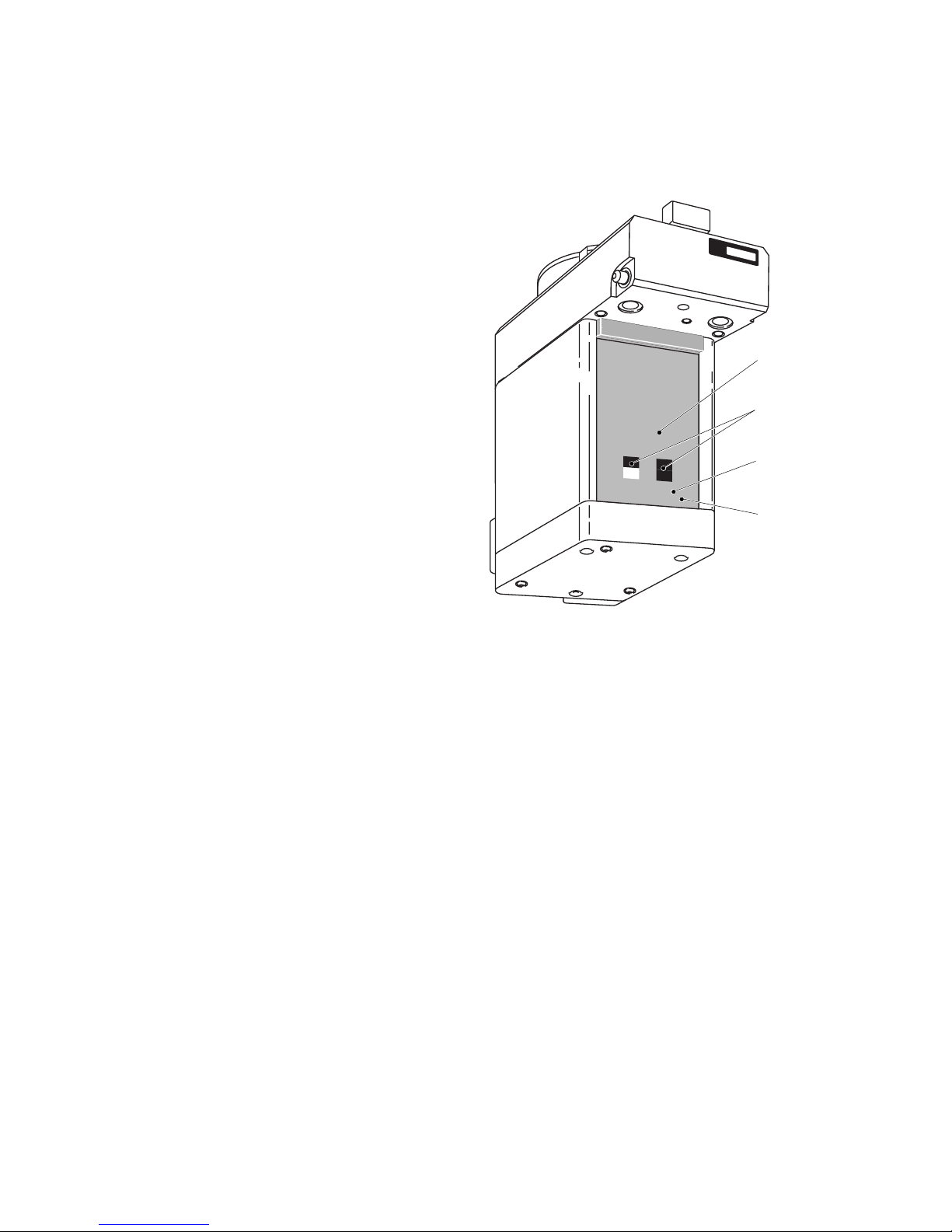
3.4 Vaporizer Identification Label
A vaporizer identification label is affixed
to the back panel of the vaporizer as
illustrated on Fig. 1.
An anaesthesia system fitted with a
vaporizer identification unit uses this label
to identify the vaporizer type.
Do not affix any additional labels or
markings to the back panel, they may
adversely affect the operation of the
vaporizer identification unit.
Fig. 1 Vaporizer Identification Label
4.0 Operating Instructions
4.1 General
The vaporizer is designed to be used on Selectatec Series Mounted Manifolds. The vaporizer can be
installed on other Selectatec Manifolds but the interlock system is designed to function on Selectatec
Series Mounted Manifolds only.
Mounting a Tec 5 vaporizer on a Selectatec 7 Compatibility Block is not recommended.
wWarning: It is a requirement of European Standard prEN 740 - Anaesthetic Workstations And Their
Modules, that the gas monitoring device referred to at 3.1 of this manual is in operating condition,
by being enabled and functioning , prior to use of the vaporizer.
wWarning: Handle the vaporizer with care at all times. Do not lift or support the vaporizer by holding
the control dial.
wWarning: Before mounting a vaporizer on to the manifold ensure that only one 'O' ring is fitted to
each manifold port valve. Ensure that each 'O' ring is intact and that there is no foreign matter
around the mating surfaces. A damaged 'O' ring and/or foreign matter around the mating surfaces
can cause leaks.
wWarning: Do not use a vaporizer if the liquid level decreases to below the minimum level.
wWarning: Before using a vaporizer allow it to attain the ambient temperature of the location in
which it is to be used.
IDENTIFICATION
CODE
AGENT NAME
VAPORIZER
NAME TEC 5
VAPORIZER
IDENTIFICATION
LABEL
AA.13.051

Tec 5 Vaporizer Page 5
O & M Manual Part No. 1105-0100-000 August 1999
123
PUSH DOWN
TO FULL EXTENT
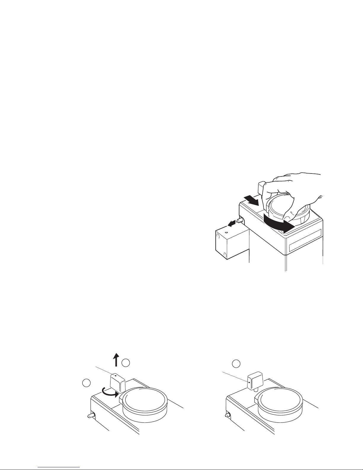
4.2 Vaporizer Mounting Procedure
1. Remove the red coloured dust caps fitted to the vaporizer interlock block ports, illustrated on Fig. 2.
2. Check that each port valve 'O' ring is intact and not damaged. Renew each 'O' ring if necessary.
3. Make sure that the vaporizer control dial is in the OFF position.
4. Make sure that the vaporizer locking lever is at the unlocked position, that is, in the up position.
Fig. 2 Vaporizer Mounting Procedure
5. Carefully lower the vaporizer on to the manifold so that the vaporizer interlock block covers the two
manifold port valves with the interlock block ports correctly engaged with the manifold port valves.
wCaution: Push the locking lever down to the full extent of its travel before attempting to turn it. The
mechanism may be damaged if an attempt is made to turn the lever before it is at the full extent of
its vertical travel.
6. Press down the locking lever
1to the full extent of its travel and then turn it clockwise
2to the
locked position
3to lock the vaporizer on to the manifold as illustrated on Fig. 3.
REMOVE DUST CAPS
FROM INTERLOCK BLOCK
PORTS
CHECK INTERLOCK BLOCK
PORTS ENGAGE CORRECTLY
WITH MANIFOLD PORT VALVES
CHECK LOCKING LEVER
IS UNLOCKED (UP)
LOCKING
LEVER
DIAL
RELEASE
LOCKED
TURN
LOCKING
LEVER
DIAL
RELEASE
CHECK DIAL IS AT OFF
CHECK EACH MANIFOLD
PORT VALVE 'O' RING. FIT
NEW 'O' RING(S) IF
NECESSARY
Fig. 3 Locking The Vaporizer On To A Manifold
AA.13.052
AA.13.053
Page 6 Tec 5 Vaporizer
August 1999 O & M Manual Part No. 1105-0100-000
4.3 Checking For Correct Mounting Of The Vaporizer
wWarning: To help to ensure correct operation, do not use a vaporizer which is visibly out of line on the
manifold or which can be lifted off the manifold when the locking lever is in the locked position.
1. If more than one vaporizer is fitted, visually check to make sure that the tops of vaporizers are square
to the manifold. If a vaporizer is visibly out of line, remove it from the manifold and attempt to mount it
correctly. Do not use a vaporizer which cannot be mounted correctly.
2. When the vaporizers appear to be level and their locking levers are in the locked position, attempt to lift
each vaporizer from the manifold.
3. If a vaporizer can be lifted OFF the manifold, remove it from the manifold and attempt to mount it
correctly. Do not use a vaporizer which cannot be mounted correctly.
4. Make sure only one vaporizer at a time can be turned ON, thus checking that the interlock rods are in
alignment.
5. Check the anaesthesia system for leaks in accordance with the relevant O&M Manual with the vaporizer
dial turned to 0% and then repeat the check with the vaporizer dial turned OFF.
4.4 Turning ON The Vaporizer
Note: Do not attempt to turn the dial if the vaporizer is
not properly locked on to the manifold.
1. Pull in the dial release illustrated on Fig. 4 and
rotate the dial counter-clockwise. Note that it is
not possible to turn ON the vaporizer if an
adjacent Tec 4, Tec 5 or Tec 6 vaporizer is turned
ON.
2. The vaporizer should not be used between OFF
and the first graduation mark. To avoid inadvertent
delivery of small concentrations the control dial
should be turned OFF when the vaporizer is not in
use. Fig. 4 Turning ON The Vaporizer
4.5 Vaporizer Removal
1. Rotate the dial clockwise to turn OFF the vaporizer. If it is not completely turned to the OFF position it
cannot be released from the manifold.
2. Referring to Fig. 5, unlock the vaporizer from the manifold by turning the locking lever
1counter-
clockwise to the unlocked position. Release the locking lever
2, check that the locking lever springs
up to the unlocked condition
3and then carefully lift the vaporizer straight up and off the manifold.
LOCKING
LEVER
UNLOCKED
LOCKING
LEVER
TURN
RELEASE
1
23
Fig. 5 Unlocking The Vaporizer From A Manifold
AA.13.053
AA.13.054
Tec 5 Vaporizer Page 7
O & M Manual Part No. 1105-0100-000 August 1999
4.6 Filling And Draining
4.6.1 General
wWarning: Do not fill the vaporizer with any agent other than the agent specified on the front label.
The vaporizer is designed for that agent only. Filling the vaporizer with any agent other than that
specified can prove to be dangerous to a patient.
wWarning: Do not fill the vaporizer unless the control dial is in the OFF position.
wWarning: Do not turn the dial ON during filling or attempt to fill beyond the ¥mark.
wWarning: Do not drain the agent into any container other than a properly marked drug container.
wWarning: Ensure that the filler cap is tightened prior to use.
Periodically check the agent level. The vaporizer should be refilled at appropriate intervals. The
vaporizer is designed to function according to specification as long as there is agent visible above
the mark.
The vaporizer must be filled and used in an upright position. Small deviations from the upright position
do not affect either the output or the safety of the vaporizer, but because the agent depth is shallow in
relation to the diameter of the vaporizing chamber, more frequent checks of the agent level should be
performed to avoid a misleading impression of the amount of agent in the vaporizer when small
deviations from the upright position occur.
At intervals, ideally not exceeding two weeks, the vaporizer should be drained into the correct drug
bottle when the agent is low. This helps to preserve the drug purity by removing oxidized impurities,
accumulated contaminants and stabilisers. Discard the agent in a manner consistent with local policies
and guidelines. Less frequent intervals may be used when the anaesthetic agent does not contain
additives or stabilising agents.
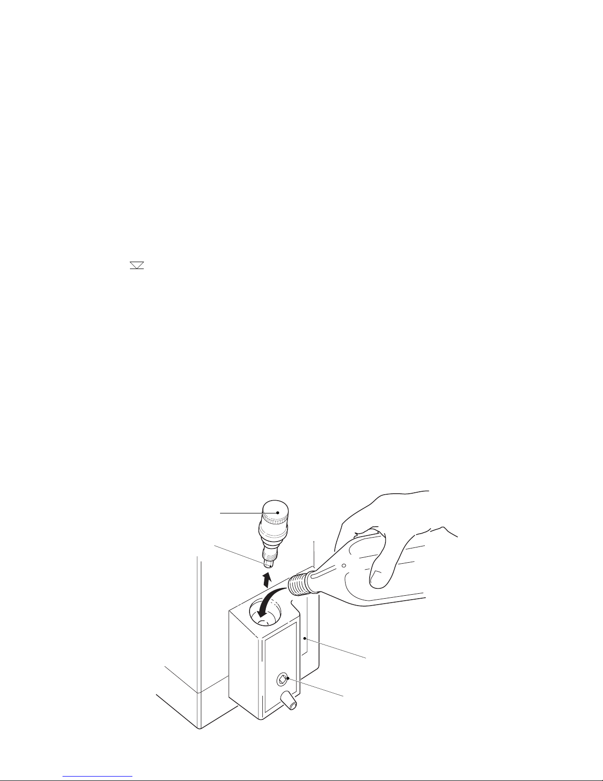
4.6.2 Filling A Vaporizer Which Incorporates A Screw Cap Filler
wWarning: Before filling a vaporizer fitted with a screw cap filler, turn the cap slowly to allow any
pressure to vent slowly.
1. Turn the vaporizer dial clockwise to the OFF position.
Fig. 6 Filling A Vaporizer Which Incorporates A Screw Cap Filler
FILLER CAP
HEXAGON
SIGHT GLASS
DRAIN PLUG
AA.13.024
Page 8 Tec 5 Vaporizer
August 1999 O & M Manual Part No. 1105-0100-000
2. Remove the filler cap by turning it counter-clockwise. Ensure that the drain plug is closed by
tightening it with the hexagonal end of the filler cap.
3. Verify that the anaesthetic agent is the same as that specified on the vaporizer front label. Observe
the agent level through the sight glass indicator on the side of the filler body and pour the agent
slowly into the filling port, as illustrated on Fig. 6, until the level reaches the¥mark. The level may
decrease slightly as the wicks absorb the agent.
4. Replace the filler cap and tighten it to minimise any possibility of leaks.
4.6.3 Draining A Vaporizer Which Incorporates A Screw Cap Filler
wCaution: Do not allow a bottle to become completely full during draining procedures.
The vaporizer must only be drained into a properly marked container, as follows:
1. Remove the filler cap and insert the hexagonal end of the cap into the drain plug situated below the
filling port on the filler body as illustrated on Fig. 7.
2. Position a properly marked container under the drain spout.
3. Unscrew but do not remove the drain plug to allow the vaporizer contents to pour from the drain
spout into the container.
4. After draining is complete, tighten the drain plug to minimise any possibility of leaks.
5. Replace the filler cap and tighten it to minimise any possibility of leaks.
FILLING PORT
DRAIN SPOUT
CONTAINER
FILLER CAP
DRAIN PLUG
HEXAGONAL
END
Fig. 7 Draining A Vaporizer Which Incorporates A Screw Cap Filler
AA.13.028

Tec 5 Vaporizer Page 9
O & M Manual Part No. 1105-0100-000 August 1999
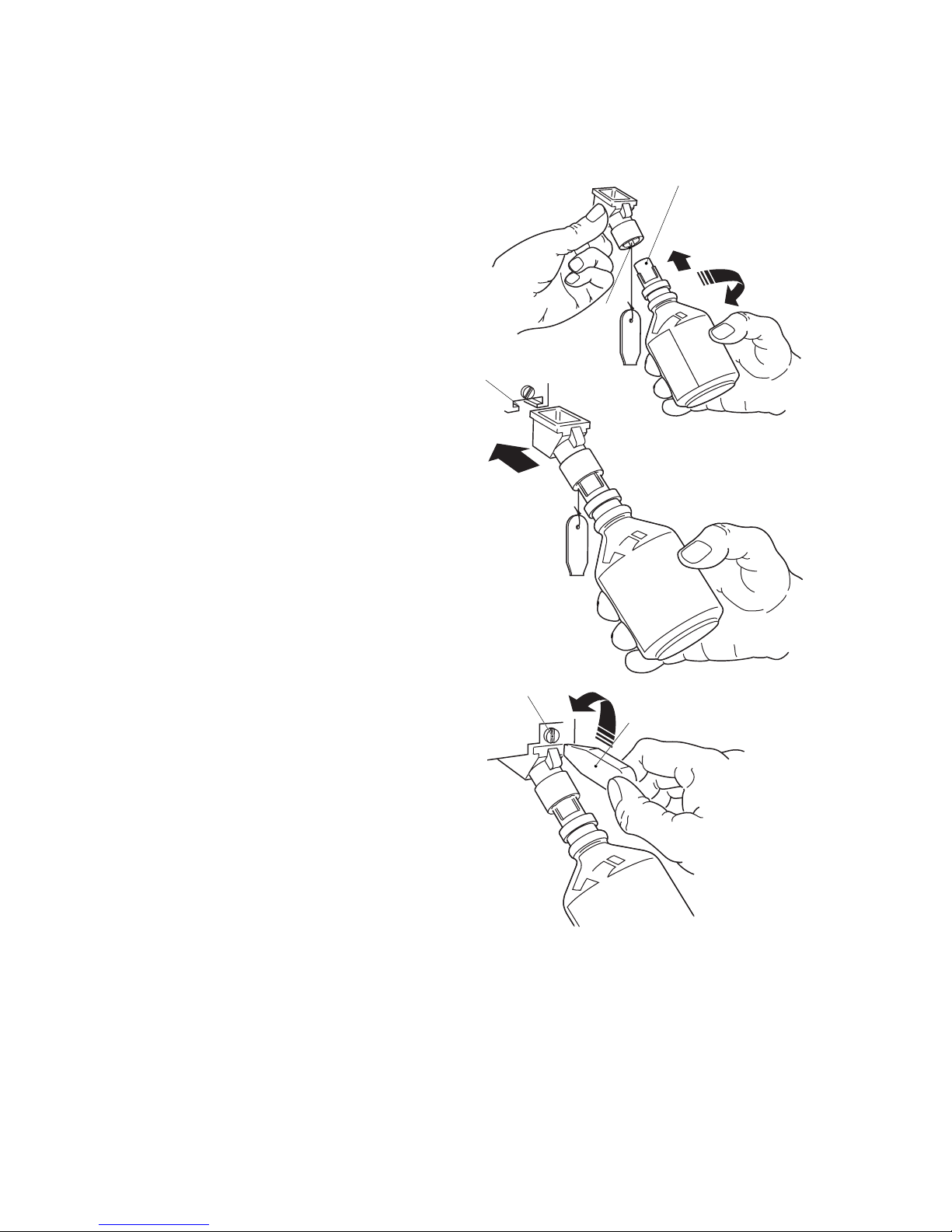
4.6.4 Filling A Vaporizer Which Incorporates A Keyed Filler
wCaution: Always hold the bottle below the level of the end of the bottle adaptor and also below the
level of the filler port until the adaptor is clamped into position.
wCaution: If it is suspected that there is liquid in the adaptor air tube, remove the bottle adaptor from
the bottle and carefully shake the adaptor two or three times to clear the tube.
The filling system consists of three elements, the bottle collar, the bottle adaptor and the filling and
draining unit fitted to the vaporizer. The vaporizer must only be filled using the correct agent specific
filling system, as follows:
1. Screw the agent specific bottle adaptor firmly on to the bottle.
2. Ensuring that the bottle (1) is held below the level of the end of the bottle adaptor and below the
level of the filler port, insert the end of the bottle adaptor into the filler port (2) as illustrated on
Fig. 8.
3. Tighten the locking clamp by pulling the locking clamp lever forward and downward (3) until the
bottle adaptor is clamped.
wCaution: When it is set correctly, the clamp secures the bottle adaptor without using the full travel
of the locking lever. The lever must not be forced to its lowest limit of travel.
4. Raise the bottle above the level of the filler port (4) and then open the filler port valve by pulling the
port valve lever forward (5) to its full extent.
3
2
6
4
5
1
021AT5 OM
Fig. 8 Filling A Vaporizer Which Incorporates A Keyed Filler
AGENT SPECIFIC
BOTTLE COLLAR
BOTTLE
LOCKING
CLAMP
LEVER
PORT
VALVE
LEVER
AGENT SPECIFIC
BOTTLE COLLAR
LOCKING
CLAMP
LEVER
AGENT SPECIFIC
BOTTLE ADAPTOR
AA.13.046
AA.13.045

Page 10 Tec 5 Vaporizer
August 1999 O & M Manual Part No. 1105-0100-000
Note: The vaporizer normally fills in less than one minute. If the vaporizer is dry the level decreases
slightly as the wick absorbs the agent.
5. When the vaporizer is full, return the port valve lever (5) to the closed condition to close the valve.
6. Lower the bottle to below the level of the filler port (6) and allow any agent in the tube to drain
back into the bottle.
7. Release the locking clamp lever, return it to the up position and then remove the bottle adaptor
from the filler port.
4.6.5 Draining Vaporizer Which Incorporates A Keyed Filler
wCaution: Do not allow a bottle to become completely full during draining procedures.
The vaporizer must only be drained into a properly marked container, as follows:
1. Position the bottle below the level of the filler port and insert the end of the bottle adaptor into the
filler port (1) as illustrated on Fig. 9.
2. Tighten the locking clamp by pulling the lever forward and downward (2) until the adaptor is
clamped.
3. Open the filler port valve by pulling the lever forward to its full extent (3).
4. Hold the bottle below the level of the filler port to allow the vaporizer contents to flow into the
bottle (4).
5. When the vaporizer is drained, close the port valve.
6. Release the locking clamp and return it to the up position.
7. Remove the bottle adaptor from the port.
2
1
4
3
022AT5 OM
Fig. 9 Draining A Vaporizer Which Incorporates A Keyed Filler
LOCKING
CLAMP
LEVER
AGENT SPECIFIC
BOTTLE COLLAR
FILLER
PORT
VALVE
LEVER
AGENT SPECIFIC
BOTTLE ADAPTOR
LOCKING
CLAMP
LEVER
AA.13.027
AA.13.026
Tec 5 Vaporizer Page 11
O & M Manual Part No. 1105-0100-000 August 1999
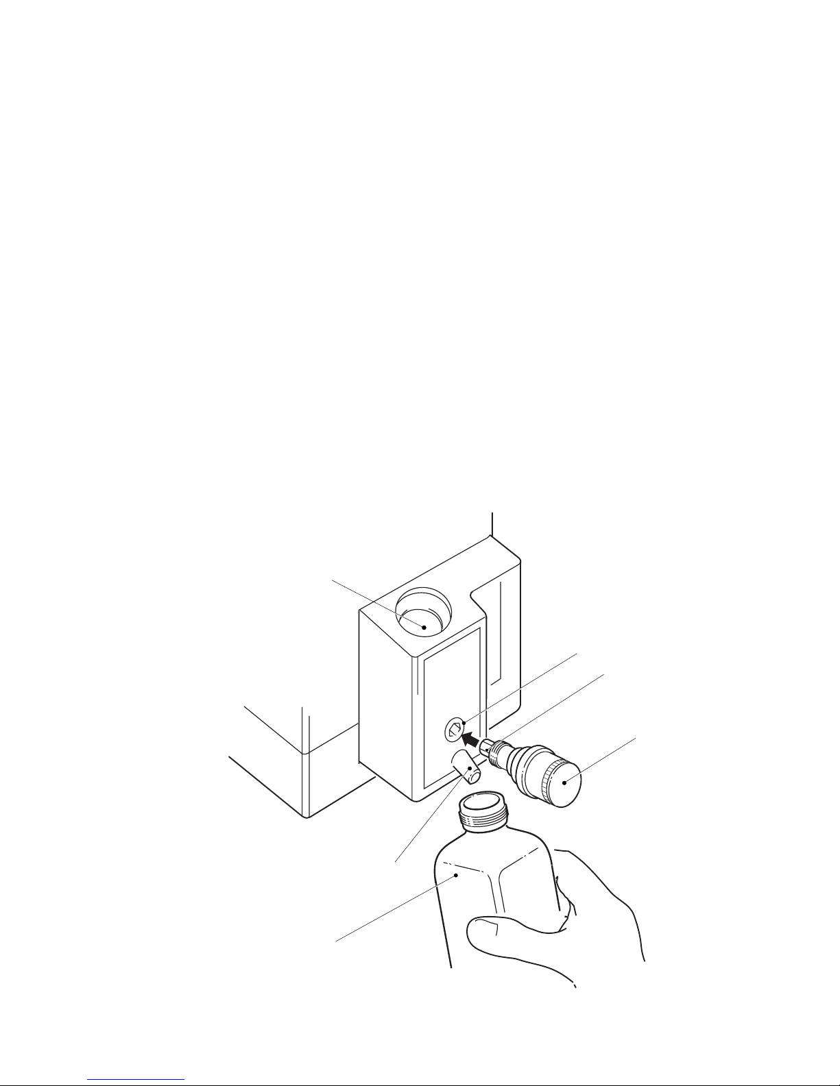
4.6.6 Filling A Vaporizer Which Incorporates A Quik-Fil™ Filler
wWarning: Ensure that the drain plug screw (1), located on the lower front of the vaporizer, is
correctly tightened to prevent loss of liquid agent.
1. Remove the protective cap from the anaesthetic agent bottle filler, checking that the bottle and filler
mechanism are not damaged.
2. Remove the filler cap (2) and insert the bottle nozzle into the filler block. Rotate the bottle to align
the bottle filler nozzle keys (3) with the index slots (4) in the filler block as illustrated on Fig. 10.
3. Press the agent bottle fully into the vaporizer filler block. Allow the liquid to flow into the vaporizer
until the maximum level mark¥is reached, paying particular attention to the level in the sight
glass and the air return bubbles flowing into the bottle.
4. Release the bottle when the vaporizer is full and the continuous stream of bubbles ceases.
5. Withdraw the bottle from the vaporizer filler and replace the filler cap (2) and the cap on the agent
bottle. Ensure that the filler cap is tightened to minimise any possibility of leaks.
2
3
1
4
Fig. 10 Filling A Vaporizer Which Incorporates A Quik-Fil™ Filler
AA.13.056
Page 12 Tec 5 Vaporizer
August 1999 O & M Manual Part No. 1105-0100-000
2
1
3
5
4
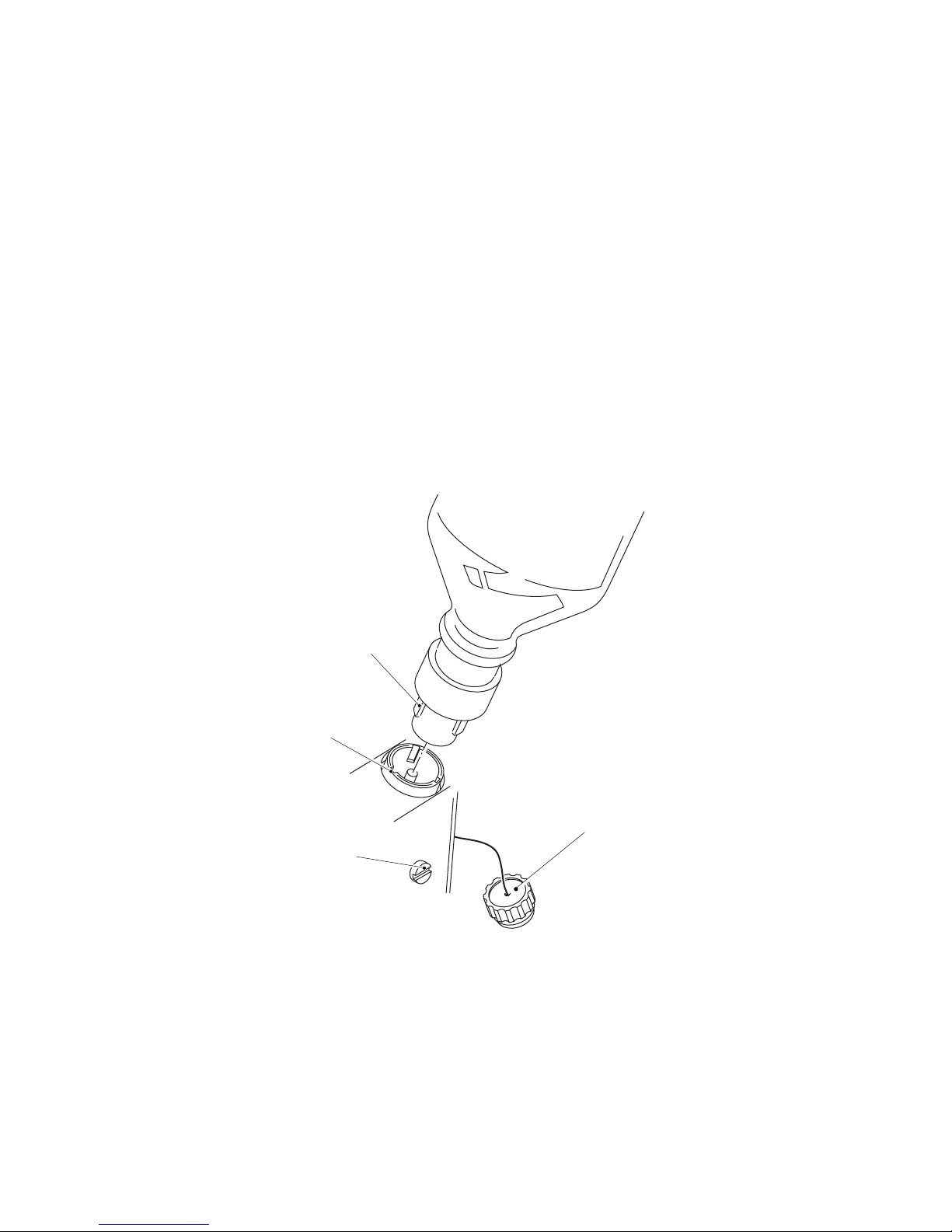
Fig. 11 Draining A Vaporizer Which Incorporates A Quik-Fil™ Filler
4.6.7 Draining A Vaporizer Which Incorporates A Quik-Fil™ Filler
wCaution: Do not allow a bottle to become completely full during draining procedures.
The vaporizer must only be drained into a properly marked container, as follows:
1. Remove the cap from the vaporizer
filler.
2. Remove the protective cap from an
empty bottle. Insert the bottle nozzle
into the drain funnel. Rotate the
bottle to align the index slots in the
drain funnel (1) with the bottle filler
nozzle keys (2) and screw the drain
funnel onto the empty bottle as
illustrated on Fig. 11.
3. Fully insert the drain funnel into the
keyed drain slot (3) in the bottom of
the vaporizer filler block.
4. Unscrew the drain plug (4) with the
key (5). Continue to drain the
vaporizer until empty.
5. After draining is complete, tighten
the drain plug to minimise the
possibility of leaks and withdraw
the drain funnel.
6. Replace the filler cap and tighten it
to minimise the possibility of leaks.
7. Unscrew the drain funnel from the
bottle and refit the protective cap.
Note: If further drain funnels are required
they should be obtained from the local
Abbott Laboratories representative.
AA.13.058 AA.13.057
AA.13.059

Tec 5 Vaporizer Page 13
O & M Manual Part No. 1105-0100-000 August 1999
5.0 Maintenance
wWarning: Do not modify, tamper with or disassemble the vaporizer because of the dangers of
damaging the unit and altering the accuracy of graduation.
Observation of the instructions previously provided, regular servicing and normal professional vigilance
is normally all that is required to maintain the vaporizer in a safe working condition.
5.1 Schedule
5.1.1 Every Two Weeks
When the agent level is low, drain the contents of the vaporizer into an appropriately marked container
and discard the agent. Less frequent intervals may be used when the anaesthetic agent does not
contain additives or stabilising agents, but the procedure must be performed at least once every year.
5.1.2 Every Three Years
Datex-Ohmeda recommends that all Tec 5 Vaporizers are serviced every three years, irrespective of
conditions of use.
The vaporizer should be serviced at an Datex-Ohmeda authorised Service Centre.
This service includes the following:
1. Complete disassembly of components.
2. Thorough cleaning.
3. Inspection for damage and wear.
4. Renewal of wicks, seals and damaged or worn components.
5. Where appropriate, replacement of discontinued parts with more up-to-date parts.
6. Lubrication where necessary.
7. Checks of delivered vapour concentrations under closely defined conditions at different
temperatures and flows with regraduation or adjustment where necessary.
5.2 Cleaning
wWarning: Do not put water or any other solvent into a vaporizer. A vaporizer should be filled with the
specified anaesthetic agent only.
wWarning: Do not immerse the vaporizer in any liquid, including water.
wWarning: Do not autoclave the vaporizer.
Clean the exterior of the vaporizer with a damp cloth.
Never allow cleaning agents to accumulate either in the filler, the gas inlet and outlet ports or around
the control dial.

Page 14 Tec 5 Vaporizer
August 1999 O & M Manual Part No. 1105-0100-000
5.3 Contamination
If the vaporizer is either filled or partly filled with an incorrect agent or any other contaminant, water for
example, proceed as follows:
1. Drain the vaporizer and discard all liquid.
2. Return the vaporizer to a Service Centre stating, if possible, the type of contaminant used.
5.4 Repairs
Repairs must only be performed by the Manufacturer's Service Representatives.

Tec 5 Vaporizer Page 15
O & M Manual Part No. 1105-0100-000 August 1999
6.0 Principle Of Operation
6.1 Interlock Mechanism
The vaporizer locking lever, illustrated on Fig. 12, is interlocked with the vaporizer percentage control dial in
such a way that the control dial release, located at the rear of the dial, cannot be actuated until the vaporizer
locking lever is in the locked position.
With the vaporizer locking lever in the locked position the dial release can be pressed in towards the dial to
operate the interlock mechanism which simultaneously actuates the following:
1. The interlock extension rods, which extend to minimise the possibility of adjacent vaporizers being
turned ON.
2. The two port valve actuating spindles, which actuate the Selectatec Manifold port valves to allow fresh
gas to flow through to the vaporizer.
3. The vaporizer percentage control dial release, which allows the dial to be turned to select the required
percentage.
Turning the control dial to OFF automatically reverses the operating sequence, which allows the dial release
to move out to lock the dial in the OFF position, closes the manifold port valves and vents the vaporizer gas
connecting ports and retracts the extension rods to allow an adjacent vaporizer to be turned ON.
Turning the locking lever to the unlocked position releases the vaporizer allowing it to be removed from the
manifold.
PERCENTAGE
CONTROL DIAL
PORT VALVE
ACTUATING
SPINDLE
SELECTATEC
SERIES
MOUNTED
MANIFOLD
CONTROL DIAL
RELEASE
VAPORIZER
LOCKING LEVER
PORT
VALVES PORT
VALVES
EXTENSION
ROD
Fig. 12 Vaporizer Interlock Mechanism
AA.13.020
Table of contents
Other Datex-Ohmeda Vaporizer manuals


