Datexel DAT 6000 SERIES User manual

DAT 6000 SERIES
ANALOG to DIGITAL
INTERFACE UNITS
for PLC
DATA ACQUISITION
- USER MANUAL -
FEATURES
- Analog Signal Acquisition on PLC digital I/O
- Models and analog inputs :
DAT6012 - 2 channels for RTD, Resistance or Pot.
- 16-bits resolution with high F.S. accuracy
- Linearization function for Tc and RTD
- PC and DIP-SWITCH configurable
- 3-ways 2000Vac galvanic isolation
- In compliance with EMC directives - CE mark
- 12.5 mm thin profile housing
- DIN rail mounting
APPLICATIONS
- Factory Automation
- Building Automation
- Agricolture Automation
- Chemical Industry Measurement
- Security system
- Machine Control

DAT 6000
2
PRELIMINARY
DAT6000
Introduction
TheDAT6000seriesisanevolutionintheconnectiontechniquesoftheanalog
signals to the PLC.
Thedevicesofthisserieperformsmanyfunctionsas:amplification,linearization,
isolation,filteringandconversionofanalogsignals,comingfromvarioussensors,
in a high resolution digital signal. The digital signal is transfered to the PLC by
abusconnected to any oneofthe controller’sdigitalinput. It is composedbya
series of 16-bit ‘words’ containing the values of the analog signals to be
measured.ThetransferisPLC controlled by a clock signal comingfromoneof
its output ports. At every clock pulse a bit of the data is transmitted.
Using few and simple instructions the PLC is even capable to acquire more
analog signal on a single digital input.
The devices are also provided of an Enable signal which, handled by the
controller, allows to " multiplexing " many devices on the same digital input.
The DAT6000 series is composed of the following devices:
Device Channels Input Type
DAT 6011 2 mV and Tc
DAT 6012 2 RTD, Res. and Pot.
DAT 6013 2 V and mA
DAT 6021 4 mV and Tc
DAT 6023 4 V or mA
DAT 6000
3
PRELIMINARY
4.7 K4.7 K
4.7 K
DC/DC
N
P
M
O
R
Q
>560 R
18..30 Vdc
+
ENABLE
DATA
CLK
GND +V
DAT 6000 PLC
+V
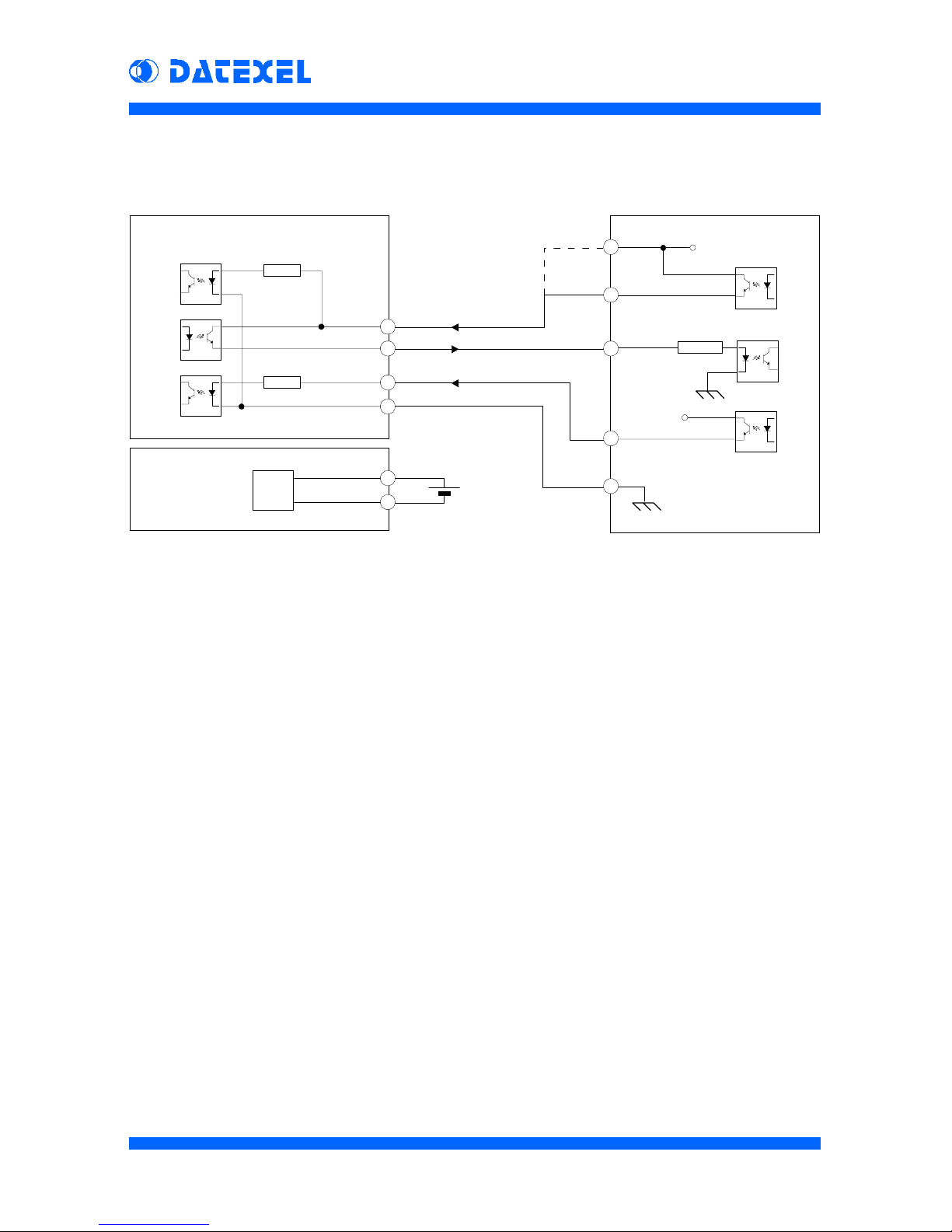
How to connect DA T6000 to PLC
TheserialinterfaceoftheDAT6000seriesdevicesisshownhereup.Inputand
output signals are optoisolated among analog input and power supply. The
DATAsignalcircuitispowereddirectlywiththeENABLEsignalvoltage.Without
the ENABLE signal, the data output is disabled. The ENABLE input
(terminalN)can beconnecteddirectlytothesupply voltage,leavingavailablea
PLC output port; in this case the data output is always enabled. Using the
ENABLEsignal,theCLKsignalcanbealwaysactive,becausewhenENABLE
signal is off, the microprocessor ignores the clock signal, stopping the data
sending; by this way, it is possible to connect many devices in multidrop
connection, using few PLC I/O ports.
The power supply of the DAT6000 is isolated from the serial interface so that
the auxiliary supply of the PLC can be used to power it.
DAT 6000
4
PRELIMINARY
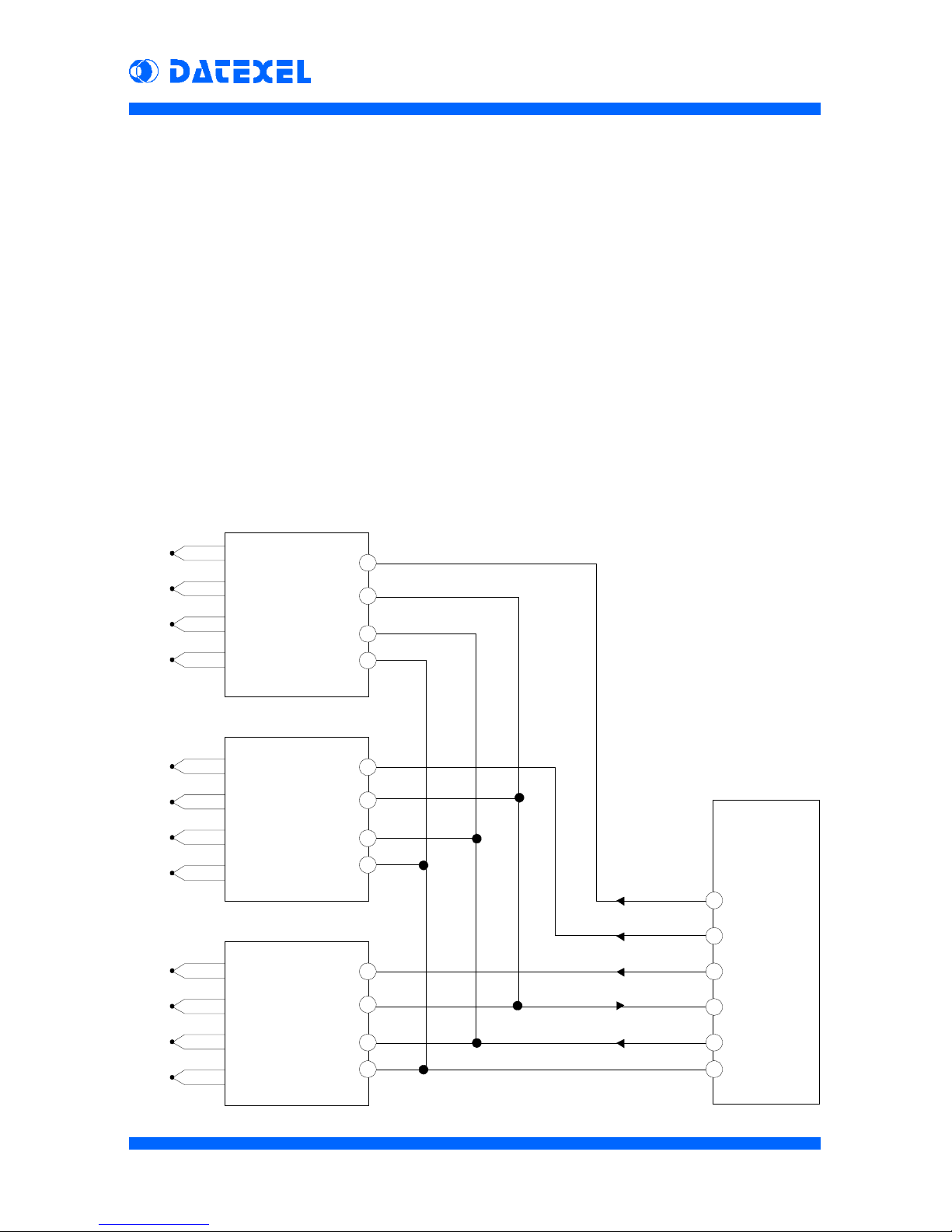
Multidrop connection
The CLK input and the DATA output of the DAT6000 devices are actives only
when the ENABLE signal is on. Consequently It is possible to connect all the
DATA signals to the same PLC digital input and all the CLK signals to the same
PLCdigitaloutput. Devices can beactivatedone by one sendingtheENABLE
signal to the selected device only.
Asshownin the figure below,using n°3 DAT6000 devices it ispossibleto read
thevalueofupto12analog sensorsusingonly4PLC digitaloutputsand1PLC
digital input. Each new device connected will use only one more PLC digital
output(ENABLE).
Changingthedevicetype,itispossibletocreatemany combinations of analog
inputs (i.e.: 4 Tc inputs on the first device, 4 mA inputs on the second device
and2Potentiometerinputsonthethirddevice),withoutto change the wiring to
thePLCandthesoftwaredatareadingprocedure.
P
M
O
ENABLE 3
DATA
CLK
GND
DAT6021
N° 1
P
M
O
P
M
O
N
N
N
ENABLE 2
ENABLE 1 Digital out
Digital out
Digital out
Digitalin
Digital out
Ground
Tc 1
Tc 2
Tc 3
Tc 4
Tc 5
Tc 6
Tc 7
Tc 8
Tc 9
Tc 10
Tc 11
Tc 12
DAT6021
N° 2
DAT6021
N° 3
PLC
Digital I/O

DAT 6000
5
PRELIMINARY
Analog Inputs connection
Tc
wiring
mV
wiring
DAT 6011
Tc
wiring
mV
wiring
DAT 6021
DAT 6000
6
PRELIMINARY
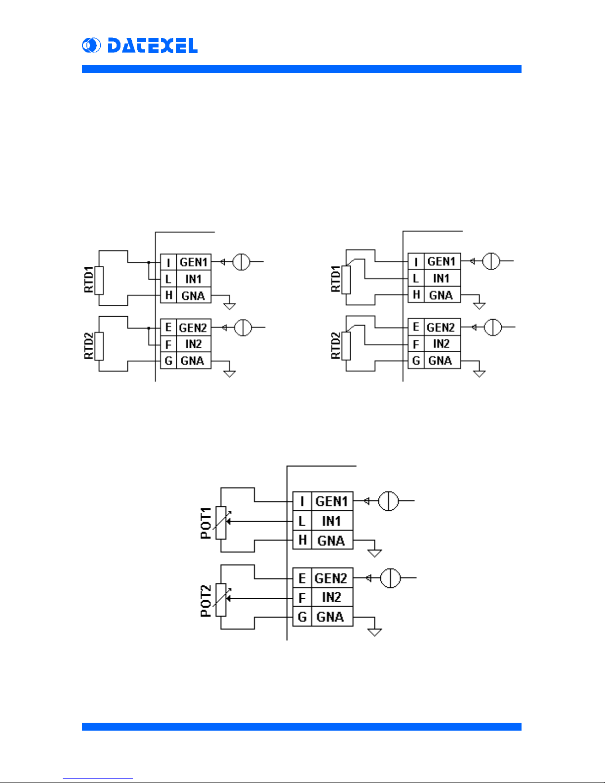
3wiresRTD/Res
wiring
2wiresRTD/Res
wiring
DAT 6012
Potentiometer
wiring
DAT 6000
7
PRELIMINARY
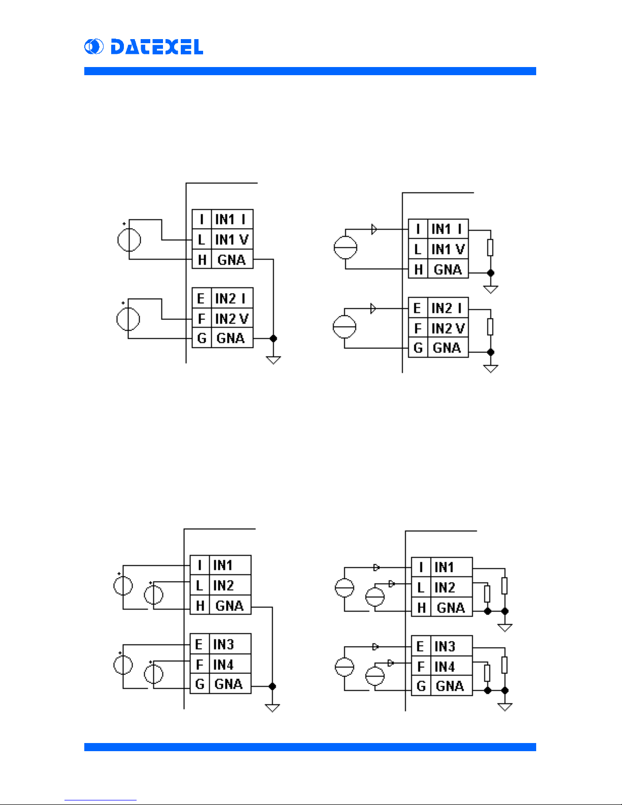
mA
wiring
V
wiring
DAT 6023
V
wiring
DAT 6013
mA
wiring
DAT 6000
8
PRELIMINARY
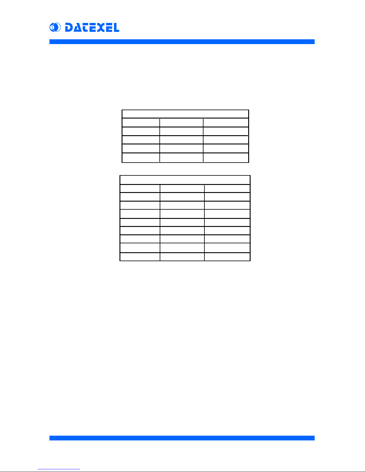
Technical Characteristics
Analog Inputs
mV
Input Min Max
50 mV -50 mV +50 mV
100 mV -100 mV +100 mV
500 mV -500 mV +500 mV
1000 mV -1000 mV +1000 mV
DAT 6011, DAT 6021
Channels: 2 ( DAT 6011 )
4 ( DAT 6021 )
InputType: ± 50 mV to ± 1V
Tc: J, K, T, E, R, S, B, N
Calibration Accuracy: ± 0.1 F.S.
Linearity: ± 0.2 % for Tc
Lead wire resistance influence: < 0.8 uV/Ohm
Input impedance: > 10 MOhm
Cold Junction Compensation: ± 0.5 °C
Thermal Drift: ± 0.005 % F.S. /°C
Sampling Rate: 10 samples/sec
Bandwidth: 4Hz
Thermocouple
Input Min Max
Tc J -210 °C +1200 °C
Tc K -210 °C +1372 °C
TcT -210 °C +400 °C
Tc E -210 °C +1000 °C
Tc R -50 °C +1767 °C
Tc S -50 °C +1767 °C
TcB +400°C +1825 °C
Tc N -210 °C +1300 °C
DAT 6000
9
PRELIMINARY
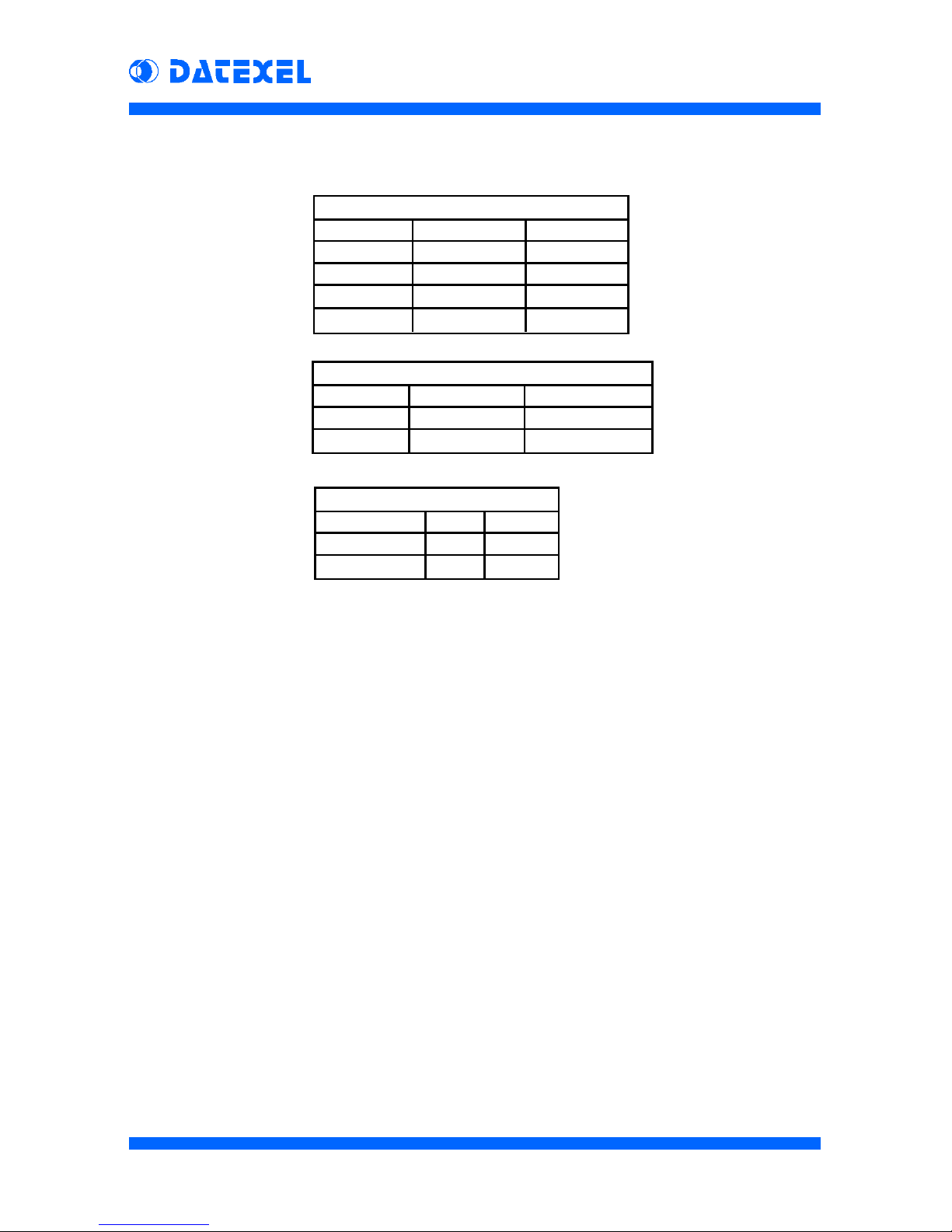
DAT 6012
RTD
Input Min Max
Pt100 -200°C +850°C
Pt1000 -200°C +200°C
Ni100 -80°C +180°C
Ni1000 -60°C +150°C
Resistance
Input Min Max
Low 0 Ohm 500 Ohm
High 0 Ohm 2000 Ohm
Potentiometer
Input Min Max
<500 Ohm 0 % 100 %
<2000 Ohm 0 % 100 %
Channels: 2
InputType: RTD (Pt100, Pt1000, Ni100, Ni1000)
Resistance and Potentiometer (up to 2KOhm)
Calibration Accuracy: ± 0.1°C for RTD; ± 0.1 Ohm for Resistance;
± 0.1 % for Potentiometer;
RTD Linearity: ± 0.2 °C
RTD Excitation Current: 0.350 mA typ.
Lead wire resistance influence: < 0.05 %/Ohm (50 Ohm max.) for 3 wires RTD
Thermal Drift: ± 0.005 % F.S. /°C for RTD
Sampling Rate: 10 samples/sec
Bandwidth: 4Hz

DAT 6000
10
PRELIMINARY
DAT 6013 - DAT 6023
Voltage
Input Min Max
10 V -10 V +10 V
Current
Input Min Max
20 mA -20 mA +20 mA
Channels: 2 ( DAT 6013 )
4 ( DAT 6023 )
InputType: ± 10V or ± 20 mA *
Calibration Accuracy: ± 0.05 %
Linearity: ± 0.1 %
Input Impedance: > 1MOhm for V ; 47 Ohm for mA
Thermal Drift: ± 0.005 % F.S. /°C
Sampling Rate: 10 samples./sec
Bandwidth: 4Hz
* For DAT 6023 the input type is not configurable.
It must be to defined at order (V or mA).
SupplyVoltage: 24 Vdc typical (30 Vdc max)
ON state voltage: > 9 Vdc
InputImpedance
(ENABLE,CLK): 4.7KOhm
MinimumOutputLoad
(DATA): 560 Ohm
Maximum Clock signal frequency:
< 500 Hz (with 1ms filter)
< 50 Hz (with 10ms filter)
DebounceFilter: settable to 1ms or 10 ms
RiseTime: <0.2 ms
DIGITAL INTERFACE
DAT 6000
11
PRELIMINARY
SUPPLY
SupplyVoltage: 18 to 30 Vdc
SupplyCurrent: 35 mA @ 24 Vdc
Polarityreversalprotection: 60Vdc
Temperature and Humidity
OperatingTemperature: -10 ÷ +60 °C
StorageTemperature: -40 ÷ +85 °C
RelativeHumidity(notcondensing): 0 ÷ 90 %
EMC
Emission EN50081-2
Immunity EN50082-2
RF Immunity tested @ 10 V/m up to 1000 Mhz
Housing
Material Selfestinguishing Plastic
Mounting DINRail
Weight 50 g. approx.
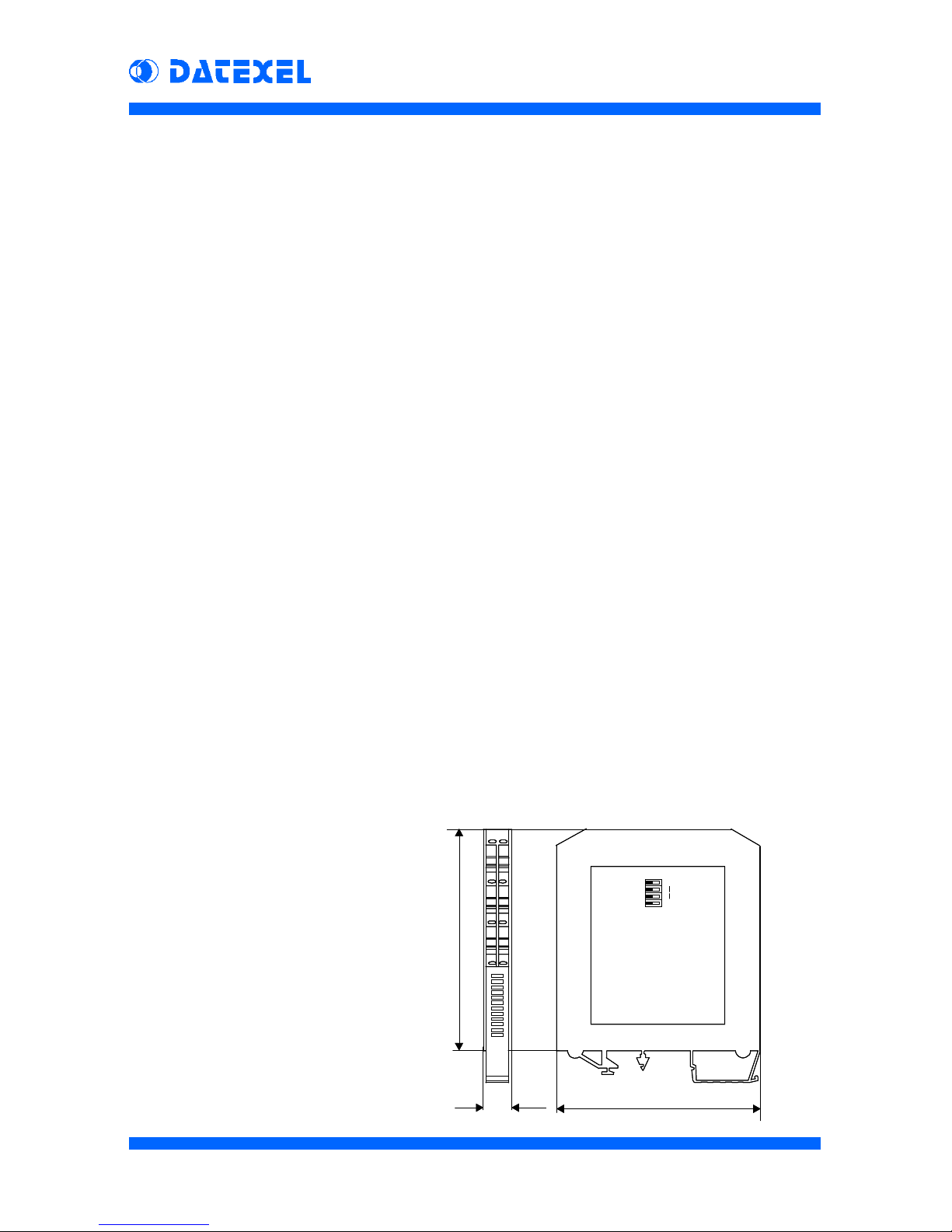
Dimensions
(W x H x T) in mm: 90 X 98 X 12.5
Mechanical
Dimensions (mm)
12.5 90
98
EF
GH
IL
SW1
SW4

DAT 6000
12
PRELIMINARY
How to Program the module
The input type is in-field configurable by means of the dip-switches. The input
type configuration is made by SW1..SW3 dip-switches which can be used to
setup to8differentinput types.Thestandardcorrespondance betweenthedip-
switchsettingandtherelative input type is shown in thetablesbelow. It can be
modifiedusingthe ‘PRO6000’softwareandthePRODAT-03interface.
By this way, it is possible to reconfigure the module for a wide range of input
signal types at any time.
Also the CLK signal’s digital filter can be set to 1 ms or 10 ms (half-period
duration) by a dip-switch (SW4). The digital filter eliminates all the signal
variations shorter than the specified time, avoiding undesired command
simulations.
Hereafterthestandardtablesofthevariousmodulesareshown:
DAT6012 and DAT6013 modules, having a limited number of possible input
types, are availables with a fixed table. Whereas DAT6011 and DAT6021 are
available as in Tab.A or in Tab.B, indicating the choice at the order, or in any
desired configuration using the software, as previously mentioned. DAT6023
module is not configurable; consequently the input type (V or mA) must be
definedattheorderphase.
SW1 SW2 SW3 Input Input
Tab.A Tab.B
0 0 0 Tc J 50 mV
0 0 1 Tc K 100 mV
0 1 0 TcT 500 mV
0 1 1 Tc E 1000 mV
1 0 0TcR---
1 0 1TcS---
1 1 0TcB---
1 1 1TcN---
SW1 SW2 SW3 Input
0 0 0 Res. L
0 0 1 Res. H
0 1 0 Pt100
0 1 1 Ni100
1 0 0 Pt1000
1 0 1 Ni1000
1 1 0 Pot. L
1 1 1 Pot. H
DAT6011-DAT6021 DAT6012
DAT6013
SW1 SW2 SW3 Input
x x 0 10 V
x x 1 20 mA

DAT 6000
13
PRELIMINARY
How to create an Input Table
Allthepossible input types ofthemodule are listed inamain table (Tab.1).Itis
possibleto associate up to 8 of this input types to eachone of the 8 dip-switch
combinations,followingtheorderofTab.1 andcomplingtoeverychoosedtype
the first free dip-switch combination. By this way the ‘dip-switch to input type’
correspondencetableiscreated (Tab.2).
The example is referred to DAT6011 module and shows how to associate the
heightdip-switchcombinationstothree‘mV’inputs(50mV/100mV / 1000mV)
andfive ‘Tc’ inputs (Tc J/K/R/S/N):
In any case, it is sufficient to set the desired data in the “PRO6000” program,
andthetablewillbeautomaticallycreated.Moreoverthesoftwarewillprovideto
program the module in the correct way.
Tab.2
SW1 SW2 SW3 Input
0 0 0 50 mV
0 0 1 Tc J
0 1 0 Tc K
0 1 1 Tc R
1 0 0 Tc S
1 0 1 Tc N
1 1 0 100 mV
1 1 1 1000 mV
Tab.1
Pos. Input
0 50 mV
1 Tc J
2 Tc K
3 TcT
4 Tc E
5 Tc R
6 Tc S
7 Tc B
8 Tc N
9 --
10 --
11 --
12 --
13 100 mV
14 500 mV
15 1000 mV
50 mV
Tc J
Tc K
Tc R
Tc S
Tc N
100 mV
1000 mV
DAT 6000
14
PRELIMINARY
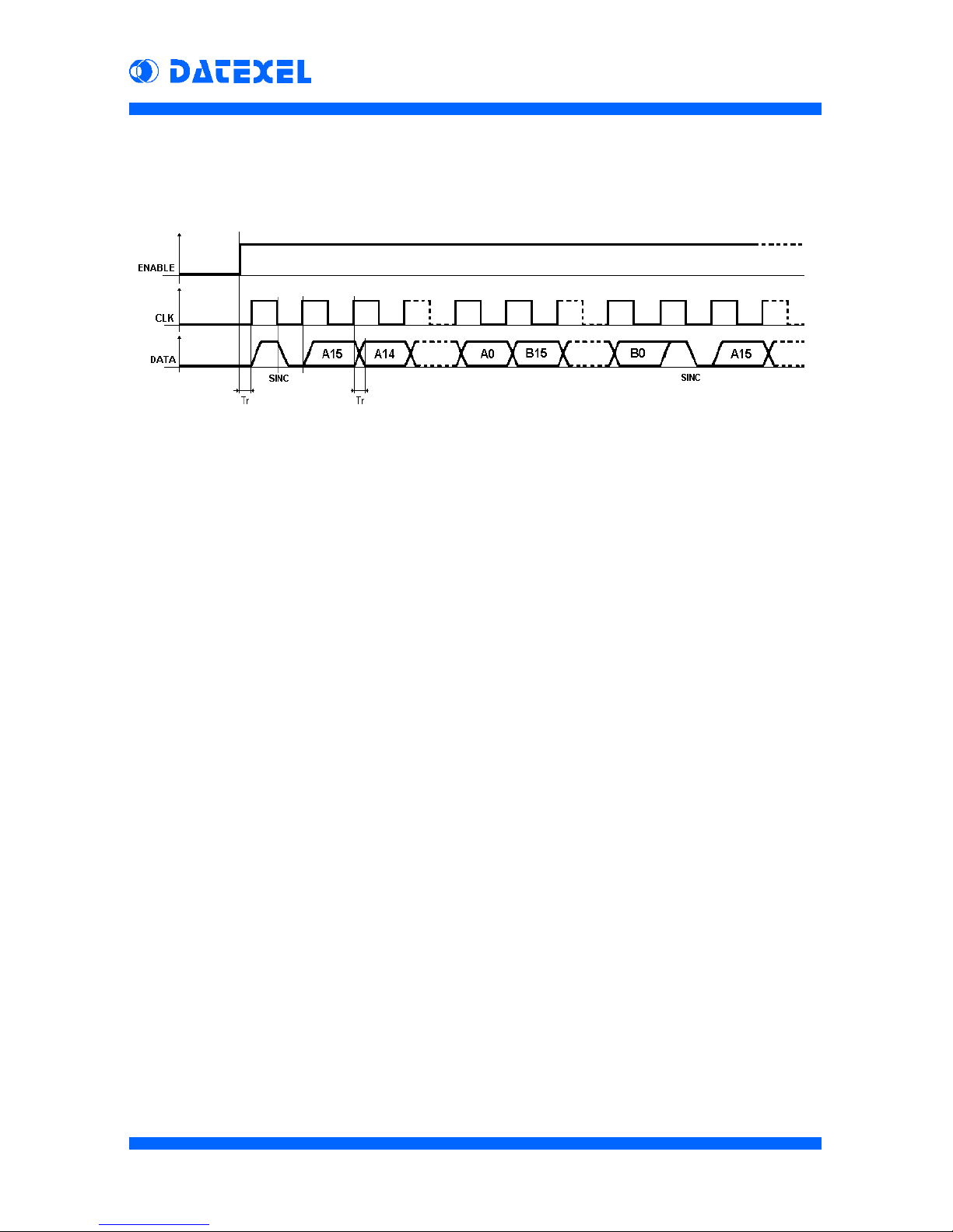
Data Reading
The data transfer is made sending an enabling signal (ENABLE) and a clock
signal (CLK). If the ENABLE signal is high, a bit composing the reading is
providedon the output (DATA) at every clock pulse.
Everyreadingcycleiscomposedof1synchronismbitfollowed of a 16 bit word
for each analog input signal (channel). So that any reading is composed of 33
bitsfor 2-channels and 65 bits for 4-channels.
The synchronism bit indicates that the next bit is the most significant bit of the
first channel value (A15); the following remaining bits of this value will be
transmitteddowntotheleast significant bit (A0). This bit willbefollowedbythe
mostsignificantbitofthesecondchannelvalue(B15),downtotheleastsignificant
bit (B0). After the last bit, a new synchronism bit will be transmitted.
The value to be transmitted will be updated during the transmission of the
synchronism bit. During the reading cycle, the ENABLE signal must stay at
logiclevelHI.
The first bit after the ENABLE signal rise front will be a synchronism bit.
The synchronism bit level is high when the CLK signal is high and is low when
theCLKsignalislow. Differently, each data bit isupdatedontheCLKrise front
and mantains its level until the next CLK rise front.
At any moment it is possible to send a rise front on the ENABLE signal to
restart the reading cycle (by the synchronism bit).
The‘DebounceFilter’eliminatesallthesignalvariationsshorterthanthespecified
time,avoidingundesiredcommandsimulations.

DAT 6000
15
PRELIMINARY
Start condition:
ENABLE low and CLK low, then DATA is automatically low.
Initialization:
1 - ENABLE High
2 - Wait for Tr
Synchronism:
3 - CLK High
4 - Wait for Tr
5 - Read DATA
6 - DATA logic level must be 1 otherwise go to point 3 *
7 - CLK Low
8 - Wait for Tr
9 - Read DATA
10 - DATA logic level must be 0 otherwise go to point 3 *
Bit reading:
11 - CLK High
12 - Wait for Tr
13 - Read DATA
14 - CLK Low
15 - Wait for Tr
16 - Read DATA
17 - DATA logic level read on point 13 and on point 16 must be the same,
otherwise go to point 3 *
18 - Save the DATA logic level as bit in the reading register
Channel reading:
19 - Repeat points 11 to 18 for all the 16 bits of the measure, writing the bits
in the reading register from the most significant one down to the least
significant one
20 - Repeat points 11 to 19 for all the channels to read
21 - After the 16° bit of the last channel (2nd or 4th) return to point 3
To abort the reading without to read all the channels:
22 - Be sure the CLK is Low
23 - ENABLE Low
24 - Wait for Tr
25 - Go to point 1
* Synchronization is failed, then disregard the last reading. The data acquisition will
be delayed until the next synchronism bit will be recognized. It is advisable to abort
the reading procedure going to point 22.
NOTE: ‘Tr’ is the Debounce Filter time setting (1ms or 10 ms)
Thecorrect proceduretoacquirethemeasuresbythemodulecanbedescribed
asfollowing:
How to write the PLC’s instructions

DAT 6000
16
PRELIMINARY
EXAMPLE n°1 : 2 or 4 channels reading
The procedure is fast and with few instructions because there are not
synchronismcontrols.However,if thesynchronismis lost (i.e. foranoise), the
readingwillbewrong.Toavoidthat,itisadvisabletousetheENABLEsignalto
synchronize the procedure at the reading start.
The following two examples, each one toghether with its flow-graph, illustrate
theprocedure to be followedfor writing the PLC’sinstructions.
START
ENABLE HIGH
DELAY
n = n - 1 n = 0 ?
READ BIT
REGISTER [n] = y
CHANNAEL (a) =
REGISTER
n = 15
a = a + 1
a = 2 ?
(NOTE 1)
DELAY
CLK LOW
DELAY
CLK HIGH
y = DATA
READ BIT
a = 0
end of channels reading
YES
NO
YESNO
read next channel
end of channel reading
read next bit
read input bit
READ BIT
The first bit is the
most significant
ENABLE LOW
DELAY
NOTE 1 : to be modified following the number of channels to be read ( write " a = 4 ? " for the 4 channels reading )
NOTE 2 : follow the (A) option to reset the device or for not reading the unused channels
A
NOTE 2
Definitions:
ENABLE, CLK and DATA = interface signals
SYNC = synchronism bit
REGISTER = data reading buffer
n = a bit of REGISTER buffer (0..15)
CHANNEL = digital channel measurement value
a = channel number (1,2,3 or 4)
x, y = bits
DELAY = delay function (ms). The delay time must be
higher than the setting of the digital filter

DAT 6000
17
PRELIMINARY
EXAMPLE n°2 : 2 or 4 channels with synchronism control
The continuous control of the received bit allow a sure synchronization of the
procedure.Whenthe synchronismislost,thenextreading willbesurelycorrect
because it will starts only when a synchronism bit will be recognized. It is not
necessary to use the ENABLE signal.
START
ENABLE HIGH
DELAY
n = n - 1 n = 0 ?
READ BIT
SYNC
?
REGISTER [n] = y
CHANNEL (a) =
REGISTER
n = 15
a = a + 1
Definitions:
ENABLE, CLK and DATA = interface si
g
nals
SYNC = synchronism bit
REGISTER = data readin
g
buffer
n = a bit of REGISTER buffer (0..15)
CHANNEL = di
g
ital channel measurement value
a = channel number (1,2,3 or 4)
x, y = bits
DELAY = delay function (ms). The delay time must be
hi
g
her than the settin
g
of the di
g
ital filter
DELAY
CLK LOW
DELAY
x = DATA
y = DATA
CLK HIGH
x & y
compare
SYNC ERROR
READ BIT
a = 0
end of channels reading
YES
NO
YESNO
NO
YES
read next channel
end of channel reading
read next bit
read input bit
READ BIT
DATA
?
YES
NO
data-bit received
wrong bit received
DATA
x=1
y=0 x=0
y=1
x=y
the first bit is the
most significant
synchronism found
first channel reading
ENABLE LOW
DELAY
a = 2 ?
(NOTE 1)
NOTE 2
A
NOTE 1 : to be modified following the number of channels to be read ( write " a = 4 ? " for the 4 channels reading )
NOTE 2 : follow the (A) option to reset the device or for not reading the unused channels

DAT 6000
18
PRELIMINARY
Data Format
Themoduleacquiresthe analog signal value ofeachchannelandconvertsitin
a digital string (bit). Each analog signal is converted in a 16 bit word which is
seriallytransmittedas before described.
Then,itis possible to convertthereceived string in thecorrespondingdecimal
value, considering that each value is expressed in signed integer (the most
significantbitindicates the sign: 0=positive1=negative).
Theuserwill must insert thedecimalpoint as illustrated inthefollowing tables.
Input Binary Hex Decimal Measure
Ohm 0000 0000 0000 0001 0001 1 0.1 Ohm
100 mV 0010 0001 0011 0100 2134 8500 85.00 mV
1000 mV 1111 1111 1111 1111 FFFF -1 -0.1 mV
Tc J 1111 1000 0011 0000 F830 -2000 -200.0 °C
Examples:
Input Decimals Format
RTD (°C) 1 +850.0
Res (Ohm) 1 +2000.0
Pot (%) 1 +100.0
Input Decimals Format
+/- 50 mV 3 +50.000
+/- 100 mV 2 +100.00
+/- 250 mV 2 +250.00
+/- 1000 mV 1 +1000.0
+/- 20 mA 3 +20.000
Tc J .. Tc N 1 +1200.0

DAT 6000
19
PRELIMINARY
NOTE :

DAT6012 2 Channel RTD PLC Input
This manual suits for next models
5
Table of contents
Other Datexel Recording Equipment manuals

Popular Recording Equipment manuals by other brands


Mastervolt
Mastervolt MasterBus LIN Interface User and installation manual

Axxess
Axxess AX-FD1-SWC installation instructions

Attero Tech
Attero Tech unAIO2X2+ user manual

aci
aci TIF-401 Installation and reference guide

Basler
Basler BE3-25A instruction manual

PRACQ
PRACQ MELODIC STEP SEQUENCER Reference manual


