Datum Storage 4Post Trakslider User manual
FOR ASSEMBLY ASSISTANCE CONTACT CUSTOMER SERVICE AT 1-866-217-0330
(MONDAY THRU FRIDAY 8 AM - 5 PM EST)
4Post Trakslider Instructions
INST0083REV2WS4/16/08
PAGE 1 OF 31

7/32" Nut
Driver
7/16" Wrench
Phillips Head
Screwdriver
5/16" Drill Bit
(Required when not
using Datum shelving)
Power Drill
Rubber Mallet
Or
Plastic Tip Hammer
4' Bubble Level
NOTE
These instructions apply to Datum 4Post Shelving with 4Post
Adapter Brackets. If other brands are used, it will be necessary
to drill holes to complete installation.
Tools Required for Assembly
PAGE 2 OF 31
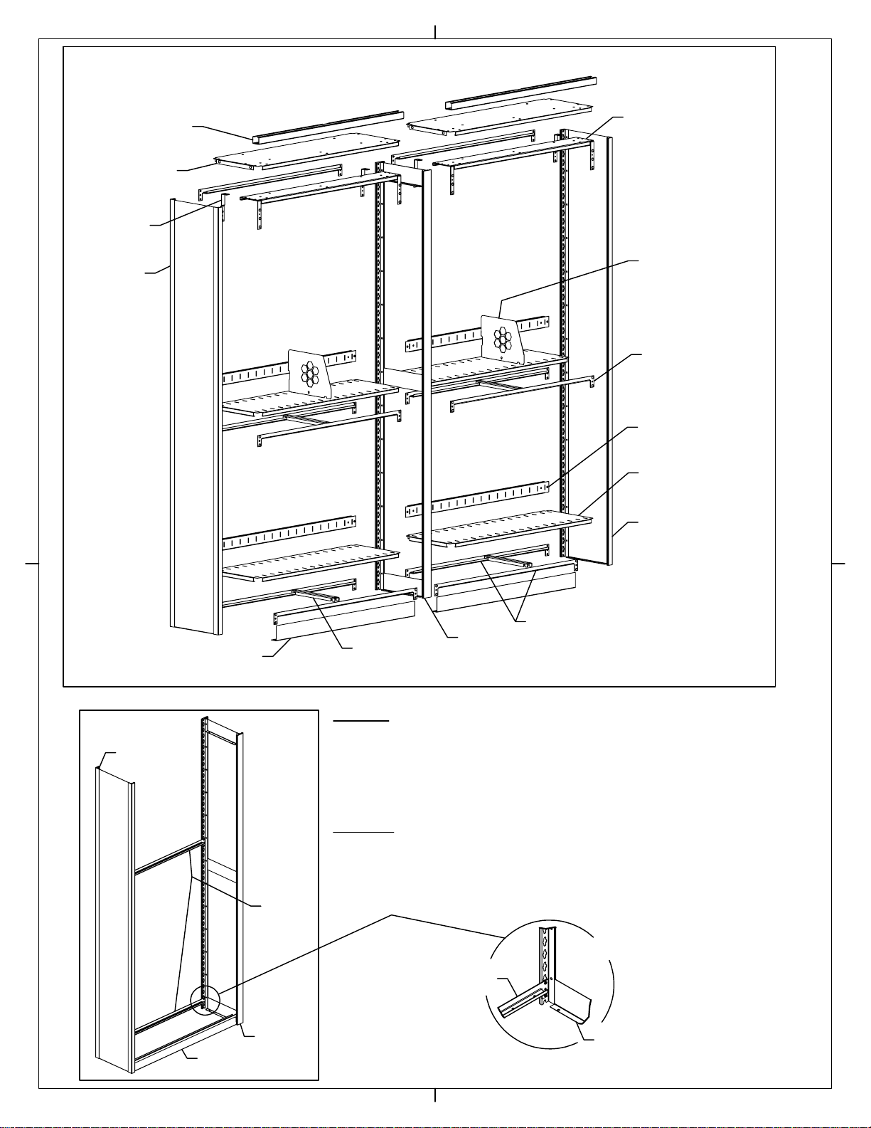
Figure A
Detail B
Step1:
Temporarily mount a standard shelf support at chest height between a closed "L"
upright on left and an open "T" upright on right to hold uprights in position (see
Figure A). Make sure that the uprights are positioned so that bent flanges are at
the bottom of the unit as shown in Detail B. Rivets of shelf support fit into keyholes
on uprights as shown in Figure A & Detail B. Use a rubber mallet or plastic tip
hammer to tap shelf support into bottom of keyholes.
Step 2:
A kick plate will only be used on the forward facing side of a single entry unit or
both sides of a double entry unit. Place kick plate against uprights then place
standard shelf support into uprights and tap in place with a rubber mallet or plastic
tip hammer to seat rivets into bottom of keyholes.
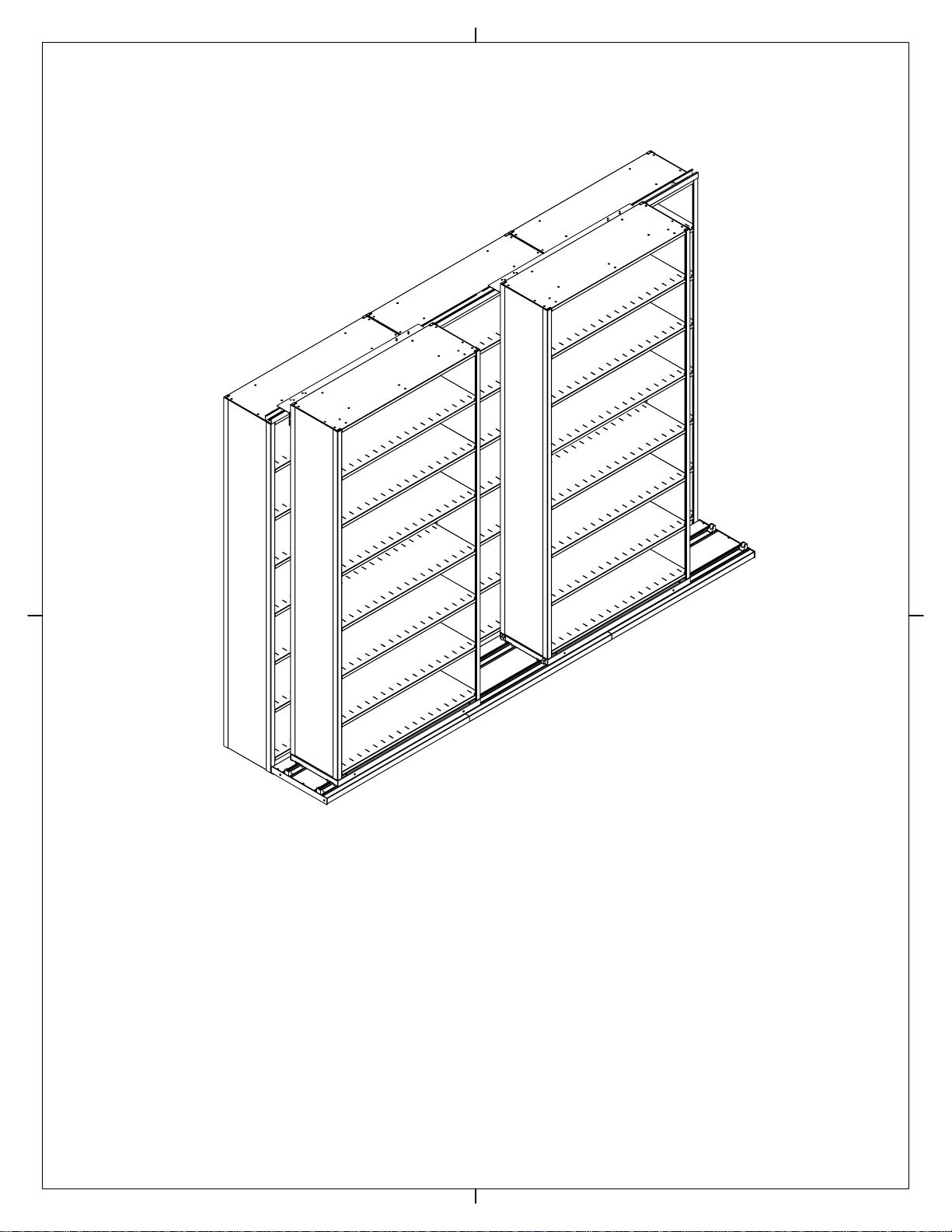
Parts Required for Typical Rear
Stationary Shelving Section
Closed 'L'
Upright
Standard
Shelf
Support
Open 'T'
Upright
Shelf
Support
Bent Flange of Upright
at bottom of unit
Top Stabilizer
Channel
Top Cover
w/Knockouts
Top Cover
Lock Bracket
Closed 'L'
Upright
Shelf
Reinforcement
Open 'T'
Upright
Standard
Shelf Support
Closed 'L'
Upright
Slotted
Shelf
Back
Stop
Standard
Shelf Support
Divider
Top Cover Front
Support Channel
PAGE 3 OF 31
Kick Plate
Kick Plate

Figure C
None
Number of
Reinforcements/Shelf
None
Two
Table 1 - Shelf Reinforcements
for Stationary Shelving
15"
12"
Depth of
Shelving
18"
Step 3:
If required (See Table 1), install shelf reinforcements
as shown in Figure C.
Step 4:
Install bottom shelf by tilting the shelf as shown if
Figure D. Shelf should then lie flat on shelf supports.
Figure D
Figure E
Step 5:
Install back stop for bottom shelf. Count up three
complete keyholes from top of shelf and place rivets
located on each end of back stop in these keyholes
(see Figure E).
Shelf
Reinforcements
Shelf
Support
Shelf
PAGE 4 OF 31
Kick Plate
Kick Plate
Bottom
Shelf
Back
Stop
Third
Keyhole

Figure F
Figure G
Step 6:
Install remainder of shelf supports, shelves, back stops, & shelf reinforcements
(if required) as previously shown, working from bottom to top. Keep in mind
your installation may be different, as shelf spacing varies from job to job (See
Figure F for typical configurations). Do not install components at the top of unit
at this time; when complete the assembled unit should look similar to Figure G.
Fourth Opening Typically
Has Posting Shelf (Letter/Legal)
11 5/16
9 13/16
Third Opening Typically
Has Posting Shelf (X-Ray) 18 9/16
15 9/16
Typical Clear Openings for
Letter/Legal Shelving Typical Clear Openings for
X-Ray Shelving
If using or planning to use a posting shelf, leave space for it to be mounted when installing shelf supports and
shelves. Not all shelving unit combinations will allow equal spacing of shelves when installing posting shelves.
One opening will need to be larger than the rest. Check with your dealer or supplier for the correct choices of
uprights and shelf openings required when a posting shelf is desired.
PAGE 5 OF 31
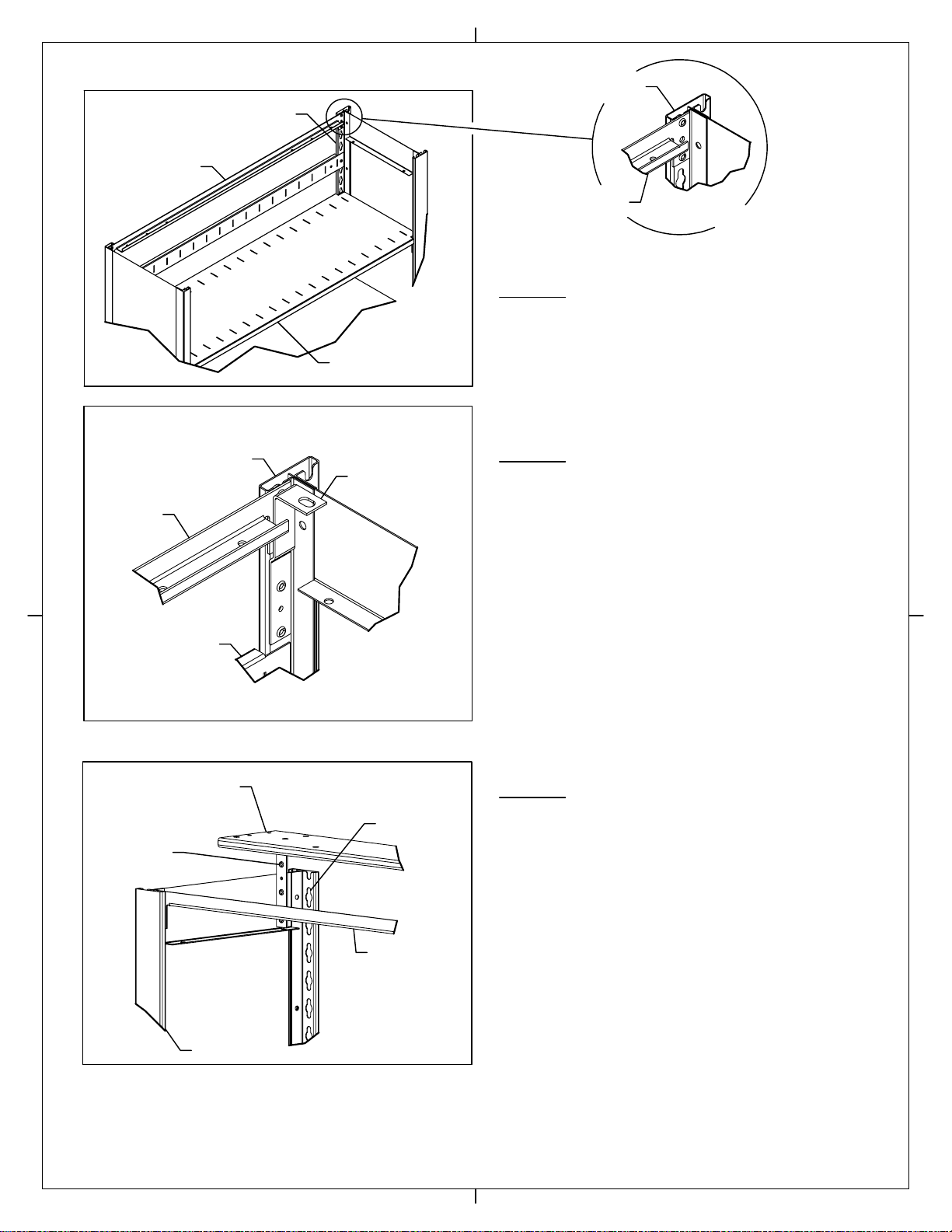
Figure H
Detail I
Figure J
Step 8:
Install top cover lock brackets into both uprights as shown
in Figure J by placing rivets of the brackets into first two
keyholes under the shelf support.
Install rear standard shelf support for top panel by placing
rivets of support into the top two keyholes of the uprights as
shown in Figure H and Detail I.
Step 7:
Step 9:
Install top cover front support channel by placing top rivet
on each side of channel into the first complete keyhole in
the top of both uprights as shown in Figure K.
Figure K
Upright
Standard
Shelf Support
Top Shelf
Top of
Upright
Shelf
Support
Top Cover
Lock Bracket
Upright
Cover Shelf
Support
Back Stop
for Top Shelf
First Complete
Keyhole
Shelf
Support
Top Cover Front
Support Channel
Top Rivet
Upright
PAGE 6 OF 31

Figure L
Step 10:
Secure top cover front support channel and both top
cover lock brackets to uprights using #10-24 x 3/8"
screws as shown in Figure L.
Place top cover on unit as shown in Figure M. Unit
should now look similar to Figure N.
Step 11:
Figure M
Figure N
#10-24 x 3/8" Phillips Pan
Head Sheet Metal Screw
#10-24 x 3/8"
Screw Shelf Support
Upright
Top Cover
Top Cover Front
Support Channel
Upright
PAGE 7 OF 31
Top Cover Front
Support Channel
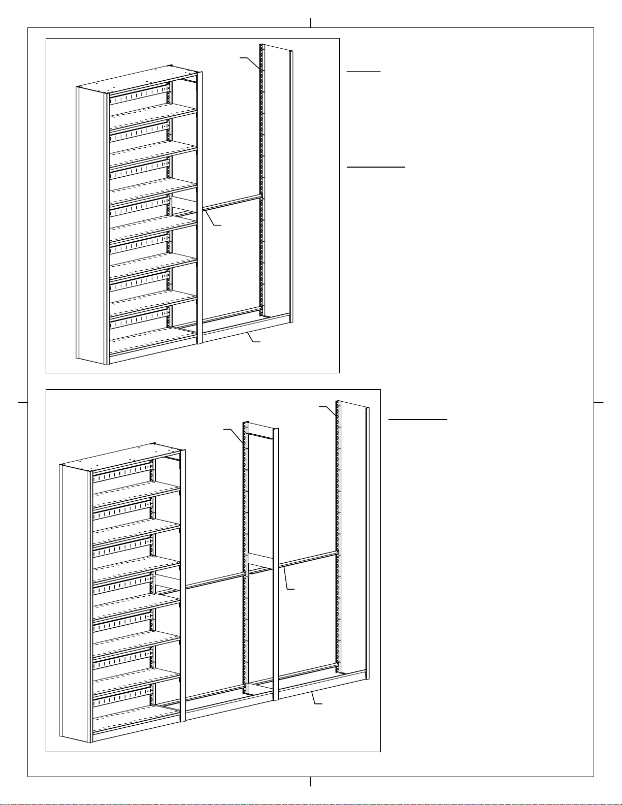
Figure O
Note:
If the stationary shelving section consists of three or more
units (Figure P), skip to Step 12b. If your section consists
of two units only (Figure O), continue here with Step 12a.
Step 12a:
Position a closed 'L' upright to the right of assembled unit
and install shelf supports and kick plate by repeating
Steps 1 & 2 (Figure O). Go to Step 13.
Repeat steps one and two as needed to set up
all units in the section except for the end unit.
For the end unit substitute a closed 'L' upright
for an open 'T' upright (Figure P).
Step 12b:
Figure P
Closed 'L'
Upright
Standard
Shelf
Support
Standard
Shelf
Support
Closed 'L'
Upright
Open 'T'
Upright
PAGE 8 OF 31
Kick
Plate
Kick
Plate

Figure Q
Remove bi-slider (all systems), tri-slider (tri-slide and quad-slide
systems only) and lock bracket knockouts on top cover of first unit
(see Figure Q). Remove knockouts with phillips screwdriver and
rubber mallet or plastic tip hammer.
Step 13:
1/4-20 x 3/4" Hex Bolt
1/4-20 Flanged Hex
Nut
Figure S
Use (3) 1/4-20 x 3/4 hex bolts and (3) 1/4-20 flanged hex nuts to
attach top stablizer channel to top cover of first unit using the first
set of holes in the top cover. Use (1) 1/4-20 x 3/4 hex bolt & (1)
1/4-20 flanged hex nut to secure each top cover lock bracket (see
Figure R).
Step 14:
Step 14a:
Repeat steps 13 & 14 for all units except the end unit which will
not have a stabilzer channel attached during this part of assembly
(See Figure S).
Step 14b:
For Tri/QuadSlider Systems Only, add a second top stabilizer
channel behind channels that were attached in Steps 14 and 14a
(See Figure T).
Step 14c:
For QuadSlider Systems Only, add a third top stabilizer channel
behind channels that were attached in Steps 14, 14a and 14b. You
will need to drill holes to mount this set of channels, maintain
similar front to back spacing as for Bi/TriSlider stabilizer channels.
Figure R
Figure T
Lock
Bracket
Knockout
Top Cover
Lock Bracket
Knockout
Bi-Slider
Knockouts
Tri-Slider
Knockouts
Do Not Attach Channel
To End Unit at This Time
Top Stabilizer
Channel
1/4-20 x 3/4"
Hex Bolts
Top Cover
Top Stabilizer Channel
w/Notch Towards Back
of Unit
Front Set
of Holes
1/4-20 Flanged
Hex Nut
Add Second Set
of Stabilizer Channels only
on Tri/QuadSlider Systems
PAGE 9 OF 31

Parts Required for Typical
Moveable Shelving Section
Stainless Steel
Front Cap
Shelf
Reinforcement
Decking
Welded Rail End Stop
End Cap
Stationary
Connector
Channel
Carriage
Single Rivet
Shelf Support
Back
Stop
Divider
Shelf
Standard
Shelf
Support
Closed 'T'
Upright
Standard
Shelf
Support
Top Cover
Front
Support
Channel
Top Cover
Rear Support
Channel
Tri-Slider
Hat Channel
Tri-Slider
Stabilizer
Bracket
Top
Cover
Lock
Bracket
Safety
Stop
BiSlider
Roller Bracket
Top Cover
PAGE 10 OF 31
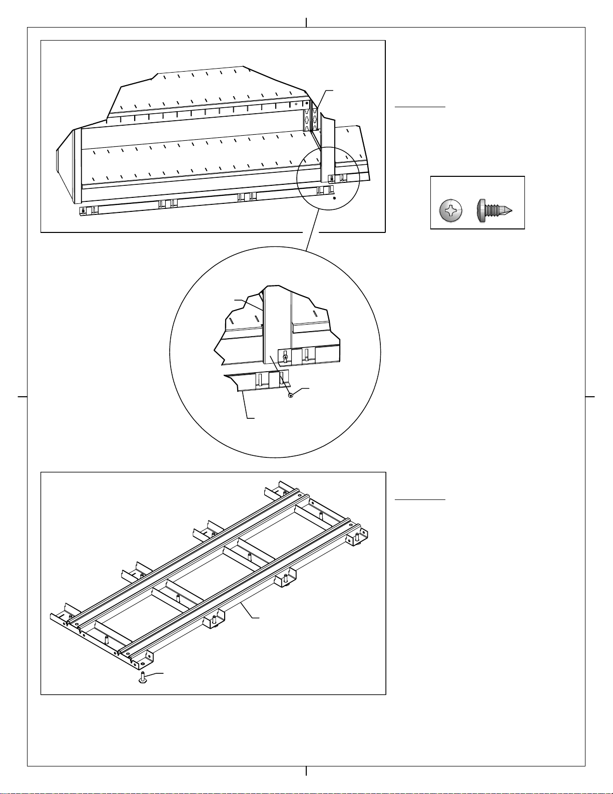
Figure U
Detail V
Figure W
#8 x 3/8" Tek Screw
Step 15:
Position a stationary connector channel in
front of each stationary base unit. Attach each
channel to the uprights of the stationary units
using #8 tek screws as shown in Figure U and
Detail V.
Step 16:
Install (12) leveling glides in each rail
assembly making sure that each glide is
screwed in completely and is flush with the
bottom of the rail assembly (See Figure W).
Stationary
Units
Stationary
Connector
Channel
#8 x 3/8"
Tek Screw
Upright
Leveling Glide
Welded Rail Assembly
Page 11 of 31
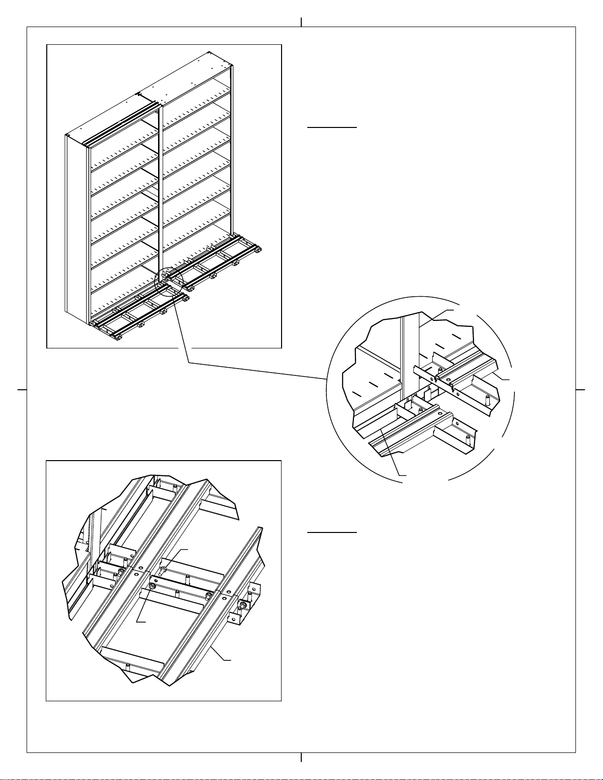
Figure X
Figure Z
Detail Y
Step 17:
Attach a rail assembly to each stationary connector channel.
Rail assemblies have corresponding slots which slide over
connector channel to secure rail assembly into place (See
Figure X and Detail Y).
Step 18:
Join rail assemblies together using (4) 1/4-20 x 3/4" hex bolts
and (4) flanged hex nuts. Make sure rails are flush from one
assembly to the next before tightening bolts (See Figure Z).
-For BiSlider Systems, continue with Step 19
-For TriSlider Systems, skip to Step 20
-For QuadSlider Systems, skip to Step 22
1/4-20
Nut
1/4-20 x 3/4"
Bolt
Rail
Assembly
Upright
Rail
Assembly
Stationary
Connector
Channel
Page 12 of 31
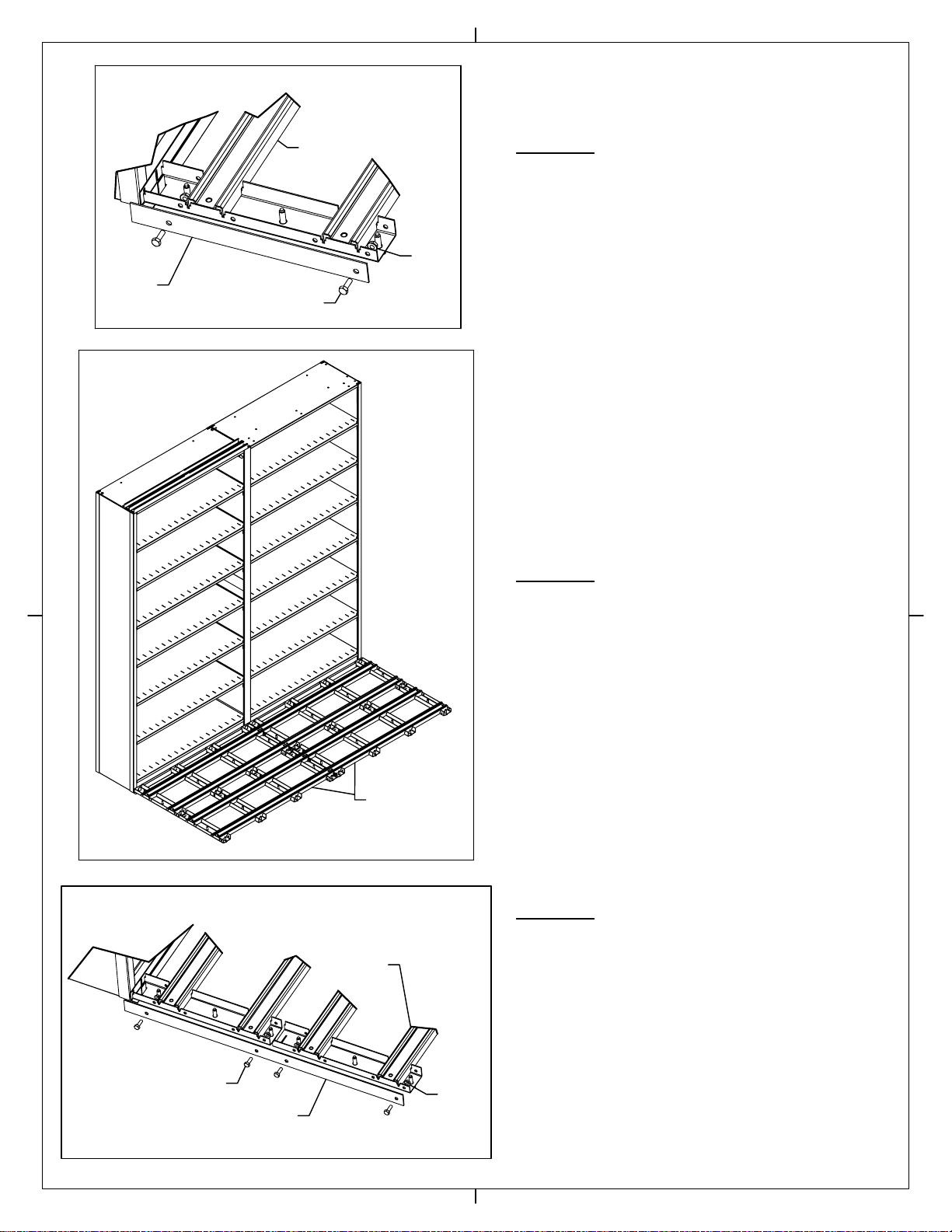
Figure AA
Figure AB
Figure AC
Step 21:
For TriSlider Systems Only
Attach deck end cap to rail assemblies starting from left end
of rail assembly. Use (4) 1/4-20 x 3/4" hex bolts and (4)
1/4-20 flanged hex nuts to secure end cap to rail assembly
as shown in Figure AC. Repeat for right side of system.
Skip to Step 24.
Position additional row of rail assemblies in front of Bi-Slider
rail assemblies that were already in place as shown in
Figure AB. Join second row of rail assemblies to each other
with 1/4-20 hardware as instructed in Step 18 for first set
of rails.
Step 20:
For TriSlider Systems Only
Attach deck end cap to rail assembly starting from left end
of rail assembly. Use (2) 1/4-20 x 3/4" hex bolts and (2)
1/4-20 flanged hex nuts to secure end cap to rail assembly
as shown in Figure AA. Repeat for right side of system.
Skip to Step 24.
Step 19:
For Bi-Slider Systems Only
1/4-20
Nut
Deck End
Cap
Rail
Assembly
1/4-20 x 3/4"
Bolt
Additional Rail
Assemblies
1/4-20
Nut
1/4-20 x 3/4"
Bolt Deck
End Cap
Rail
Assembly
Page 13 of 31

Figure AD
Figure AE
Attach deck end cap to rail assemblies starting from left end
of rail assembly. Use (6) 1/4-20 x 3/4" hex bolts and (6)
1/4-20 flanged hex nuts to secure end cap to rail assembly
as shown in Figure AE. Repeat for right side of system.
Step 23:
For QuadSlider Systems Only
Position (2) additional rows of rail assemblies in front of
Bi-Slider rail assemblies that were already in place as shown
in Figure AD. Join second & third rows of rail assemblies to
each other with 1/4-20 hardware as instructed in Step 18
for first set of rails.
Step 22:
For QuadSlider Systems Only
Additional Rail
Assemblies
1/4-20
Nut
1/4-20 x 3/4" Bolt
Deck End Cap
Rail Assembly
Page 14 of 31

Figure AF
Detail AG
Detail AH
Install unit decking. Deck sections interlock with rail
assemblies and should be flush with the top of the rails
when installed (See Figure AF). After decking is in place,
install end stops at the end of each rail using (1) 1/4-20 x
1/2" cap screw (See Figure AF).
Step 25:
Step 24:
LEVELING OF UNIT
Determine highest point on rail assembly. Working out from
this point, level rails by adjusting leveling glides. For
system to function properly all rails must be level
from left-to-right, front-to-back, and rail-to-rail. All
leveling glides must be in contact with the floor.
Step 26:
Remove protective film from stainless steel front cap before
attaching to rail assembly. Position cap with notches towards
floor, then attach to each rail section by snapping into place
over front rail crossmembers (See Details AG & AH).
1/4-20 x 1/2" Allen
Head Cap Screw
See Details AG & AH
Leveling Glides
Decking
Rail Cross-
Member
Stainless Steel
Front Cap
Notched Side
Rail Assembly
Stainless Steel
Front Cap
Rail Assembly
1/4-20 x 1/2"
Cap Screw
End
Stop
Rail
Assembly
Page 15 of 31
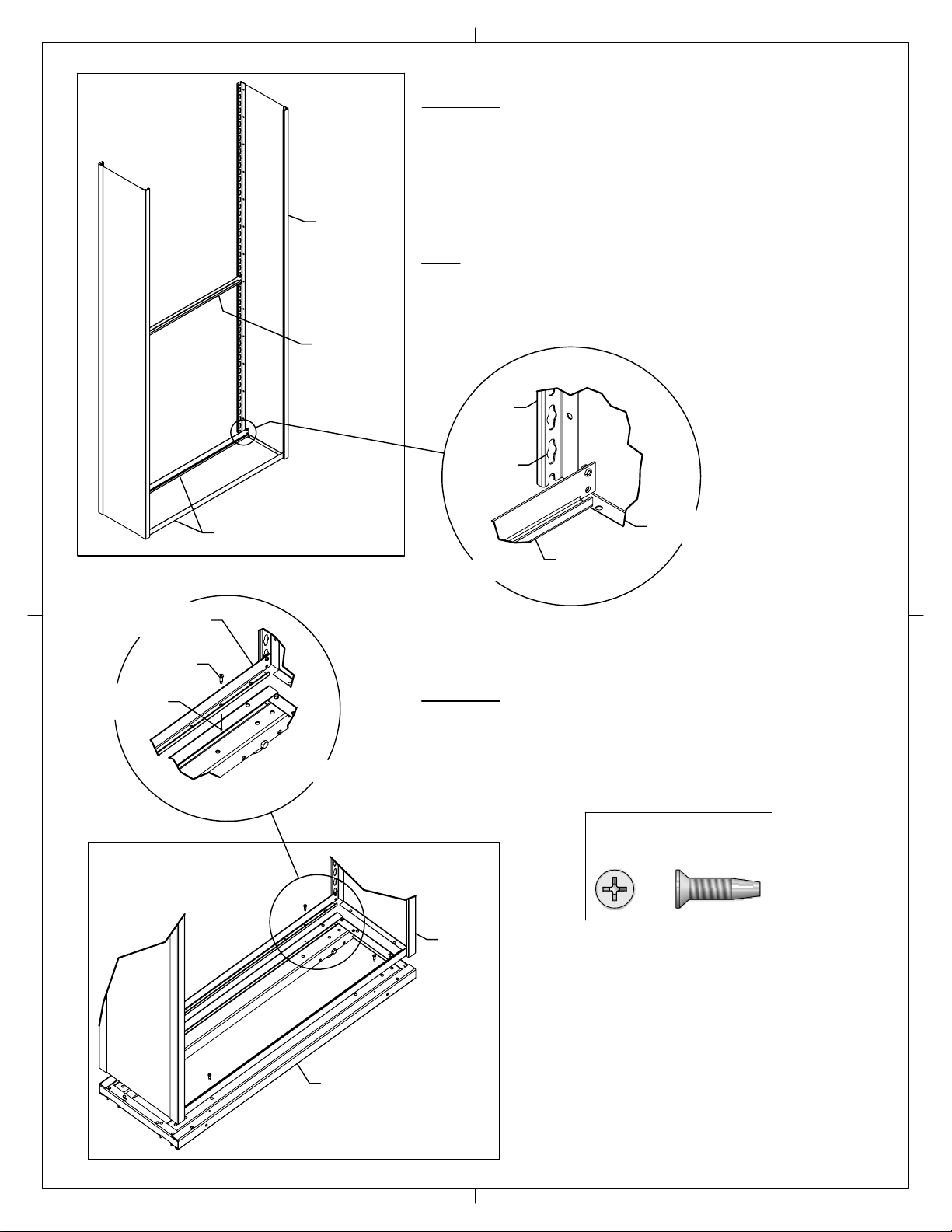
Figure AI
Detail AJ
Detail AL
Figure AK
#10 x 3/4" Flat Head
Tek Screw
Fasten the shelving unit assembled in the previous step to a
carriage using (4) #10 x 3/4" flat head tek screws (See Figure AK
& Detail AL).
Step 28:
Note: Single rivet shelf supports are used only for the bottom
shelf on units that will be attached to a carriage. Standard shelf
supports are used for the rest of the unit.
Temporarily mount a shelf support at chest height between (2)
closed 'L' uprights to hold them in position. Check to make certain
that the flanges on the uprights are at the bottom of the unit.
Mount (2) single rivet shelf supports into the first complete set of
keyholes at the bottom of the uprights (See Figure AI & Detail AJ).
Step 27:
Closed
Upright
Standard
Shelf Support
Single Rivet
Shelf Supports Flange at Bottom
of Upright
Single Rivet
Shelf Support
First
Complete
Keyhole
Upright
#10 x 3/4"
Screw
Single Rivet
Shelf Support
Pre-Punched Hole
in Carriage
Shelving
Unit
Carriage
Page 16 of 31
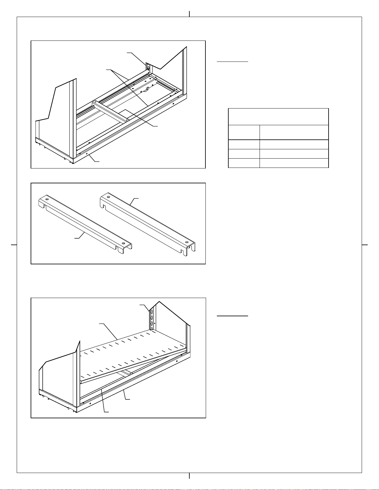
Figure AM
Figure AN
Figure AO
Step 29:
Install heavy duty shelf reinforcements for the bottom
shelf as shown in Figure AM. See Table 2 for proper
number of reinforcements. Figure AN shows the visual
difference of a standard shelf reinforcement compared
to a heavy duty reinforcement.
Step 30:
Install bottom shelf by tilting as shown in Figure
AO. It should then lie flat on shelf supports and
reinforcement(s).
18"
Depth of
Shelving
12"
15"
Table 2 - Shelf Reinforcements
for Mobile Section - Bottom Shelf
Number of Heavy Duty
Reinforcements
One
Two
One
Heavy Duty Shelf
Reinforcement
Carriage
Single Rivet
Shelf Supports
Upright
Standard Shelf
Reinforcement
Heavy Duty Shelf
Reinforcement
Shelf
Upright
Shelf Support
Carriage
Page 17 of 31

Figure AP
Figure AQ
Figure AR
Step 31:
Install back stop for bottom shelf. Count up three
complete keyholes from top of shelf and place rivets of
back stop into these keyholes (See Figure AP).
Step 32:
Install (2) standard shelf supports at the correct locations
based on unit configuration. See Figure F on Sheet 5 for
guidance on shelf spacing.
Step 33:
If required (See Table 3) install standard shelf
reinforcement(s) as shown in Figure AR.
Two
None
Number of
Reinforcements/Shelf
Table 3 - Shelf Reinforcements
for Mobile Section
None
12"
15"
18"
Depth of
Shelving
Back
Stop
Standard
Shelf Supports
Standard Shelf
Reinforcement
Page 18 of 31

Figure AS
Figure AT
Figure AU
Step 34:
Install second shelf by tilting as shown in Figure AS. It
should then lie flat on shelf supports and reinforcement(s).
Step 35:
Install back stop for second shelf. Count up three complete
keyholes from top of shelf and place rivets of back stop into
these keyholes (See Figure AT).
Step 36:
Install remainder of shelf supports, shelves, back stops, &
shelf reinforcements (if required), working from bottom to
top. Keep in mind your installation may be different, as shelf
spacing varies from job to job (See Figure F on Sheet 5 for
typical configurations). Do not install components at the top
of unit at this time; when complete the assembled unit
should look similar to Figure AU.
Shelf
Shelf
Support Back
Stop
Fourth Opening Typically
Has Posting Shelf on
Letter/Legal Systems
Page 19 of 31
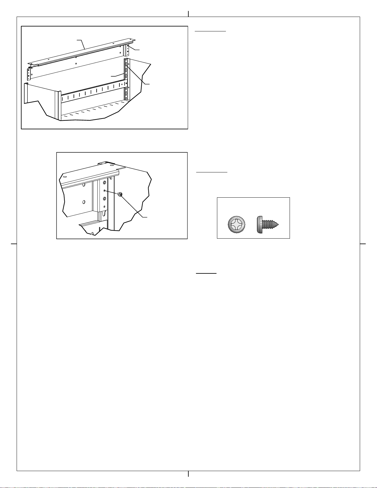
Figure AV
#10-24 x 3/8" Phillips Pan
Head Sheet Metal Screw
Figure AW
Step 37:
Place the rivets of the top cover rear support channel into the
keyholes at the top of the upright at the rear of the unit. The
top rivet on each side should be inserted into the first complete
keyhole at the top of the uprights (See Figure AV). Tap channel
into place with rubber mallet or hammer to seat rivets firmly
into bottom of keyholes.
Step 38:
Use (2) #10-24 x 3/8" phillips pan head screws to secure
channel to uprights as shown in Figure AW.
Note:
For BiSlider carriage assembly, continue with Step 39.
However, if you have finished assembling all BiSlider
carriages and are now assembling Tri-QuadSlider
carriages, skip forward to Step 50.
Upright
Top Cover Rear
Support Channel
Top Complete
Keyhole
Top
Rivet
#10-24 x 3/8"
Screw
Page 20 of 31
Table of contents
Other Datum Storage Indoor Furnishing manuals


Popular Indoor Furnishing manuals by other brands


Politorno
Politorno Fenix 1181 Assembly instructions

Julian Bowen Limited
Julian Bowen Limited WYO001 Assembly instructions

Dorel Home Products
Dorel Home Products DA2071369 Instruction booklet

Southern Enterprises
Southern Enterprises MS9350 manual

Furniture of America
Furniture of America FGI-19801C24 Assembly instructions

Birlea
Birlea DAKOTA Assembly guide


