DAVIS Universal Shelter User manual

Universal
Shelter
USER
MANUAL
Davis Instruments, 3465 Diablo Avenue, Hayward, CA 94545-2778 U.S.A. • 510-732-9229 • www.davisinstruments.com
R
For all Davis weather consoles including Vantage Pro2 ,
Vantage Pro2 Plus , Vantage Vue , Weather Envoy
and EnviroMonitor IP Gateway
™
™R
R
Product Number 6618


1
Welcome to Universal Shelter
(product no. 6618)
The Universal Shelter allows you to shelter your Vantage Pro2 or Vantage Vue
console, EnviroMonitor IP Gateway, or Weather Envoy for remote or field
installations. It has been carefully designed to allow for the mounting of all Davis
weather station consoles and Envoys, and can be used with Solar Power Kits. The
weather resistant housing can also be used to house batteries or other field
equipment.
Contents of Package
The package contains the following:
• Weather-proof shelter
• Hardware kit (as shown)
Tools for Setup
• Adjustable wrench or 7/16” wrench
• Drill and 3/16” (5 mm) drill bit (if mounting on a vertical surface)
• Phillips head screwdriver
Weather-Resistant
Housing
Hardware Kit
1/4" Lock Washers
1/4" Hex Nuts
U-Bolts
Backing Plates
2 Split Grommets,
(with oval cable opening)
1/4" x 1 1/2"
Lag Screws
#6 3/8” Pan Head
Philips Screws

2
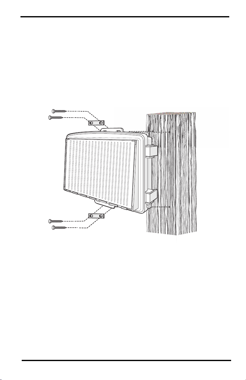
Install the console, IP Gateway or Envoy in
the shelter
Note: You may mount the shelter before installing the device. However, it may be easier to do
this at a workbench rather than in the field.
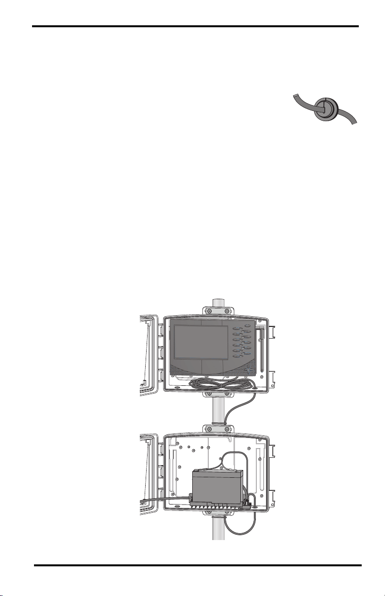
The shelter has been designed to fit Davis consoles. Inside the shelter, outlines of
the Vantage Pro2 console, Vantage Vue console, and Envoy will indicate where
they will be mounted in the shelter.
1. Before mounting a Vantage Vue console, remove the kickstand. Before
mounting a Vantage Pro2 console or Envoy, point the antenna down.
2. The holes to use for mounting your console or Envoy are marked: VP2 for
Vantage Pro2 console, VV for Vantage Vue console, and E for Envoy. For IP
Gateway, use top Vantage Pro2 hole.
3. Screw the two (one for IP Gateway) 1/2” pan head screws into the correct
holes. The depth of the hole has been specifically designed so that the screw
will “bottom out” at the correct depth.
Note: You may need to adjust the screw height for proper fit.
4. Using the keyhole(s) on the back of the console, Envoy, or IP Gateway, slide
the device onto the screws and move it down to lock into position.(Note: use
just one screw for IP Gateway.)
5. Close and lock the shelter.
Outline and screw holes for
mounting a Vantage Vue Console.
Outline and screw holes for
mounting a Weather Envoy
Outline and screw holes for
mounting a Vantage Pro2 Console.
E
E
VV VV
VP VP
ENVOY Vantage
VUE
Vantage
PRO2
Outline and screw holes for
mounting an EnviroMonitor IP Gateway
E
E
VV VV
VP VP
ENVOY Vantage
VUE
Vantage
PRO2
E
E
VV VV
VP VP
ENVOY Vantage
VUE
Vantage
PRO2
E
E
VV VV
VP VP
ENVOY Vantage
VUE
Vantage
PRO2

3
Routing Cables from the Shelter
If you mount a cabled console or Envoy or IP Gateway in the shelter, or are using
the shelter with a Solar Power Kit, or otherwise need to route cables from inside
the shelter, follow these steps:
1. Remove one of the rubber plugs from the floor of the
shelter.
2. Feed the cable down through the hole.
3. Outside the shelter, wrap a split grommet around the cable.
4. Push the grommet securely into the hole in the floor of the
shelter.
Using the Universal Shelter with a Solar
Power Kit
For some installations, you will need both a Solar Power Kit and a Universal
Shelter. For example, if you wish to power a cabled Vantage Pro2 console, you
will need a Heavy Duty Solar Power Kit (#6612). However, there is not enough
room in the kit’s shelter for both the large battery and the console. You will need to
mount your console in a Universal Shelter and connect it to the Heavy Duty Solar
Power Kit.
1. Install the console in the Universal Shelter.
Use oval-hole
gromment with
at cables or
power cable.

4
2. Remove the plug from one of the holes in the floor of the Universal Shelter.
Wrap the split oval grommet around the console power cable and feed it up
through the hole. Insert the grommet snugly into the hole.
3. Plug the power cable into the console.
4. You may want to mount the two shelters at this point, within cable-length (the
console power cable that comes with the Heavy Duty Solar Power Kit is 10'
[3 m] long) of each other. See Mounting the Universal Shelter (page 4). See
your Solar Power Kit User Manual for information on installation.
5. Remove the plug from one of the holes on the floor of the Heavy Duty Solar
Power Kit shelter.
6. Wrap a split-oval grommet around the other end of the console’s power cable
and feed it up through the hole in the Heavy Duty Solar Power Kit shelter.
Insert the grommet snugly into the hole.
7. Plug the power cable into the console power plug on the charging circuit.(See
your Solar Power Kit User Manual.)
8. Close both shelters and lock them.
Mounting the Universal Shelter
Choose a location for your shelter. It can be mounted on a pole or a flat surface
such as a wall or a wooden post.
Mounting on a Pole
Mount the shelter onto a pole or pipe with an outside diameter of 0.84'' to 1.84''
(21 mm to 27 mm) using the U-bolts, backing plates, washers, and hex nuts
provided.
Note: For mounting on larger diameter pipes, the housing can accommodate U-bolts with 5/6''
(8 mm) threads for pipes up to 2.40'' (61 mm) outside diameter (not provided).

5
1. While holding the shelter against the pole, place a U-bolt around the pole and
through the two holes at the top of the shelter.
2. Place a backing plate, a washer, and a hex nut on each of the bolt ends.
3. Tighten the nuts using an adjustable wrench or 7/16'' wrench.
4. Place the second U-bolt around the pole and through the two holes at the
bottom of the shelter. Put a backing plate, a washer, and a hex nut on each bolt
end, and tighten the hex nuts.
Mounting on a Post or Flat Surface
Attach the shelter to the mounting surface in the desired location using the large
screws and backing plates as shown below. Use a pencil or a center-punch to mark
the location of the pilot hole.
1. With a 3/16'' (5 mm) drill bit, drill two holes approximately 2"(50 mm) apart.
Use a carpenter’s level to ensure the holes will be level.
2. Drill two more holes 7-1/32'' below the upper holes.
3. Insert the 1/4'' x 1-1/2'' lag screws through the washers, backing plates, and
through the holes at the top of the shelter into the post.
4. Using an adjustable wrench or 7/16'' wrench, tighten the lag screws.
5. Repeat steps 3 and 4 for the bottom of the shelter.

Universal Shelter
Product Number 6618
Document Number: 07395.328 Rev. B, May 12, 2021
Vantage Pro®, Vantage Pro2™, Vantage Vue®, EnviroMonitor®and Weather Envoy™are
trademarks of Davis Instruments Corp., Hayward, CA.
© Davis Instruments Corp. 2021. All rights reserved.
Information in this document subject to change without notice. Davis Instruments Quality
Management System is ISO 9001 certified.
3465 Diablo Avenue, Hayward, CA 94545-2778 U.S.A.
510-732-9229 • Fax: 510-732-9188
Contacting Davis Technical Support
For questions about installing or operating your Universal Shelter,
please contact Davis Technical Support. We’ll be glad to help.
Note: Please do not return your unit for repair without prior authorization.
Specifications
Housing Material . . . . . . . . . . . . . . . . . Rugged ASA Plastic
Dimensions (width x length x height) . .13.75 X 10 X 4.15 inches;
34.9 X 25.4 X 10.5 cm
Weight . . . . . . . . . . . . . . . . . . . . . . . . .2.30 lbs.; 1.04 kg
Online www.davisinstruments.com
See the Weather Support section for copies of user
manuals, product specifications, application notes,
software updates, and more.
E-mail [email protected]
Telephone (510) 732-7814
Monday - Friday, 7:00 a.m. - 5:30 p.m. Pacific Time.
This manual suits for next models
1
Table of contents
Other DAVIS Enclosure manuals