Davnor SA 60 Instruction manual

i
Automated Surface Water Treatment
System
INSTALLATION, OPERATIONS &
MAINTENANCE MANUAL

ii
Table of Contents
1. Introduction ......................................................................................................1
2. Operations Summary .......................................................................................1
3. Assembly..........................................................................................................2
4. Filter Media Installation ....................................................................................6
5. System Commissioning....................................................................................7
6. Sanitizing Procedure........................................................................................8
7. System Start-Up...............................................................................................9
8. Operation .........................................................................................................9
9. Filter Maintenance..........................................................................................10
10. Degassing the Filter Media...........................................................................11
11. Winterization ................................................................................................11
12. Refilling ........................................................................................................12
13. Decommissioning / Moving ...........................................................................12
14. Trouble Shooting...........................................................................................13

1
1Introduction
Davnor Water Treatment Technologies Ltd. has developed a treatment system featuring an
intermittently operated slow sand filtration process. It is based on the continuous slow sand
filtration process that has been used for over 100 years. The BioSand Water Filter has
proven effective in removing iron (and iron bacteria), manganese, sulphur odours and other
obnoxious smells, turbidity, colour, bacteria, viruses and water borne parasites from drinking
water supplies. Do not attempt to treat wastewater, heavily polluted or contaminated water.
Please contact a Davnor representative if there is any uncertainty regarding the treatability
of the water.
2Operations Summary
The Davnor Water Treatment Technologies Ltd. surface water system is a slow sand
filtration process. The operation of the system is automated for the removal of giardia
cysts, cryptosporidia oocysts, other water borne parasites, bacteria, viruses, turbidity
and colour. The water is pumped or gravity fed to the filter. The water flows by gravity
through the filter and then the filtered water flows to a storage tank and is re-pressurized
for use or further treatment.

2
3Assembly
Important Note: Read the full set of instructions before beginning assembly.
You will be required to provide the following:
•Connection to the untreated water source
•120 V electrical outlet for the pump and the solenoid valve
•Connection to the distribution line
•Connection to a drain or sump for drainage and overflow lines (optional drainage
packages are available)
Locate System Components
•Ensure you have all the required parts and materials for assembling the system
(figure 3-1).
•Arrange the components for ease of installation and maintenance. Consider the
location of the untreated water inlet, floor drain or drainage pipe and electrical outlet.
•Place the filter on the stand, place the storage tank, pump and pressure tank.
Note: A qualified plumber should make the connection from the untreated water inlet to
the filter system and the filtered water outlet to the distribution line. Your pump and your
solenoid valve may need to have electrical plugs attached to them. This work should be
performed by a qualified electrician.
•Install a system bypass in case there is ever a need to take the system off line.
Table 1- Flow Rates and Dimensions
Model No.
Flow Rate (nominal)
Filter Dimensions
Storage Tank
L/m
gpm
Diameter (cm)
Height
(cm)
Capacity
(gallons)
Dimensions
(cm) LWH
Top
Bottom
SA 60
1
0.25
49
29
94
200
150 x 70 x 90
SA 120
2
0.5
64
42
94
200
150 x 70 x 90
SA 240
4
1.0
78
58
94
200
150 x 70 x 90

3
24
19 20
18
13
17
4
2
8
1
11
16
5
6
7
26
27
12 25
15
9
14
10
23 22
3
21
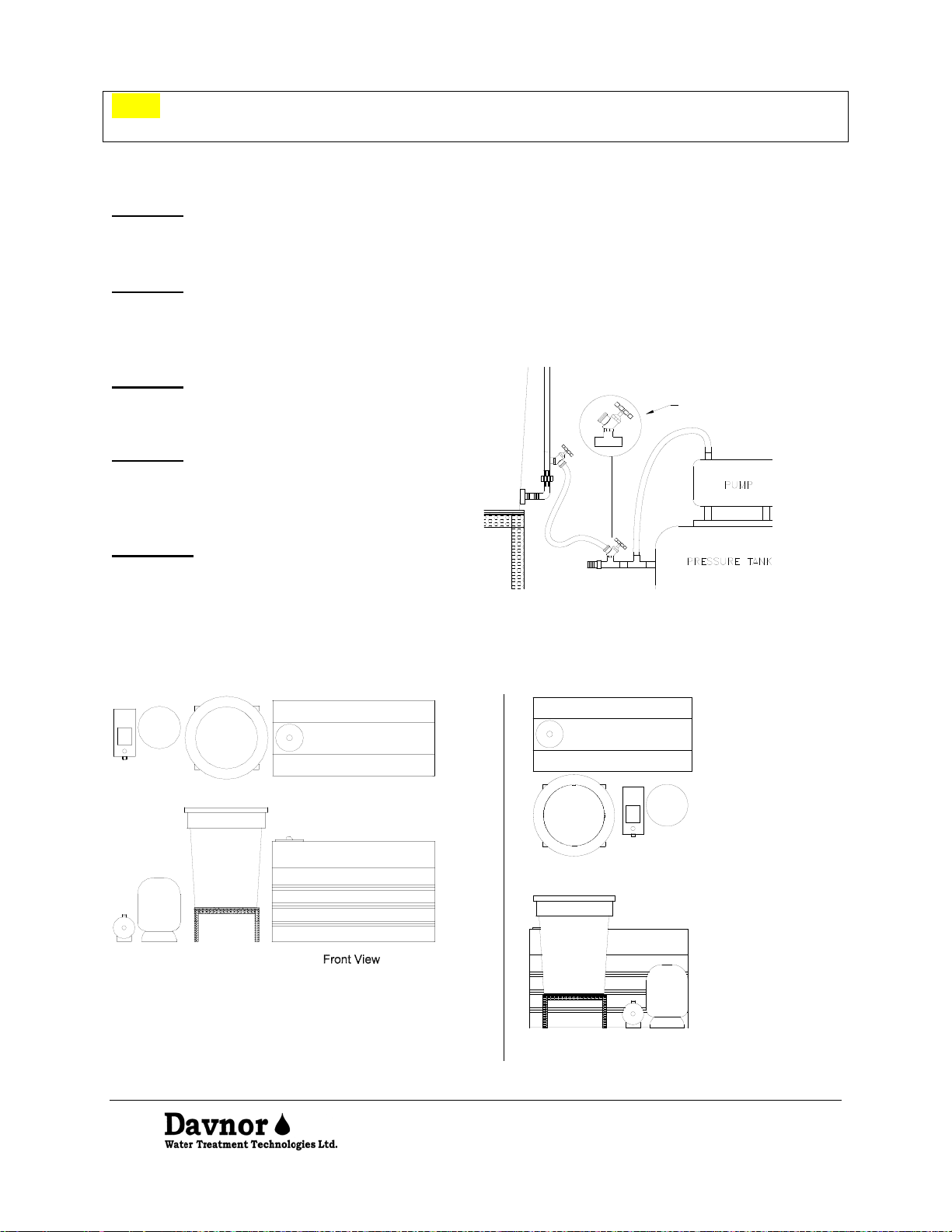
Figure 3-1 Automated System Layout
1. BioSand Filter
2. Filter Stand
3. Storage Tank
4. Raw Water Inlet
5. Filter Inlet Valve
6. Filter Float Valve with Union Connection
7. Clean In Place (CIP) and Diffuser Basin
8. Underdrain
9. Flow Rate Control Valve
10. Filter Standpipe
11. Standpipe Union Connection
12. Standpipe Lower Valve
13. Maintenance Drain Valve
14. Filter Outlet Valve
15. Anti-siphon Valve
16. Filter Overflow
17. Solenoid Valve (to high level float switch)
18. Storage Tank Inlet Valve with Union
Connection
19. Sampling Valve
20. Storage Tank Float Valve
21. High Level Float Switch (to the solenoid valve)
22. Low Level Float Switch (to the pump)
23. Storage Tank Outlet with Union Connection,
Shutoff Valve and Drain Valve
24. Check Valve
25. Pump Electrical Outlet (to the low level float
switch)
26. Clean In Place (CIP) Reverse Flow (attached to
standpipe lower valve)
27. To Distribution or Further Treatment (softener,
Reverse Osmosis, UV)

4
Important Notes:
•All of the assembled components have been loosely fitted together. Use
Teflon tape on all threaded connections and tighten. Do Not Over-Tighten the
PVC fittings. (They will crack if over-tightened)
•Refer to Figure 1 to find the locations for all system components.
•Heat the end of hose connections in hot water before installing. Use the gear
clamps to fasten the hose to the barb fitting.
Install Assembled System Components
Step 1. Locate and attach the BioSand water filter assemblies.
•
Inlet assembly.
•Maintenance drain valve
•Overflow assembly
•Standpipe
Step 2. Locate and attach the filtered water storage tank assemblies.
•Inlet assembly.
•Outlet assembly.
•Overflow assembly.
Step 3. Place the pump and pressure tank.
Step 4. Install the low level and high level float switches in the storage tank shown in
Figure 3 -1. To do this, start by removing the supporting ring on the manway of the
filtered water storage tank. Position the low level switch near the bottom of the filtered
water storage tank and the high level switch near the top. Use the notched grooves to
locate the cords for the switches. Replace the supporting manway ring to hold the level
switches in place.
Piping Connections
Step 5. Using the ¾” braided hose for connection between the barbed fittings;
•Connect the raw water supply to the solenoid valve inlet.
Look for the flow direction on the solenoid body.
•Connect the solenoid outlet to the filter inlet.
5
Note: The solenoid can either be attached directly to the filter inlet or mounted to the
filter stand or another convenient location.
•Connect the filter outlet at the filter outlet valve to the filtered water storage tank
inlet.
Step 6. Using the 1” braided hose for connection between the barbed fittings;
•Connect the filtered water storage tank outlet to the pump inlet.
•Connect the pump outlet to the pressure tank.
Step 7. Connect the overflows to the floor drain or sump. Use a separate drain line for
the filtered water storage overflow. This will prevent a cross connection between the
filter and the filtered water storage tank. Leave an air space between the overflow drain
line and the drain to prevent the drain from backing up into your filter.
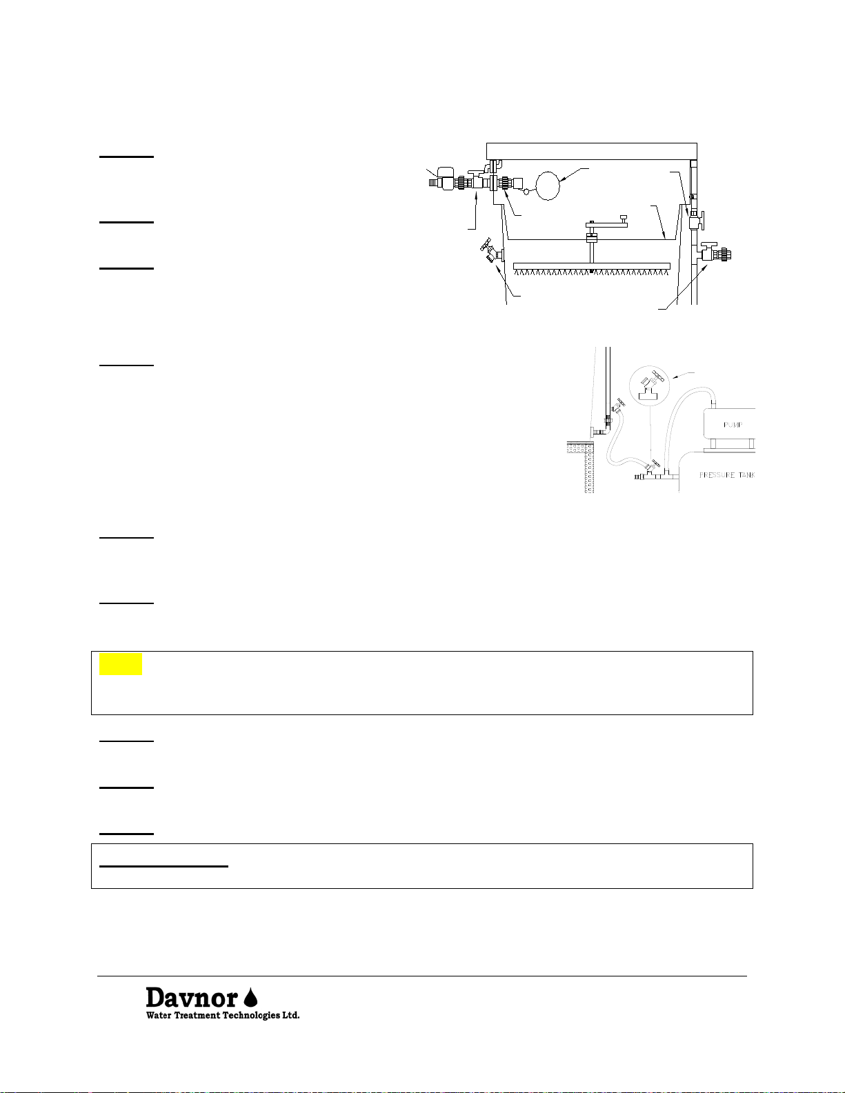
Step 8. Install the filter CIP reverse flow
assembly downstream of the pump (figure
3-3).
Step 9. Connect the hose from the CIP
reverse flow valve downstream of the
pump to the lower valve on the filter
standpipe.
Step 10. Connect the filtered water outlet
downstream of the CIP reverse flow to the
distribution system.
CIP reverse
flow assembly
Figure 3-3
Figure 3-4 Typical System Layouts
Top View
Filter
BioSand
Pump
&
Pressure
Tank
Filter
BioSand
Storage Tank
Filtered Water
Storage Tank
Filtered Water
Pump
&
Pressure
Tank
Front View
BioSand
Filter
BioSand
Filter Storage Tank
Filtered Water
Top View
Filtered Water
Storage Tank

6
4Filter Media Installation
Step 1. Leak test the filter. Close all valves
except the flow rate control valve and fill the
filter with water to the maximum water level.
Drain the filter and repair any leaks before
installing the filter media.
Step 2.
Ensure all the filter valves are
closed. Fill the filter 1/3 full with water. You
can use the water you will be filtering for this
purpose.
Note:Always add the sand to water in
order to prevent air locking in the sand
bed of the filter. The sand should be
poured quickly to prevent lensing,
which will reduce the filter’s flow rate.
You will need to add more water as the
sand is being added. When adding
additional water, pour it through the
diffuser to prevent mixi
ng of
previously installed sand layers.
Approximately 15 cm of water above
the sand is desirable.
Step 3.
Add the underdrain gravel to the
level indicated (figure 4-1).
Step 4.
Level the surface of the
underdrain gravel. Referring to Figure 4-
1, add the #3 sand to the le
vel indicated
on the filter body. Repeat this procedure
with the #2 sand and the #1 sand.
Note: There may be more sand than
required. Do not over fill the sand levels.
However, since the #2 sand tends to settle,
it is acceptable to overfill the #2 sand by a
centimetre above the indicated level.
Underdrain Gravel
Paused Water Level
Maximum Water Level
#3 Sand
#2 Sand
#1 Sand
8cm
5cm
35cm
5cm
Figure 4-1 Filter Media and Filter Water Levels
Step 5. After all of the media has been installed, use the maintenance drain on the side
of the filter to drain the dirty water off the surface.
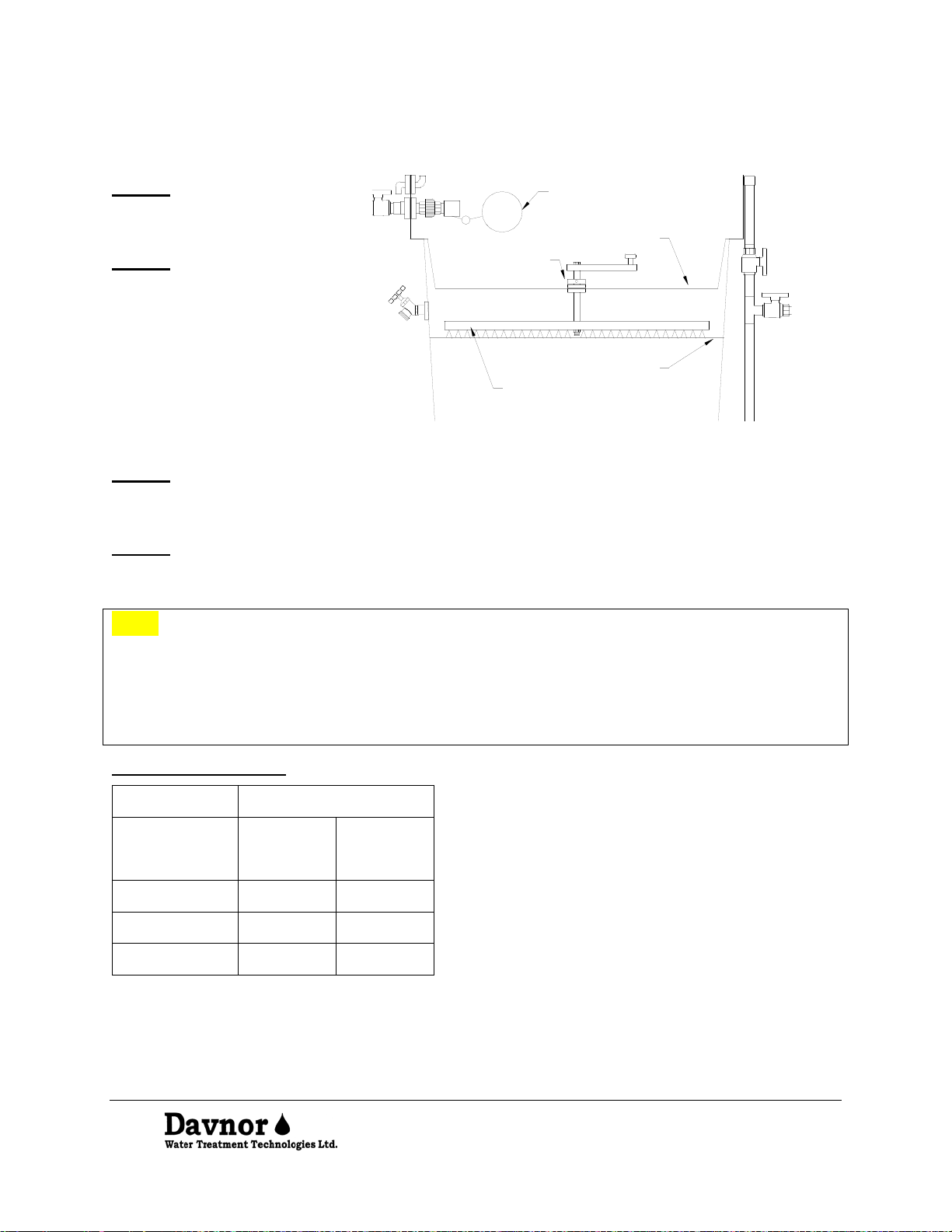
7
5System Commissioning
Step 1. Begin by ensuring all
valves are in the closed
position.
Step 2.
Place the diffuser
basin into the filter. Adjust the
height of the CIP cleaning
arm, using the set screw
collar, so that it rests on the
surface of the filter media.
Attach t
he filter float valve
(figure 5-1).
Surface of filter media
Set screw collar
Diffuser basin
CIP cleaning arm
Filter float valve
Figure 5-1
Step 3. Plug the solenoid valve electrical outlet into the storage tank upper float switch in a
piggyback fashion and plug into the wall outlet. Test the solenoid by moving the upper float
switch. The solenoid valve should open when the float switch is moved to the down position.
Step 4. Open the filter inlet valve to begin filling. Adjust the mechanical float valve in the
filter such that the water level does not go higher than the filter overflow. Now wait until the
water level reaches the maximum water level in the filter (Figure 4-1).
Note: See Table 2 to obtain the filter flow rate. It is critical that the filter be operated at this
flow. Faster flows will compact the upper sand layer, increase filter maintenance
requirements, and may cause poor filter performance. To ensure that this flow rate is
maintained the flow rate control valve should be set for the nominal flow rate as described in
the following steps and not moved from that position unless there is a significant change in
the inlet water temperature.
Table 2- Flow Rates
Model No.
Flow Rate (nominal)
L/m
gpm
SA 60
1
0.25
SA 120
2
0.5
SA 240
4
1.0

8
Step 5. Open the anti-siphoning
valve. Close the storage tank
inlet valve. Op
en the sampling
valve at the storage tank inlet
(Figure 5-
2). Be prepared to
collect water from this point
during the next step.
Step 6.
Set the flow rate by
adjust
ing the flow rate
adjustment valve on the
standpipe. until the flow through
the sampling valve matc
hes the
value in Table 2. The flow can
be measured by timing how long
it takes to fill a 2-litre pop bottle.
Anti-siphoning
valve
Storage tank
inlet valve
Filter outlet
valve
Sampling
valve
Flow rate
adjustment
valve
Figure 5-2
Step 7. Connect a hose to the sampling valve at storage tank inlet and begin flushing water
through the filter. Flush the filter until the water becomes clear. Close the sampling valve.
6Sanitizing Procedure
Care is taken during the manufacture of your water filter to keep it clean and sanitary.
However, during shipping, storage, installation and operation, bacteria could get into the
water filter piping. For this reason, sanitizing is recommended after installation. On
some water supplies, additional periodic sanitizing is also recommended.
Step 1. Prepare a dilute bleach solution for
sanitizing by mixing 5 ml of common household
bleach (Javex, Clorox, etc.) with 1 litre of water.
Step 2. Close the filter inlet valve and allow the
filter water level to drop to the “paused” level.
Close the storage tank inlet valve. Attach the refill
hose to the lower valve on the filter standpipe.
Insert a funnel into the end of the hose. Ensure
the flow rate adjustment valve and the anti-
siphoning valve are open. Open the lower valve
on the filter standpipe (figure 6-1).
Step 3. Hold the end of the hose at the same
height as the top of the filter. Pour the solution
into the funnel. Close the lower valve on the filter
standpipe. Let the solution “sit” for 20 minutes.
This will give sufficient contact time for the
sanitizing solution to kill any bacteria that may be
present.
Standpipe
lower valve
valve
Storage tank
inlet valve
Sampling valve
Refill hose
Flow rate
adjustment
valve
Filter
outlet
valve
Figure 6-1
9
Step 4. Open the filter inlet valve. Flush the sanitizing solution through the sampling
valve.
Note: The filter will not achieve 100% removal of bacteria. If you do not have downstream
chlorine injection bacteria may colonize in the piping downstream of the filter and the storage
tank. Periodic sanitizing of the piping and storage tank will address this problem.
7System Start-Up
Step 1. Open the inlet valve to the filtered water storage tank and continue filtering water.
Step 2. Adjust the low-level float switch in the filtered water storage tank. The low level
float switch should be set such that the water level does not go below the storage tank
outlet. The mechanical float should be set such that the water level does not go above the
storage tank overflow. Adjust the high-level float switch in the filtered water storage tank.
The high-level float switch should be set at a level just below the mechanical float valve.
Step 3. Prime the distribution pump, following the pump manufacturer’s instructions.
Step 4. Plug the pump electrical outlet into the storage tank low level switch in a
piggyback fashion, and plug into the wall outlet. Test the pump by moving the lower float
switch. The pump should operate when the switch is moved to the ‘up’ position.
Step 5. Water should continue to run through the system until the water level in the
filtered water storage tank is just below the overflow. The high-level float switch should
close the solenoid valve and allow the filter to drain to the "paused" water level. The
mechanical float valve will stop the flow of water if the high-level float switch is out of
adjustment. Adjust the mechanical float valve and high-level float switch as required.
Check the system for plumbing leaks and repair as required.
8Operation
Note: In cases where extremely turbid water is being treated, it may be necessary to
perform filter maintenance immediately following installation.
Step 1. The system is operational once the filter flow rate has been set, water has
been flushed through the filter and the standpipe has been sanitized.
Step 2. Ensure the anti-siphoning valve is fully open during normal operation.
Step 3. To test the system, turn on a water source, such as a bath tap. The pump
should start up and draw water from the storage tank.
Step 4. Continue the water demand until you are sure the system is functioning well
and all mechanical floats and storage tank level switches are adjusted as specified.
Step 5. Your BioSand Filter system is now up & running. During normal operation, the flow
rate will decrease as the filter accumulates sediment on the top layer of sand. Once an
acceptable flow rate cannot be maintained, it will be necessary to perform maintenance on
the filter.
10
9Filter Maintenance
Step 1. Close the inlet valve to the filter.
Allow the filter to drain to its "paused"
level before beginning this procedure.
Step 2.
Close the filter outlet valve
(figure 9-1).
Step 3.
Remove the filter float valve
assembly at the union connection.
Anti-siphon
valve
Filter
outlet
valve
Float
valve
Union connection diffuser basin
Maintenance
drain valve
Filter
inlet
valve
Figure 9-1
Step 4. Connect the CIP hose to the CIP reverse flow valve
downstream of the pump. Open the valve to ens
ure that the
flow rate restriction device is limiting the flow rate to
approximately 4 litres per minute to prevent damage to the
filter media. Connect the
other end of the hose to the lower
valve on the filter standpipe (figure 9-
2). Open both valves
and dispel any air in the line through the anti-
siphoning valve.
Close the anti-siphoning valve.
CIP reverse
flow assembly
Figure 9-2
Step 5. Turn the handle on the clean in place (CIP) mechanism to agitate the top of the
sand while the water level is slowly filling from the bottom. Allow the water level to rise
until the diffuser basin is filled with water.
Step 6. Once the diffuser basin is full of water, stop stirring the CIP and wait for 30
seconds. Now flush the dirty water from the sand surface through the maintenance
drain.
Note: It is important to wait for 30 seconds after stirring the sand before flushing the
dirty water off the top of the filter media. This will prevent sand from being lost from the
top layer of the filter media.
Step 7. To restart the filter, close the filter maintenance drain valve, the CIP reverse
flow valve downstream of the pump and the lower valve on the filter standpipe.
Step 8. Re-attach the filter float valve assembly inside the filter. Open the inlet valve to
the filter and the anti-siphoning valve on the filter.
Step 9. Open the filter outlet valve.
SUGGESTION:Keep a maintenance log posted nearby to keep track of when the
filter is maintained.

11
10Degassing the Filter Media
Degassing is part of the normal filter maintenance procedure. In some situations, the
surface of the filter media may appear clean, but there is low flow. This is an indication
the filter media is air locked. This may be due to accidental de-watering of the filter or
the presence of dissolved gases (hydrogen sulphide, carbon dioxide, air, methane) in
the raw water source. Air locking in the filter bed will cause a reduction in the flow rate
through the filter. Remove the trapped gases from the filter media using the following
procedure.
Step 1. Close the filter inlet valve and outlet valve.
Step 2. Remove the filter float assembly at the union connection and remove the
diffuser basin to view the top surface of the sand.
Step 3. Connect the CIP hose to the CIP reverse flow valve downstream of the pump.
Open the valve to ensure that the flow rate restriction device is limiting the flow rate to
approximately 4 litres per minute to prevent damage to the filter media. Connect the
other end of the hose to the lower valve on the filter standpipe (figure 9-2). Open both
valves on the CIP hose and dispel any air in the line through the anti-siphoning valve.
Close the anti-siphoning valve.
Step 4. The water will slowly enter the filter from the bottom, expelling any trapped
gasses through the filter surface. Continue to bottom fill the filter until you don’t see any
more air bubbles surfacing. Be sure to run this for a minimum of 15 minutes to ensure
all gas pockets are filled with water. Periodically tap the sides of the filter during this
process. Drain excess water through the maintenance drain.
Step 5. To restart the filter, close the filter maintenance drain valve, the CIP reverse
flow valve downstream of the pump and the lower valve on the filter standpipe.
Step 6. Replace the diffuser basin. Re-attach the filter float assembly. Open the anti-
siphoning valve and the outlet valve.
11 Winterization
Do not allow the filter system to freeze when it is filled with water. Winterization
consists of the following steps.
Step 1. Perform a complete maintenance cycle on the BioSand Water Filter as
described in Section 9.
Step 2. Unplug the pump.
Step 3. Turn off the water supply and drain the filtered water storage tank and the
plumbing system. Make sure all water is drained from the pump head. (See the pump
manufacturer’s instructions.)
Step 4. Close the outlet valve and anti-siphoning valve.
Step 5. Undo the hose from the lower valve on the filter standpipe. Slowly drain all of
the water out of the sand bed using the standpipe lower valve.

12
12 Refilling the BioSand Water Filter
Step 1. Attach the refill hose to the lower
valve on the filter standpipe. Insert a funnel
into the end of the hose and hold it above the
filter. Pour water into the funnel, allowing
water to fill the filter from the bottom (figure
12-1).
Step 2. The water will slowly enter the filter
from the bottom, expelling any trapped gasses
through the filter surface. Continue to bottom
fill the filter until you don’t see any more air
bubbles surfacing. Periodically tap the sides
of the filter during this process. Drain excess
water off th
e media surface through the
maintenance drain.
Step 3.
To restart the filter, close the
maintenance drain
valve and follow the
procedure outlined in Section 5 of this manual
to start up the entire treatment system.
Standpipe
lower valve
Funnel
Anti-siphon
valve
Storage tank
inlet valve
Sampling valve
Refill hose
Flow rate
adjustment
valve
Filter
outlet
valve
Figure 12-1
13 Decommissioning / Moving
The system can be decommissioned and moved to a new location. Care must be taken to
label all parts and components for ease of re-installation.
Note: Do not move the filter with media in it.
Step 1. Perform a complete maintenance cycle on the filter.
Step 2. Close and disconnect the raw water inlet and the filtered water outlet.
Step 3. Drain the entire system.
Step 4. Disconnect the filter from the storage tank.
Step 5. Remove, clean and label all parts and components from the filter and storage
tank.
Step 6. Remove the filter media. Take care to remove the layers of the media without
mixing. Store the media in clean woven poly bags or plastic pails. Label the media as
it is removed, especially the #1 sand and #2 sand, for ease of re-installation.
Note: The filter media is wet and will be heavy. If desired, new media can be ordered
from Davnor.
Step 7. Follow the system installation instructions to re-install.

13
14 Trouble Shooting
Problem
Possible Cause and Solution
Low flow rate
1. Filter flow rate has slowed due to sediment build up on the top
layer of sand. Perform maintenance on the filter (Section 7).
2. Filter has become air-locke
d due to dissolved gases in the
water coming out of solution. Follow the degassing procedure
(Section 9).
3. Draining the filter below the top of the sand. Fol
low the
degassing procedure (Section 9).
4. Outlet valve has been closed. Ensure that it is open.
5. Surface of sand has become compacted due to excessive
flow rate. Follow the degassing procedure (Section 9).
6. Inlet water temperature has dropped since the flow rate
control valve was last set. Reset the control valve (Section 5).
Note that the valve will
have to be reset again when the water
temperature increases.
Water not entering
the filter
1. Filter inlet valve not fully open. Check the valve to the filter.
2. Mechanical float valve out of adjustment. Re-
adjust as
required.
3. Solenoid valve closed. See sol
enoid valve not functioning
below.
Storage tank
overfilling
1. Mechanical float valve out of adjustment. Re-adjust as
required.
Pump not operating
1. Storage tank low level float switch out of adjustment. Re-
adjust as required.
2. Pump doesn’t have electricity.
Check electrical connection
and breakers.
3.
Valves not open. Check valves on the storage tank and pump
/ pressure tank.
4. Consult the pump manufacturer’s instructions.
Solenoid valve not
functioning
1. Check float switch adjustment. Re-adjust as required.
2. Check electrical outlet. (Solenoid is normally closed)
3. Consult the solenoid manufacturer’s instructions.
This manual suits for next models
2
Table of contents
Popular Water Filtration System manuals by other brands

Fiap
Fiap TrommelSieve Active Series operating instructions

Clean Water Systems
Clean Water Systems Birm 7800 Installation & start?up guide

Dupla
Dupla Perfect Clean PC 1 Instructions for use

Schenker
Schenker SMART 30 Installation, use and maintenance manual

Panasonic
Panasonic ET-SFD320 operating instructions

Delta Electronics
Delta Electronics 20GENG3E Specifications

Katadyn
Katadyn 8018280 Hiker Pro manual

VGE
VGE Xclear UV-C Professional manual

Premier
Premier WP-2 LCV Installation, operation and maintenance manual

AquaTools
AquaTools AT11523 owner's manual

BWT
BWT SOLIFLOW Instructions for installation and recommendation

IMI
IMI norgren F64C Installation & maintenance instructions


