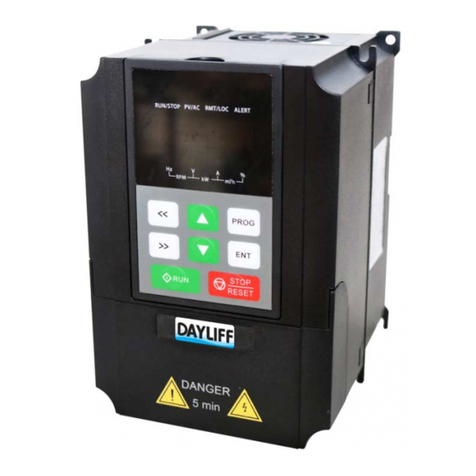
DAYLIFF PVm015 Installation instructions

PUMPVERTER
VFD CONTROLLER
Installation &
Operating Manual

CONTROLLER SPECIFICATIONS
1.
1
2.
SYMBOLS & WARNINGS 2
INDEX
© Davis & Shirtliff Ltd 2022
Contents herein are not warranted
3. WIRING 3
3.3 Controls Terminals Connection
5
4.2 Operational Procedure 7
3.1 Main Circuit Terminals Wiring 3
4. OPERATION 6
3.4 Wiring Main Circuit Installation Accessories
5
4.1 Keypad Description 6
3.2 Main Circuit Wiring 4
5. INVERTER PARAMETER DESCRIPTION 9
6. APPLICATION GUIDANCE 18
6.2 Single Pump Constant Pressure Control 19
6.1 System First Startup/ Troubleshooting Procedure 18
6.3 Multi-pump Constant Pressure Control 20
6.4 Parameter Setting for Master and Auxiliary 21
6.5 Day Part Water Supply Application Setting 26
6.6 Terminal Start/Stop Control Wiring and Setting 28
6.7 Manual/ Auto Control Wiring and Setting 28
6.8 Water Supply Control Using Pressure Switch 29
6.9 Pumping Application 31
FAULTY AND TROUBLE SHOOTING
7.
32
TERMS OF WARRANTY
8.
37

1
1. CONTROLLER SPECIFICATIONS
DAYLIFF Pumpverter drives are high specification VSD's suitable for use in residential and
industrial applications. They are compact and versatile and can be installed in either
motor or wall mounted configuration. The inverter varies pump motor speed with demand
thus regulating pump output to a preset outlet pressure. Particular features include:
• Maintains constant system pressure when water demand changes by use of
pressure transducers
• Can work simultaneously with other units and control up to 6 pumps in cascade
sequence.
• Sleep mode when there is no water consumption for increased energy savings
• Provides complete pump protection against pump overload, low voltage, high
voltage, phase failure, electronics overheating and dry running (when using float
switch).
• Enclosure class: IP54
Pumpverter range of inverters are proven and dependable designs using the latest
technology to give exceptional levels of performance, economy and reliability.
OPERATIONAL CONDITIONS
Frequency: 50-60Hz
Supply Voltage Tolerances: -15% ~ +10%
0
Max Ambient Temperature: 40 C
Congratulations on selecting a Dayliff Pumpverter. It is manufactured
to the highest standards and if installed and operated correctly will
give many years of efcient and trouble free service. Careful reading
of this Installation Manual is therefore important, though should
there be any queries they should be referred to the equipment
supplier.

2
SPECIFICATIONS
2. SYMBOLS AND WARNINGS
Do not dismantle the product as it may cause electric shock,
re hazard or personal injury.
WARNING
Do not open the cover during operation.
WARNING
Do not put wire, bar of metal, laments etc. into the controller
as it may cause a short circuit and/or electric shock.
WARNING
Do not splash water or other liquids on the controller.
WARNING
Never connect AC power to the output terminals.
CAUTION
Do not touch internal components of the control if they have
been exposed to static electricity.
CAUTION
Model
Power Max
Current (A)
Weight
(Kg)
Dimensions (mm)
PVm015
PVm022
PVm075
Motor
(kW)
Supply
Voltage (V)
Output
Voltage
1.5 9.6 3
216 195 154
1x240 1x240
2.2
5
14
282
370
255
350
165
221
3x415
3x240
7.5
15
17
H W D
PVm150 3x415 32

3
The motor, controller and power specications should be
properly matched, otherwise it may cause abnormal
operation and even burn the device;
CAUTION
If the controller appears to have vibration, noise, heat or
peculiar smell during initial operation, cut off power
immediately and contact authorised Dayliff retailer.
CAUTION
Do not install the controller under direct sunlight or rain.
When moving the controller lift it by its base and not by the
panel, may cause the main unit to fall off which may resulting
in personal injury.
CAUTION
CAUTION
Install the controller on reproof material (such as metal) to
avoid re.
CAUTION
When powering off, ensure indicator light is completely
extinguished, so as to ensure the device is discharged
completely.
CAUTION
Before opening the controller, ensure that all power lines are
disconnected. Wait at least 5 minutes until DC Bus capacitors
discharge.
CAUTION
3. WIRING
3.1 Main Circuit Terminals Wiring
PE POWER
R (L) S (N) U V
T
Mains circuits terminals wiring diagram for PVm15
W
MOTOR PE
POWER
1AC Input To Single
Phase Motor
LNVW
MOTOR
Ground
Mains circuits terminals wiring diagram for PVm22

4
Terminal Symbol Function Description
L,N
U, V, W
PE/
R, S, T
(+), (-)
(+), PB
P1, (+)
(-)
Terminals of single phase AC input
Motor wiring terminal. Note: V, W for PVm15
Terminals for ground
Terminals of 3 phase AC input
Reserved external terminals for braking units
Reserved external terminals for braking resistance
Reserved external terminals for braking DC reactors
Output terminals for negative DC bus voltage
In order to maintain safety and prevent electric shock and fire, PE must be well
grounded.
3.2 Main Circuit Wiring
Figure 1: Control circuits terminals wiring
Mains circuit wiring for PVm40, PVm75
POWER
PB PE
R
(+)
(+)
(-)
(-)
S T U V W PE
MOTOR
Mains circuit wiring for PVm 11-15kW
POWER MOTOR
UVWPE
PB
PE

5
Figure 2: Wiring Diagram
3.3 Control Terminals Connection
3.4 Wiring Main Circuit Installation Accessories
Figure 3: High performance main circuit wiring
PVm

6
Circuit Breaker
It is necessary to connect a suitable circuit breaker between AC power supply and the
Pumpverter. The capacity of breaker should be 1.5~2 times the rated current of
controller.
AC Reactor (Optional)
In order to prevent the rectifier damage resulted from the large current, AC reactor
should be installed at the input side. It can also prevent rectifier from sudden variation of
power voltage or harmonic generated by phase-control load.
Input EMC Filter (Optional)
EMC filter can minimize the interference of the surrounding device which may be
disturbed by the cables when the controller is working.
Output EMC Filter (Optional)
EMC filter should be installed to minimize the current leakage caused by the cable and
minimize the radio noise caused by the cables between the controller and motor.
Output Reactor (for long motor cables)
When the distance between the Pumpverter and motor is more than 50m, the controller
may be tripped by over-current protection frequently because of the large current
leakage resulting from the parasitic capacitance with ground. In order to avoid the
damage of motor insulation, the output reactor should therefore be installed.
4. OPERATION
4.1 Keypad Description
Figure 4: Keypad Schematic Diagram

7
H: Operating Frequency
P: The Actual Pressure of Pump Outlet
L: The Set Pressure of Pump Outlet
A: Output current
D: DC Bus Voltage
U: Output Voltage
4.2 Operation Procedure
Power-on Initialization
When power is switched on the system initializes and LED displays controller model.
After the initialization is completed, the controller switches to stand-by mode.
Parameter Setting
Three levels of menu are available as below:
1. Primary Interface first-level function code
2. Second-level function code
3. Function code setting value third-level function code setting value
ŸPress <</SHIFT or >>/SHIFT to switch to display running/stop status
monitoring parameters.
ŸAt the primary interface, press PRG/ESC to enter the first-level menu then press
PRG/ESC to return to the primary interface.
ŸAt the first-level menu, press DATA/ENT to enter the second-level menu. Second-
level menu press PRG/ESC and DATA/ENT to return to first-level menu or enter
third-level menu.
ŸAt third-level menu, press both PRG/ESC and DATA/ENT to return to the second-
level menu the difference being by:
ŸPressing DATA/ENT the controller save the parameters in the controller
and returns to the second-level menu with shifting to the next function code
automatically.
ŸPressing PRG/ESC will return immediately to the second-level menu without
saving the parameters; and stay at the current function code.
Example 1: Change factory pressure setting 3.0 bar to 2.5 bar
Method 1: Enter parameter setting

8
Figure 5: Operation Flow Chart
Operation flow chart:
Method 2: Direct setting at the primary interface
1. Press or at primary interface, the system will switch-over to display set pressure
2. Press or again, to increase or decrease set pressure.
3. After completing the pressure setting, press DATA/ENT to save the value.
4. During operation press <</SHIFT or >>/SHIFT to scroll through the parameters
in left or right order until there are only two upper lights on.
5. Read out the pressure value.

49
5. INVERTER PARAMETERS DESCRIPTION
Function
Code
Set at b06.09, default is 65535
Debugging
Password
Name
b00.00
Setting Range Factory
Setting Description
0~65535 65535
S et a c c o rdin g t o t h e a c t u a l
requirements
Pressure Setting
Valve
b00.01 0.0~100bar 3.0bar
0: Forward 1: Reverse
Ensure pump motor is running
correctly
Motor Rotating
Direction
b00.02 0~1 0
Prevention measures
0: Invalid 1: Valid
Anti-clogging
b00.04 0~1 0
Anti-clogging
Rotating Cycle
b00.05 1~300s 20.0s Set the forward/reverse rotating
direction cycle and corresponding
output frequency of anti-clogging
(should not be higher than the rated
frequency of the pump).
Anti-clogging
Output
Frequency
b00.06 0~600
Hz 15.0Hz
When pressure is higher than the
preset value, the controller will stop
show alarms and display HP
High Water
Pressure/Level
Alarm Value
b01.00 0.0~100.0
bar 8.0bar
When the pressure is lower than the
preset value for the low pressure
running time, the controller will stop,
show alarms and displays LP
Low Water
Pressure/Level
Alarm Value
b01.01 0.0~100.0
bar 0.5bar
Low Pressure/
Level Alarm
Running Time
b01.02 0~300s 20s
Be valid when b00.03 was set to 1,
whenever sleeps, running with the
setting frequency in case of freezing
Minimum
Freeze Proofing
Frequency
b01.03 1.00-30.00
Hz 5.00Hz
When anti clogging is valid, b01.04
sets the FWD/REV transition time
Anti-clogging
FWD/REV
Dead Time
b01.04 0.0~3600s 1.0s
E.g. If the rated max. range of
transducer is 10bar, b01.05 should
be set to 10.0
Maximum
Transducer
Setting Range
b01.05 0.0~100.0
bar 10.0bar

10
Function
Code Name Setting Range Factory
Setting Description
All Lower
Limit
b01.06 0.00~
10.00V 1.00V • Lower limit use to transducer zero
setting
• Higher limit use to accordant
display and transducer pressure
• When display smaller than
gauge increase higher limit.
When display is greater than
gauge, decrease higher limit.
• When analog input is interfered,
prolong filtering time so as to
increase the ability of anti-
interference but decreases the
sensitivity.
• Corresponding relationship of
transducer parameter setting:
Corresponding
Setting of AI1
Lower Limit
b01.07 -100~100% 0.0%
Al1 Higher
b01.08 0.0~10.0V 5.00V
b01.09
Corresponding
Setting of Al1
Higher Limit
-100~100% 100%
b01.10 Al1 Filtering
Time 0.00-10.00s 0.10s
b01.11 AI2 Lower
Limit 0.00-10.00V Corresponding
Pressure Setting
Lower
Limit
Upper
Limit
Max Range of
Transducer
0
1.00V
Figure 5.1.1 Transducer
Parameters
b01.12
Corresponding
Setting of AI2
Lower Limit
-100~100% 0.0%
b01.13 AI2 Lower
Limit 0.00-10.00V 5.00V
b01.14
Corresponding
Setting of AI2
Higher Limit
-100~100% 100%
b01.15 AI2 Filtering
Time 0.00~10.00s 0.10s
0:Invalid 1:Valid
b01.16 0~1 0
Restart After
Power-on
0:Synchronous 1:Master-Slave
b01.17 0~1 1
Control Mode
0:Keypad 1:Reserved
b02.00 0~1 0
PID Source
Selection
0:A11 1:Reserved
b02.01 0~1 0
PID Feedback
Source
Selection

411
Function
Code Name Setting Range Factory
Setting Description
0:Water Supply 1:Pumping
b02.02 0~1 0
PID Output
Characteristics
Determining the strength of PID
regulation, KP is bigger, regulation is
stronger but fluctuates easily
b02.03 0.00~100.00 2.50
Proportional
Gain (KP)
Bias between the feedback and the
given, determining the speed of
regulation. If K1 is bigger, regulation
is stronger
b02.04 0.00~10.00 1.00
Integral
Coefficient (KI)
Variable ratio between the feedback
and the given, KD is bigger,
regulation is stronger. Be cautious
use, for differential regulation
amplifies interference of system
b02.05 0.00~10.00 0.00
Derivative
Coefficient
(KD)
Calculating time of regulator, when
increased response sluggishly
b02.06 0.01~100s 0.10s
Sampling cycle
(T)
Max. bias of PID output value
corresponding to closed loop given
value
b02.07 0.0~100% 0.0%
PID Control
Bias Limit
Figure 5.2 PID control curve Corresponding
S y s t e m D i a g r a m
of Max. Limit and Output Frequency.
Properly set the value so as toregulate the
accuracy and stability of PID system.
Bias Limit
(PID stops
regulating)
Feedback
Set
point
t
t
Output
Frequency

4
12
Function
Code Name Setting Range Factory
Setting Description
Transducer fault detecting setting
value, corresponding to full range
(100%), when the detecting time
exceeds feedback lost time, it is
d e e m e d a s m a l f u n c t i o n b y
transducer, the system will report
E022 as transducer fault code.
b02.08 0.0~100.0% 1.0%
Al1 Feedback
Lost Detecting
Value
b02.09 0.0~100% 0.0%
AI2 Feedback
Lost Detecting
Value
b02.10 0.0~3600s 1.0s
Feedback Lost
Detecting Time
00: Master Controller
01~05: Auxiliary Controller
06~31: Reserved
Communication
Address
b03.00 0~31 02
Data of master and slave comes
into the rate
0: 1200BPS 1: 2400BPS
2: 4800BPS 3: 9600BPS
4: 19200BPS 5: 38400BPS
Band Rate
Selection
b03.01 0~5 3
Data Format (parity check)
Data Format
b03.02 0~5 0
Interval of data responding
Communication
Delay Time
b03.03 0~200ms 15ms
If the interval time exceeds the setting
value, the system will report E018 as
fault
Communication
Timeout Delay
0.0: invalid
b03.04 0~100s 0.0s
0: Halt and display alarm
1: Do not display alarm, continue
Communication
Error Action
b03.05 0~1 0
0: Responding to write operation
1: Un-responding to writer operation
Communication
Response
Action
b03.06 0~1 0
E n s u r e t h e e f f e c t s o f d a t a
transmission, long-time setting will
slow down data transmission and
short-time setting will easily make
mistakes
Data
Transmission
Time Interval
b03.07 0.05~2.00s 0.10s

413
Function
Code Name Setting Range Factory
Setting Description
0: None
Slave Quantity
b03.08
0~5
0
Fault Master Shift
• Invalid: Factory Setting: 2
• Valid: Master set as 0;
Slave1 set as 1
Re mark s: Fault shift requ ires
connection of backup transducer to
Slave 1. Slave 1 acts as standby
master.
Fault Shift/
Standby Master
b03.09
0~2
2
No consuming auto stop
0:Invalid 1: Valid
Sleeping
Function
b04.00 0~1 1
Delay time
Sleeping
Waiting Time
b04.01 0.0~300.0s 5.0s
Water consuming test frequency rate
Sleeping
Test
b04.02 0.0~10.0% 4.0%
During sleep the wake-up pressure
bias e.g. the setting value (L)=3.0bar,
bias (b04.03)=0.5bar, practical
pressure (P)<L-0.5=2.5bar, the
pump will restart again.
Wake up
Pressure Bias
b04.03 0.0~20.0bar 0.5bar
The pressure fluctuation which allows
sleeping
Sleeping
Bias
b04.04 0.0~1.0bar 0.0bar
Water level switch style
0: Invalid 1: NC 2: NO
Water Level
Control
b05.00 0~2 2
Delay time of restart after water level
recover
Low Level
Restart Delay
Time
b05.01 0~300min 1min
0: Invalid
1: Electric Contact Control
S1-COM on: Frequency rise
S2-COM on: Frequency drop
2. Manual/Auto Control
S2-COM off: Auto Control
S2-COM on: Manual Control
3. Terminal run/stop
S1-COM on: Run
S1-COM off: Stop
S2-COM off: Auto Control
S2-COM on: Manual Control
Terminal S1S2
Control
b05.02 0~3 2

414
Function
Code Name Setting Range Factory
Setting Description
Setting time from zero to max
Acceleration
b05.03 0.1~3600s Model
The setting time from max. frequency
to zero
Deceleration
Time
b05.04 0.1~3600s Model
Set
Time Set Frequency
Determine the Acc./Dec. rate
Maximum
Output
Frequency
b05.05 10-600Hz 50Hz
Maximum running frequency
Up limit of
Output
Frequency
b05.06
b05.07~
b05.05
(Maximum
Frequency)
50Hz
The minimum running frequency of
pump
Lower limit of
Output
Frequency
b05.07 0Hz~b05.07 20Hz
Use to check the noise of motor and
controller ’s interference to the
surroundings. A high carrier makes a
low motor noise, but leads to a big
temperature rise and interference.
Should not be altered if unnecessary.
Carrier
Frequency
b05.08 1~15kHz Model
Set
Low Pressure
(LP) Restart
Delay Time
b05.09 0~60min 10min
In case of low pressure, b05.09=0,
the controller restarts according to
the setting time automatically, without
artificial restart. b05.09=0, restart
invalid
Alternating
Time
b05.10 0~300h 8h
In order to balance and prolong the
pump service life to set the parameter,
unit: hour. When the parameter is set
to 0.0, it means no alteration.
Operational time of master and
auxiliary pump switches over
according to the setting alternating
time

415
Function
Code Name Setting Range Factory
Setting Description
bit0: Operational frequency
bit1: The actual pressure of pump
outlet
bit2: The setting pressure of pump
outlet
bit3: Output current
bit4: DC bus voltage
bit5: Output voltage
bit6: Present time
bit7: The actual pressure of pump
inlet
bit8: Input terminal status
Running Status
Display
Selection
b06.00 0~0x1FF 0x01F
bit0: The setting pressure of pump
outlet
bit1: The actual pressure of pump
outlet
bit2: Giver frequency
bit3: DC bus voltage
bit4: Input terminal status
bit5: Output terminal status
bit6: Al1 input voltage
bit7: The actual pressure of pump
inlet
Bit8: Present time
Stop Status
Display
Selection
b06.01 0~0x1FF 0x001F
0: External keypad prior enable
1: Both display enable, only external
keypad control
2: Both display enable, only on board
keypad control
3: Both display enable and keypad
control.
Keypad
Display
Selection
b06.02 0~3 3
0: Error or external fault
1: Forward running
2: Frequency reaching
3: Stop status
4: Lower limit of output frequency
reaching
5: The frequency is not equal to zero
Relay Output
Selection
b06.03 0~5 0

416
Function
Code Name Setting Range Factory
Setting Description
Password set prevent user from
modifying the parameters randomly,
avoiding abnormal running and
damages.
Set the
password of
b00.00
b06.09 0~65535 65535
Third Latest
Fault Type
b06.04
Second Latest
Fault Type
b06.05
Latest Fault
Type
b06.06
Read
Only
E000~E022
Refer to chapter 9
Parameters
Storage
Condition
b06.07 0~2 0
0: Power off storage
1: Power off default storage
2: Invalid
Accumulated
Running
Time
b06.08 0~65535h Read
Only Display accumulated running time
0: Invalid
1: Day part A
2: Day part A and B
3: Day part A, B, C
Day part
Function
Selection
b07.00 0~3 0
Day part A
Starting Time
b07.01 00:00~24:00 00~00 • Setting starting time and finishing
time to 0 is invalid.
• Pressure setting determines the
steady state value of outlet
pressure
• Once actual pressure from inlet
pipe network lower than inlet
pressure lower limit, the pump
stops.
Day part A
Pressure
Setting
b07.02 0.0~20bar 3.0bar
Day part A
Finishing Time
b07.03 00:00~24:00 00~00
AI2 Lower
b07.04 0.0~20bar 2.0bar

417
Function
Code
• When regardless of the inlet
water pressure, just set the lower
limit as 0.
Limit of
Day part A
Name
b07.05
Setting Range Factory
Setting Description
00:00~24:00 00-00
Day part B
Starting Time
b07.06 0~20.0bar 3.0Bar
Day part B
Pressure Setting
b07.07 Day part B
Finishing Time 00:00~24:00 00-00
b07.08
AI2 Lower
Limit Day
part B
0~20.0bar 3.0Bar
b07.09 Day part C
Starting Time 00:00~24:00 00-00
b07.10 Day part C
Pressure Setting 0~20.0bar 3.0Bar
b07.11 Day part C
Finishing Time 00:00~24:00 00-00
b07.12
AI2 Lower
Limit of
Day part C
0~20.0bar 2.0Bar
b07.13 Lower Limit of
Inlet Pressure 0~100.0bar 0.0Bar
Valid all day, especially when taking
into account the inlet water pressure.
When not needed, set as 0.
b07.14 Restore
Defaults 0~2 0
0: No action
1: Set to default
2: Clear error records
0: G model 1:P model
b07.15 Password of
Group Br08 0~65535 65535
b08.00 G/P Option 0~1 1
Depending on model, setting
parameters according to nameplate
of motor
b08.01 Motor Rated
Power 0.4~350kW Model
Set
b08.02 Motor Rated
Frequency 0~600Hz 50Hz

418
Function
Code Name
b08.03
Setting Range Factory
Setting Description
0~36000
RPM
Model
Set
Motor Rated
Speed
b08.04 0~460V
Motor Rated
Voltage
b08.05 0.0~2000A
Motor Rated
Current
b08.06 0~65535
Reserved 00000
b08.07 0~65535
Set the
Password of
b07.15
65535 Modify password of b07.15
b08.08 0~65535
Password of
Factory
Parameters
xxxxx Don't try to enter or will cause
abnormal operations and damages
In order to ensure the pumps running safety, carefully enter rated value from motor
nameplate.
6. APPLICATION GUIDANCE
Pumpverter has functions to handle various use cases. This section introduces typical
use cases with relevant parameter settings.
6.1 System First Startup/ Troubleshooting Procedure
System Wiring
Figure 6: Startup/Troubleshooting Flow Diagram
Confirm Direction
of Rotation
This manual suits for next models
3
Table of contents
Other DAYLIFF Controllers manuals
