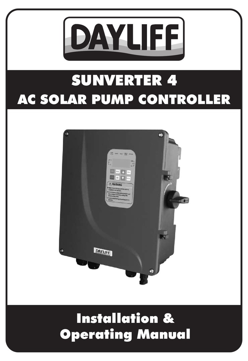
DAYLIFF SUNVERTER B Installation instructions

SUNVERTER B
AC SOLAR PUMP CONTROLLER
Installation &
Operating Manual

CONTROLLER SPECIFICATIONS
1.
1
2.
SYMBOLS & WARNINGS 3
INDEX
© Davis & Shirtliff Ltd 2022
Contents herein are not warranted
2.1 Purchase Inspection 3
2.2 Installation 3
2.3 Wiring 4
2.4 Operation 5
3. INSTALLATION & WIRING 7
2.5 Maintenance 6
3.2 Installation Method 7
3.1 Installation Instructions 7
2.6 Others 7
3.3 Installation Steps 8
3.4 Wiring Instructions 8
4. Operation & Control 16
4.2 Panel Operation Instruction 18
4.1 Panel Layout & Instruction 16
4.3 Initial Settings before First Operation 20
4.4 Function Parameters 21
3.5 Wiring Diagrams of Various Power Supply
9
3.5.1 Wiring Diagram for Solar Supply for Single Phase
10
3.5.2 Wiring Diagram for Solar Supply for Three Phase
Arrangements
Pump
10
Pump
3.5.3 Concurrent Connection of AC Mains Supply and Solar
10
Supply with Diode Module

6. MAINTENANCE
33
6.1 Routine Inspection & Maintenance 33
6.3 Mains Points of Inspection & Maintenance 34
6.2 Inspection & Maintenance Requirements 34
6.5 Storage 35
7. TERMS OF WARRANTY
36
6.4 Inspection & Replacement of the Damageable Parts 34
5. TROUBLE SHOOTING
30
5.1 Common Faults and Solutions 30
5.1.2 Tripping After Power or During Operation 31
5.1.1 No Display after Power On 31
5.1.3 The Pump Does Not Work 31
5.1.4 The Inverter Displays Fault Code 31

1
1. CONTROLLER SPECIFICATIONS
Dayliff SunVerter B is an AC/DC inverter specially designed for solar powering AC
motors in various water pumping applications and is suitable for retro fitting to existing AC
supply installations. It is enclosed in a plastic casing with IP20 protection grade suitable for
indoor installations or can be supplied with an additional enclosure for outdoor
applications. The unit is primarily designed for PV DC power input though it can be
connected to an alternative AC supply and manually switched. Particular features include.
ŸFully automatic operation, the inverter powers the pump to work from sunrise to
sunset.
ŸAdvanced MPPT (Maximum Power Point Tracking) capability providing fast
response, good stability and up to 99% efficiency
ŸProvides for pump soft start and full motor protection.
ŸConnections provided for high water level control and dry running protection using
float switches and well probes.
ŸUser friendly LED display interface with comprehensive display information.
ŸOptional automatic power supply switching function to support grid/generator
back-up to enable 24-hour operation.
ŸOptional remote monitoring and control capability using the unique iDayliff
Service.
CONTROLLER FUNCTIONALITY
ŸSettable minimum and maximum frequency and open circuit voltage.
ŸDisplay of operating parameters including frequency, voltage, amperage, input
power and pump speed.
Congratulations on selecting a Dayliff Sunverter B. They are
manufactured to the highest standards and if installed and operated
correctly will give many years of efcient and trouble free service. Careful
reading of this Installation Manual is therefore important, though should
there be any queries they should be referred to the equipment supplier.
Sunverter B
Water Tank
Solar Panel
Pump
Generator
Grid

2
ŸProtection against over and under voltage, over current, system overload and
module over temperature.
ŸFault detection with error code display.
INSTALLATION
Dayliff SunVerter B controllers are surface mounted and should be provided with an
enclosure for water and heat protection. Due to the high operating voltages proper
earthing is essential, which must be carried out by a qualified electrician.
As a rule all PV powered solar pumping systems should be provided with a PV solar
module array with a nominal output about 30% greater than the motor size. The arrays
should be wired in a combination of series and parallel connections to ensure that the
correct voltage is available into the inverter with appropriately sized PV Disconnect Circuit
Breaker and a Surge protector if applicable. It is important that the connection
arrangement is approved by the pump supplier. Connection to capacitor-less single
phase pumps should be done via appropriate capacitor box.
OPERATING CONDITIONS
0 0
Enclosure Class: IP20 Ambient Temperature: -10 C to +50 C
Relative Humidity: 0-95% Frequency: 0-60Hz
CONTROLLER DATA
Model
SVB/1.5M
SVB/2.2M
SVB/4M
SVB/4T
SVB/5.5T
SVB/7.5T
Motor
Rated
Power
(kW)
Rated
Voltage
(V)
Max
Input
Power
(kWp)
Output
Current
(A)
Max DC
Input
Voltage
(VDC)
Dimensions
(mm) Weight
(kg)
1.1 2.2 7
1.5 3.3 10
2.2 516
4 9.5
5.5 8 14
7.5 11 17.5
1x240 440 310-360
780 500-600
3x415
MP
Voltage
(VDC) H W D
186 126 155
285 165 200
285
230
165
140
200
172
4.6
4.6
1.7
2.7
DW
H

3
Do not install the inverter if there is water or water stains
inside.
DANGER
The installation work must be performed by qualied
electrical professionals, otherwise it may cause electric shock
or re.
DANGER
2.1 Purchase Inspection
2.2 Installation
DANGER
The inverter must be installed on metal or other ame
retardants and kept away from combustible materials,
otherwise it may cause re.
Do not install the inverter if it is damaged or with missing
parts, otherwise it may cause fault expansion or body
injuries.
DANGER
Do not touch the control terminals, PCB boards or other
components inside the inverter directly with wet objects or
body parts, otherwise it may cause electric shock.
DANGER
Do not install the inverter if it is inconsistent with the packing
list.
WARNING
Do not install the inverter if the specications on the product
nameplate are inconsistent with your order.
WARNING
2. SYMBOLS AND WARNINGS
Misuse will result in re, serious injury to persons or even
death.
WARNING
Incorrect use may cause mild or moderate body injuries and
damage to devices.
CAUTION

4
2.3 Wiring
The wiring work must be performed by qualied electrical
professionals, otherwise it may cause electric shock or
damage to devices.
DANGER
The wiring work must be carried out strictly according to this
manual, otherwise it may cause electric shock or damage to
devices.
DANGER
All power supplies connected to the inverter must be cut off
and wait for not less than the time indicated on the inverter
before wiring work, otherwise it may cause electric shock.
DANGER
WARNING
Handle the device gently to prevent accidental fall off, which
may hurt the feet and break the inverter.
WARNING
Install the inverter in the place where there is no vibration, no
w a t e r d r o p l e t s a n d n o d i r e c t s u n l i g h t .
WARNING
If the inverters are to be installed in the cabinet, especially
two or more inverters in one cabinet, please pay attention to
the installation position, ensure good ventilation and heat
dissipation, otherwise it may cause device fault or damage.
WARNING
Do not drop the wire end, screws or drilling residue into the
inverter during the installation, otherwise it may damage the
device.
DANGER
Assemble and tighten the xing screws of the inverter
according to the regulations, otherwise the inverter may
accidently fall off and get damaged.
DANGER
It is not allowed to install the inverter in environment
containing explosive gas, otherwise it may cause explosion.
DANGER
It is not allowed to install the inverter in place accessible to
children and other public, otherwise it may cause electric
shock.

5
Shielded cables must be used for encoders, sensors and other
suscep t i b l e com p o n e n t s a n d relia b l y ground e d .
WARNING
Cables, circuit breakers, contactors and other components
must be selected as required by the manual.
WARNING
Strictly follow the screen printing on the inverter during the
wiring and do not connect the input and the output inversely,
otherwise it can damage the device.
WARNING
2.4 Operation
Make sure all the wiring and connections are correct and the
case cover is close before powering on.
DANGER
Do not install compensation capacitors or surge suppressors
at the output of the inverter, otherwise it may cause overheat
and damage the inverter.
WARNING
Do not remove cover plate after powering on, otherwise it
may cause electric shock.
DANGER
Do not perform any operation other than the panel setting on
the inverter during running, otherwise it may cause electric
shock or damage the device.
DANGER
The inverter must be grounded reliably, otherwise it may
cause electric shock.
DANGER
The terminal signal cable of the inverter should be put away
from the power cable as far as possible. If the distance is not
enough, they should be cross-distributed vertically,
otherwise it will cause signal interference.
WARNING
Make sure all terminal screws are tightened while wiring,
otherwise it may damage the device.
WARNING

46
Do not change the parameters of the inverter arbitrarily,
otherwise it may damage the inverter.
WARNING
2.5 Maintenance
The maintenance work must be performed by qualied
electrical professionals, otherwise it may cause electric shock
or damage to devices.
DANGER
All power supplies connected to the inverter must be cut off
and wait for not less than the time indicated on the inverter
before wiring work, otherwise it may cause electric shock.
DANGER
Take anti-static measures and prevent foreign matter from
entering the inverter.
WARNING
Do not conduct insulation and withstand voltage tests on the
inverter, and do not use a megohm to test the control circuit of
the inverter.
WARNING
Tighten the screw with sufcient torque.
WARNING
Keep the inverter and components away from inammable
materials.
WARNING
Do not touch the fan or radiator base, otherwise it may cause
mechanical injuries or burns.
DANGER
Do not frequently turn on and turn off the inverter input
power, otherwise it may damage the inverter.
WARNING
The inverter must be in no output state when the circuit
breaker or contactor at the output of the inverter is switched
on or off, otherwise it may damage the inverter.
WARNING

47
Ambient Humidity 5 ~ 90% (No dew condensation).
Environmental Factor Requirements
Ambient Temperature
0 0
-10 C~ +50 C;
0
The rated output current should be derated by 2% for every 1 C
0
increase when temperature is over 40 C; When operating in a
small enclosed space such as a cabinet, please strengthen the
cooling to avoid the internal temperature exceeding the
ambient temperature requirements.
Storage Temperature 0 0
-40 C ~ +70 C.
Vibration Less than 0.5 g.
Altitude
0 ~ 2000 m;
The rated output current should be derated by 1% for every
100 m increase when altitude is over 1000 m.
Installation Site
Indoor use, for outdoor use, protective measures must be
taken;
Install the inverter on flame retardant surface with sufficient
heat dissipation space and good ventilation;
Keep away from electromagnetic radiation sources; No
flammable, explosive, corrosive gases; no radioactive
substances, no flammable substances; no dust, oil mist,
steam;
No direct sunlight
3.2 Installation Method
To ensure good heat dissipation of the product, please install
it vertically. Do not install it horizontally or transversely.
NOTE
2.6 Others
At the end of its design life, the inverter should be disposed
as industrial waste. During incineration, the electrolytic
capacitor may explode and some parts may produce toxic
and harmful gases.
WARNING
3. INSTALLATION AND WIRING
3.1 Installation Instructions
Installation of the inverter according to the installation
environment requirements is the precondition for ensuring
long-term normal and stable operation of the inverter.
NOTE

48
Inverter Rated Power Installation Space Dimensions (mm)
A B
>37kW
≥50
≥80
≥200
≥300
ŸIf multiple inverters are to be installed in the same cabinet, it is recommended to
adopt transverse side-by-side installation. If two inverters are to be installed
longitudinally, a guide plate should be added in the middle.
3.3 Installation Steps
Step 1 : Mark the mounting hole positions on the mounting wall according to the
layout and dimension diagrams.
Step 2: Fix the screws (bolts) to the marked positions.
Step 3: Hang the inverter to the screw (bolt).
Step 4: Tighten the screws (bolts) and fix the inverter to complete the installation.
3.4 Wiring Instructions
Ÿ Before wiring, please open the inverter top cover first as shown in Fig. 2.
Fig 1: Installation Direction and Space Requirements
37kW
≥

49
Fig 2: Sunverter B Open Cover Diagram
Models 2.2kW Models 4-11kW
Models>11kW
3.5 Wiring Diagrams of Various Power Supply Arrangements
3.5.1 Wiring Diagrams for Solar Supply for Single Phase Pump

410
3.5.2 Wiring diagram for Solar Supply for Three Phase Pump
3.5.3 Concurrent connection of AC Mains Supply and Solar Supply
with Diode Module
Without the DIODE module, only one power supply can
be connected at a time i.e. AC mains or PV solar.
NOTE

411
PV+/PV- PV array input terminals
PV Input
Terminal Mark Name Function
R/S/T
3-phase 4-wire AC power neutral
terminal for AC power supply automatic
switching mode only
AC Input for SVB/T three
p h a s e m o d e l s a n d
SVB/4M single phase
model.
3PH/380V-415V AC power input
terminals. Any two terminals for
1PH/220V-240VAC power input for
SVB/4M single phase model.
N
L/N 1PH AC power input terminals
U/V/W
Inverter 3PH AC output terminals,
connected with the pump. For single
phase models, inverter U/V terminals
connected to L-N terminals in the pump
terminal box with capacitor(s) or
capacitor control box
3PH AC Output
1PH AC Output for all
SVB/ M si ngle p hase
Ground terminal, ensures the terminal
is securely connected to the safe earth
Safety Ground Earth
Terminal (PE)
Well water level signal terminals, closed
means the water level is normal
Well Water Level
WELL/COM
Tank water level signal terminals, closed
means the water level is normal
Tank Water Level
TANK/COM
In order to ensure the safe and reliable operation of the
entire solar pumping system, please make sure that the cable
diameter and quality meet the system requirements (refer to
Pg 15 for cable requirements).
WARNING
AC Input for SVB/1.5M
and SVB/2.2M models.

412
Ÿ The basic wiring of Sunverter B is shown in Fig.3
Fig 3: Standard Wiring Diagram
Control Terminal Description
PE 485+ 485- 0~10V/5V AIN GND COM D13
+24V PW COM DI1 DI2 COM D14 D15 T1A T1B T1C T2A T2C
Control Board Terminal Function Description
+24 V
24V + 10%, isolated from GND
internally
Maximum output current: 200 mA
Type Terminal
Label Function Description Technical Specications
S w i t c h
Signal Input
Terminal
+24 V power supply
PW Connected to +24 V terminal by
default
External power input terminal
(power supply of switch signal
input terminal)
PV
Disconnect
Sunverter B
Solar Pumping
Inverter
Note: For Single Phase
m o d e l s U & V
terminals of inverter
should be connected
to L&N terminals of
single phase pump
with capacitors or via
capacitor control box.

413
DI1~DI5
Input specification: 24 V, 5 mA
DI1: Operation control signal,
valid when connected to COM
(connected by default)
DI2: Tank full signal, valid when
connected to COM (disconnected
by default)
DI3: Source low signal, valid
w h e n c o n n e c t e d t o C O M
(connected by default)
DI4: MPPT disable signal, disable
MPPT function by connecting DI4
to COM and set target frequency
to rated frequency (disconnected
by default); can be used as
AC/DC power switching trigger
signal (modify corresponding bit
in parameter F05.10 to 1)
DI5:Reserved
Type Terminal
Label Function Description Technical Specications
S w i t c h
Signal Input
Terminal
Switch signal input terminal 1 ~5
COM Isolated from GND internally
Common ground terminal of
switch signal, +24 V or external
power supply
+10V
Output current: 0~50 mA (If a
potentiometer is connected
between +10 V and GND, the
resistance should not be less than
2 kΩ)
+10 V power supply for AIN
AIN
The input signal can be selected
as voltage or current by modifying
the internal jumpers.
Input voltage: 0 ~ 10 V/0 ~ 5 V
(0 ~ 5 V by default), modify the
internal jumpers to select range;
can be used as solar voltage
measurement input of Boost
module (modify parameter
F15.16 to 1)
Input current: 0 ~ 20 mA
Analog signal input terminal
GND
Common ground terminal of
analog signal and +10 V power
supply
Isolated from COM internally

414
NOTE
The analog signal cables and digital signal cables should be
separated and not entangled.
T1A/T1B/T
1C
T1A-T1B: normally close (AC
contactor coil control contacts in
AC/DC power switching function)
T1A-T1C: normally open Contact
capacity: AC 250 V/3 A, DC 30
V/1 A
Type Terminal
Label Function Description Technical Specications
R e l a y
Output
T e r m i n a l
Relay output 1
485+/485 RS485 communication interface,
adopt Modbus protocol
R S 4 8 5 c o m m u n i c a t i o n
T2A/ T2C
T 2 A -T 2 C : n o r m a l l y o p e n
Contact capacity: AC 250 V/3 A,
DC 30 V/1 A
Relay output 2
C o m m u n i
c a t i o n
T e r m i n a l
Main Circuit Terminal Description
SVB/M (≤ 2.2 kW)
SVB/4M, SVB/T (>2.2-22 kW)
SVB/30T, SVB/37T
SVB/45T, SVB/55T

415
Main Circuit Terminal Function Description
R, S, T
(L, N)
Three-phase (single-phase) power supply input terminal. For
SVB/4M, any two terminals (R,S,T) can be used to connect single
phase supply
Terminal Screen
Printing Name Function Description
(+), (-) Positive and negative terminal of the solar array
U, V, W Three-phase AC output terminal, connected to pump motor
U, V, W U and V terminals used for single phase AC output. Terminals
connected to single phase pump motor with capacitor (s).
Safety protection earth terminal (PE), please ensure reliable
grounding
P1, PB Spare terminal, please do NOT connect them
Cable Sizing
Model
2
DC Cable (mm ) 2
AC Cable (mm )
SVB/7.5T
Contact D&S dealer for sizing cables for larger sizes of SVB models
SVB/4M
SVB/5.5T
SVB/4T
SVB/1.5M
SVB/2.2M
(+)/(-) L/N R/S/T, U/V/W
2
Earth Cable (mm )
PE
Signal Cable
2
(mm )
4
6
4
2.5
2.5
4
-
2.5
4
4
6
4
2.5
2.5
4
1.5
2.5
2.5
2.5
2.5
1.5
1.5
-
NOTE
The recommended cable should be used under the
conditions of ambient temperature (≤ 40℃), cable length (≤
100 m) and working current (≤ rated current).
SVB/75T-SVB/110T

416
Other Notes
Ÿ A DC circuit breaker must be installed as protection switch for solar DC input.
Ÿ The inverter only has one pair of DC input terminals. If the solar modules are
multi-paralleled, an additional solar combiner box is necessary.
ŸThe inverter must be grounded reliably and the grounding cable should be as
thick and short as possible. If possible, the inverter should be grounded
separately.
ŸIn areas with high incidence of lightning, please install an external surge
suppressor at the power input of the inverter.
ŸIf the inverter is far from the motor (>200 m), it is recommended to install an
output reactor.
ŸIt is recommended to install input and output reactors, dedicated filters and
magnetic rings at the input and output of the inverter, which can effectively
reduce the noise and avoid disturbing other components.
4. OPERATION AND CONTROL
4.1 Panel Layout and Instruction
The inverter operation panel is composed of four parts as shown in the figure below:
state indicator lights, unit indicator lights, 5-digit LED display and operation keys
Fig 4: Operation Panel Layout

4
17
Panel
Label Name Description
HZ Unit of current display parameter is Hz Frequency Indicator Light
V Unit of current display parameter is V Voltage Indicator Light
A Unit of current display parameter is A Current Indicator Light
% Unit of current display parameter is percentage Percentage Indicator Light
RPM Unit of current display parameter is RPM Rotation Speed Indicator Light
kW Unit of current display parameter is kW Power Indicator Light
3
m /h 3
Unit of current display parameter is m /hWater Flow Rate Indicator Light
Unit Indicator Lights
Panel
Label Name Description
RUN/
STOP
Light on: Operating
Light off: Stop
Light blink: Start-up countdown
Operation State Indicator Light
State Indicator Lights
PV/AC Light on: Solar Power Supply
Light off: AC Power Supply
Note: This indicator light is used in AC/DC power
switching function
Power Supply Indicator Light
RMT/
LOC
Light on: Communication Control Mode
Light off: Operation Panel Control Mode
Light Blink: Terminal Control Mode
Run/ Stop Control Mode Indicator
Light
ALERT Light on: Fault Alert
Light off: No Fault
Light Blink: Overload Warning
Alert Indicator Light
5-digit LED display can show various monitoring data such as setting frequency and
output frequency, as well as function codes, parameter values and alert codes.
5-Digit LED Display
This manual suits for next models
6
Table of contents
Other DAYLIFF Controllers manuals
Popular Controllers manuals by other brands
Armstrong
Armstrong 3750 Installation and operating instructions
Palazzetti
Palazzetti EASYTOUCH USE AND FUNCTION

CLINTON INDUSTRIES
CLINTON INDUSTRIES 1190E manual

Renishaw
Renishaw UCC T3-2 installation guide

Balboa Instruments
Balboa Instruments ML900 Installation instruction
EuroLite
EuroLite DMX OPERATOR 240 user manual
Stamford
Stamford AS440 Specification, Installation and Adjustments
Hubbell
Hubbell Electric Fire Pump Controllers LXi 2200 Specifications
AS Torantriebe
AS Torantriebe R50 24V Operating and installation instructions

Gigarise
Gigarise SE2000 SERIES instruction manual
LS ELECTRIC
LS ELECTRIC XGL-EIPT installation guide

LEGRAND
LEGRAND 784 28 quick start guide
