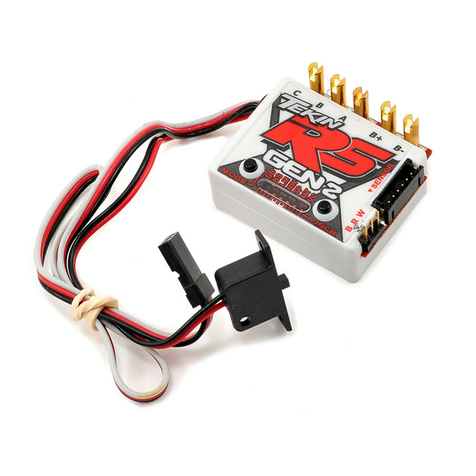
Tekin B1 User manual

NOTE: Before Radio Cali brating, e nsure speed control is
hoo ked up to the receiver, a c harged battery is properly con-
nected, and the transmitter is turned on. On your radio, set all
trim adjustments to the middle, throttle/brake EPAs set to max
and ensure that your throttle directio n is set to “normal” .
Calibration is really very simple, you just press and ho ld the
MODE button for 3 seconds to e nter radio calibrate, let the
speed control “find” your neutral, then let it “find” your full
throttle and full brake. If you are unsure how t o pe rform this
procedure, follow the detailed steps outlined below.
Congratulations on your purchase of the B1/B1-R, Tekin’s
High P erformance Mini Brushed Motor Electronic Speed Con-
trol. The QuickTunefeature allows the user t o quickly and
accurately adjust all critical operating parameters. Just connect
the speed control as described below, perform a quick radio
cal ibrate, and yo u are re ady to race!
B1
Forward / Brake
PROFESSIONAL MINI B RUSHED SPEED CONTROL
•Adjus table Drag Brake /Reverse Type
•Voltage Cutoff for LiPo Cells
•Push ( Anti-Drag Braking )
•QuickTuneDigital Setup
•Tempe rature Monitor
OWNER’S MANUAL
INTRODUCTION
The following statements ne ed to be understood before usi ng
the B1/B1-R:
1. Turn on the transmitter first to avoid uncontrollable noise
to speed control.
2. Dis connect battery from speed control when not in use.
3. Do no t hoo k-up the battery backwards! No reverse volt-
age protection.
4. Do no t operate speed control in or aro und water.
5. Insulate exposed wires with heat shrink tubing to prevent
short circuits.
6. The B1/B1R is intended for Mini vehicles only.
SOLDERING
IMP ORTANT: Use extreme care and observe proper safety
pre caut ions whe n s ol der ing. Al ways wear eye pr otec tion. Be
sure that both wires are disconnected from the battery before
soldering on the posts.
Never keep a hot solderi ng iron on the speed control solder
posts for more than 3 seconds—the sol der post may be come
de-soldered from the speed control and become damaged.
HINT: It should only take a few seconds to solder the wire to
the post. If you do not complete the solder joint in approxi-
mately 3 seconds, remove the iron, clean and tin the tip, then
repeat the procedure below. Applying a small amount of solder
paste flux can often help sol der flow on a stubborn surface.
SOLDERING CONT...
ATTACHING WIRES TO THE SPEED CONTROL:
1) Red Wires are usually used to connect the speed control
to the positive battery terminal and the positive motor
terminal. Black wire is typically us ed for the battery
negative t erminal, and blue is used for the ne gative motor
connection. Inspect the sticker on the speed controlor
refer to the diagrams to determine which color wire to
attach to each post.
2) Strip back the insulation of the wire by about 3/32” to
1/8” and “pre-tin” the wire by heating the end and apply-
ing solder until it is thoroughly covere d. You may shake
of any excess solder while it is still hot. Be very careful
not to splash yourself with hot solder.
3) If there is no solder on the post, place the tip of the iron in
the notch on top of the po st and apply a small amount of
solder to the post. When the solder has flowed, remove
the soldering iron, wipe the tip clean and apply a small
amount of fresh solder to it.
4) Hold the wire so t he tinned end is in co ntact with the
notch of the post. Now touch the iron tip to the wire and
the post. Wait about 2 seconds for the solder to flow, and
then remove the iron while still holding the wire. You
may le t go of the wire after a seco nd or two when the
solder sets.
For B 1 Co nnectio n Diagra m, Re fer to F igure 2 ,
For B1R Connection Diagram, Use Figure 3.
1) Placement: Choose a l ocation for the speed control that is
protected from debris. HINT: To prevent radio interfer-
ence place the speed control as far away from the radio
receiver as possible and keep the power wires as short as
possible. If possible plan on routing power and motor
wires away from the radio receiver and radio wires.
2) Mounting: For best results clean the bottom of the spee d
co ntrol and chassis. Using the doubled-sided tape,
(included) mount the speed control to chassis.
3) Using a small piece of double-sided tape, mount the ON/
OFF switch in a convenient place.
4) Determine how you would prefer to connect the motor
and battery pack to the speed co ntrol. Using connector
pairs is preferable for most applications as it allows you
to easi ly switch battery packs and change motors.
Whether using connec tors or direct soldering, consider
where yo ur battery pack sits and how much wire will be
needed to attach to the speed control.
HOOKUP INSTRUCTIONS
HOOKUP INSTRUCTIONS CONT...
NOTE: Make sure all wires are secure and a safe distance
from all moving parts—use the zip-ties in the accessory pack.
RADIO CALIBRATION
QuickTuneMODES
MODE RANGE DEFAULT
DRAG BRAKE
(DRG B) 1-11 1 (OFF)
NEUTRAL WIDTH
(NW) 1-11 5
CU R REN T L I MI TE R
(LIM) 1-11 11 (OFF)
PUSH CONTROL (ANTI DRAG)
(PC) 1-11 1 (OFF)
REVERSE TYPE—-B1R
(RT)
THROTTLE PROFILES-B1
(TP)
1-3
1-6
3
3
VO L TA GE C U TO FF
(VC) 1-4 1 (NONE)
PRECAUTIONS
DO NOT CONNECT BATTERY INCORR ECTLY TO
SPEED CONTROL, VERIFY THAT THE B ATTERY
POSITIVE WIRE WILL CONNECT TO THE SPEED
CONTROL POSITIVE WIRE BEFORE CONNECTING!
1) CONNECT SPEED CONTROL TO RECEIVER
Plug the speed control into the throttle channel of the receiver.
• Channel 1: Servo
• Channel 2: Speed Control
“REMEMBER: 1 to Turn, 2 to Burn”
3) CONNECT SPEED CONTROL TO MOTOR
Visually verify that the connector on the motor and the speed
control match the chart below, then connect.
Startup Sequence
When the power switch is turned ON the speed c ontrol begins
looking for the neutral signal. If a neutral signal is found the
Arming Sequence (flashes LEDs/chime) will occur followed by
LED3 on s teady. NOTE: If Arming Sequence does not occur
see Trouble Sho oting section of this manual before proceeding.
One Touch Radi o Cali bration
1) Turn on transmitter.
2) Turn on speed control.
3) Press and ho ld the MODE butto n on the speed co ntro l for
3 seconds. All LEDs will blink red 3 times with 3 chimes.
The speed control will make a pulsing chime as it loo ks
for a neutral signal—you do not need to do anything yet.
4) When NEUTRAL position is found and recor ded, LED3
will flash and a confirmation chime will sound .
5) The pulsing chime will begin again and LED6 will flash;
pull transmitter trigger to the full thro ttle positio n and
hold until t he confirmation chime sounds.
6) The pulsing chime will begin again and LED1 will flash;
push transmitter trigger to the full brake position and hold
until the confirmation chime sounds.
7) Release trigger to return to neutral position. LEDs will
flash and the arming sequence chime will sound.
8) LED3 is now on steady. Calibration is complete and you
are ready to dr ive!
NOTE: If any problems occur, repeat radio calibration.
HINT: Once calibrated, the LEDs on the speed control will
advanc e as the throttle or brake is applied.
Hairpin Trigger Response: If you wish to have a very short
trigger range, then only squee ze the thro ttle/brake trigger
partially during the radio calibration proce dure. Throttle/Brake
response will not be quite as s mooth, but yo u can pull full
throttle very quickly.
QuickTune:
1) Press the MODE button to access the desired setup mode.
The LED starts blinking to indicate that mode selection is
under way. Each time the MODE button is pressed and
released, the LED advances. For example, to get to the
Voltage Cutoff adjustment, simply press and release the
MODE button 6 times. NOTE: Do not wait longer than
5 seconds to adjust the selected MODE or the speed con-
trol will return to normal operation.
2) Press and release the INCR button to adjust the value.
The first time INCR button is pressed, the LED(s) will
display the existing setting. Each time the INCR button is
pressed the value will advance, then after maximum, start
over again at the lowend of the scale. If two LEDs are
on at once, it indicates a value mid-way between the
LEDs.
QuickTune Exampl e: Le t’s say you want to us e a 2 cell LiPo
battery. To change the Voltage Cutoff from the default setting
(1 = None) to setting 2 (2 = 6.0 Volt Cutoff), first followstep 1
above by pre ssing and re leasing the MODE butto n 6 times.
Nowpress and releasethe INC button, the LED should show
the current setting of 1. Press and release the INC button again
and the LED will move to position 2, indicating that Voltage
Cutoff is now set to 6.0 Volts. Wait 5 seconds and the ESC
returns to normal operation.
HINT: If you wish to s et another Program Feature, press the
MODE but to n again. After 5 seco nds paus e, the values you
selected will be saved in memory and the speed control will
res ume normal o peration.
P IT TUN IN G : If you are in the pit area and cannot use your
transmitter you may use pit tuning mode to adjus t settings by
following this pro cedure: Unplug the steering servo from the
receiver to avoid servo damage. Hold down either MODE or
INCR button while turning the power switch on. An LED se-
quence will occur indic ating you are in pit tune mode. The
user settings will be active, but the motor will no t run and the
speed control will not respond to receiver signals. Turn the
speed control po wer off and back on to resume nor mal opera-
tion.
LED1: DRAG BRAKE control provides immediate braking
action i n the neutral zone. This gently slows the car down
when yo u let off the trigger. Drag Brake can pro vide a better
cornering approach . Higher values increase the degree of drag
braking.
QuickTune
Tekin’s QuickTuneelectronic setup feature allows users to
change every criticaloperating parameter in a quick, easy, and
accurate fashion. The basic operat ion is describe d as:
•Use MODE button to sc roll to a Program Feature.
•Use INCR (increment) button t o vie w/adjust the Feature.
The B1 series has a built-in self-test mode that checks all major
sys tems on the speed control. Before using the se lf-test mode,
be sure the re ar wheels are free to spin (off the ground). To
activate the self-test, turn the speed control on, then press and
hol d both MODE and INCR butto ns simultaneousl y for 5
sec onds. After 5 seconds, the LEDs will ramp up in sets of
two. Circuits inside the speed control are tested to see if any
problems have o ccurred. If the unit passes self-test, t hen LED3
will s t ay o n s teady.
If probl ems occ ur turn the power off to the unit and verify all
ot her connections are clean/tight/correct (motor, receiver, bat-
tery, plugs, etc). After verification, power the unit back on.
NOTE: Activating the self-test mode also resets all the user-
programmable settings and parameters to their default values.
The user’s radio calibration settings are also reset to defaults.
SELF TEST
B1-R
Forward / Brake /
Reverse
ESC MOTOR
(M -) Blue Wire (-) Negative
(M +) Red Wire (+) Positive
2) CONNECT SPEED CONTROL TO BATTERY
Visually verify that the connector on the battery pack and the
speed control match the chart below., then connect.
DANGER: If the battery wires touch during the plug installa-
tion. It will cause an electrical short circuit resulting in damage
to the pack and possibly a fire hazard. Tekin reco mmends the
use of high quality battery connectors, such as Dean’s P lugs, to
improve po wer transfer and minimize the risk of short-circuits.
ESC BATTERY
(B-) Black Wire (-) Negative
(B +) Red Wire (+) Positive
Pit Tune Mode
SPEED CONTROL SPECIFICATIONS
Controls, B1 Fwd/Br k
Input Power (Cells)
4-8 NiCd/NiMh
2-3S LiPo
Motor Limit Si ze 370 Size or smaller
Motor Limit Turns None
ON Resistance
B1
B1-R
0.0013 Ohms
0.0052 Ohms
Max Current
B1
B1-R
60 Amps
30 Amps
BEC 5 Volts,1.5 Amps
Power Wires 16 GASilicone
Dimensions 1.0 x 0.9 x 0.25 In.
(25.4 x 23 x 6 .3 mm)
Weight (with wires) 0.28 Oz (8g)
Controls, B1-R Fwd/Br k/Rev
The following items are neede d to co nnect your s peed control:
•Soldering Iron
•60/40 Electric Grade Solder (or silver solder)
•4 pieces 16 Ga. Wire (Included)
•Motor/Battery co nnectors (2 pair)
MOUNTING
SOLDERING, TOOLS NEEDED
SOLDERING CONT...
ATTACHING WIRES TO THE BATTERY:
The same techniques described i n the preceding sec tion may be
used to solder the wires to the battery connectors.
IMP ORTANT: Take precautions if removing factory battery
co nnectors. Connecting the battery backwards will cause dam-
age, an d will void warranty. When soldering connect ors to a
battery pack, cut only one wire ofthe battery pack at a time to
ensure that the e xposed wires cannot short to gether.
HINT: If you are using Dean’s c onnectors for both the batter y
and the moto r, make sure that you have a male and a f emale
attache d to the speed control wires. That way, you canno t acci-
dentally connect the battery to the motor wires or vice versa.
1) If using a connector betwee n battery and speed control
make sure that the ends will be mated together correctly,
male to female, and that the wire colors match—red to
red and black to black.
2) Solder the wires from the speed control to each of the
connectors, then solder wires from the battery to each
connector’s mate.
ATTACHING WIRES TO THE MOTOR:
The same techniques described in section 5 may be used to
solder the wires to the motor.
1) If using a c onnector between motor and speed control
make sure that the ends will be mated together correctly,
male to female, and that the wire colors match—red to
red and blue to blue.
2) Solder the wires from the speed control to each of the
connectors, then solder wires from the motor to each
connector’s mate.
REMOVING WIRES:
1) Have a hot iro n and the speed co ntrol secured. Clean the
tip of the i ron and apply a small amount o f solder. While
the tip is still smoking from the flux in the solder, touch
the tip of the iron to the top of the post.
2) As the solder on the po st melts, pull on the wire yo u wish
to remove.
HINT: If there is excess solder remaining on the post, you
may remove it by heating the po st until the solder just starts to
melt, then quickly tapping the speed control against the
workbench to knock off the excess sol der.
SOLDERING CONT...

Listed below are a number of tips to ensure that you will get
year s of trouble-free performance from your Tekin speed
control.
LED2: NEUTRAL WIDTH adjusts your deadband around
the neutral point. A low ne utral width value pro vides more
sensitive trigger re sponse around neutral.
LED3: CURRENT LIMITER adjusts the throttle response
during acceleration to control annoying wheelspin. Low values
allow low amounts of current to pass to the motor, higher val-
ues allow higher amounts of current. The top value (11) turns
OFF current limit.
LED4: PUSH CONTROL or ANTI-DRAG BRAKING
overcomes the natural drag of the motor when you return to
neutral. Racers refer to this as “creep” , this setting eliminates
the need to trim the throttle forward to create a coasting
(pushing) effect. Lo w values give you a shor t duratio n push,
higher values a longer duration push
LED5: BRAKE/REVERSE TYPE **B1R ONLY**
1) Proportional Brake with Reverse Lockout (LED1 ON).
Proportional brake will be applied during reverse throttle.
2) Forward to Brake to Reverse (LED1-2 ON). The car will
operate freely in forward and reverse. (Brakes to a stop
before switching into reverse)..
3) Proportional Brake with Reverse Delay (LED1-3 ON).
The car will only go in reverse if the trigger has been in
neutral for 1 second, otherwise it operates like
proportional brake with no reverse.
NO LIGHTS COME ON
Check for de ad batteries . Check the connections between the
batteries and the speed controller and that the switch is in the
“ON” position. Verify that there are no bad connections at the
speed controlle r. Check for reverse battery connection.
ALL LE Ds F L ASH IN G
No r adio signal can be f ound. Check rece iver connection and
verify that ESC is plugged into correct channel. Verify trans-
mitter and r eceiver are functioning properly.
BOTTOM OR TOP 3 LEDs FLASHING
Radio signal found, but neutral point from transmitter is out of
expected range. Speed control not calibrated properly or radio
setti ngs have been changed. Recalibrate speed co ntrol as de-
scribe d in the Radio Calibr ation section.
ADJUSTMENT MODES CONT...
Before sending your B1/B1-R in for service, please review the
Instruc tions and Troubleshoo ting sections. After reviewing
these instructio ns, if your speed co ntrol still requir es service,
please contact our customer service department for additional
assistance. To obtain the most current product service options
and pricing, consult the following:
WEBSITE: (www.teamtekin.com) Follow the instructions
from the Service Request section of our website.
PHONE/FAX: Contact our customer service department.
WARRANTY SERVICE: For warranty work, you MUST
CLAIM W ARRANTY on A COMPLETELY FILLED OUT
PRODUCT SERVICE FORM and include a VALID CASH
REGISTER RECEIP T with purchas e date, dealer name &
phone # on it, or an invoice from previous service. If warranty
provisions have been voided, there will be service charges.
NOTE: Hobby dealers or distributors are not authorized to
replace TEKIN products thought to be defective.
Tekin, Inc.
McCall, Idaho
(20 8) 634-5559 / (208) 634-5569 (FAX)
www.te amtekin.c om
WARRANTY
TEKIN, INC. guarantees speed controllers to be free from fac-
tory defects in materials and workmanship for a period of 120
days from date of purchase, when verified by sales re-
ceipt. This warranty does not cover: suitabilit y for specific
application, co mponents worn by use o r improper voltage,
tampe ring, misuse, or shipping. Our warranty liabili ty shall be
limited to repairing unit to our original specifications. Because
we have no control over the installati on or use of this product,
in no case shall we be liable for damages.
Additionally, these items void the warranty:
1) Using the same polarity connectors on the battery and
motor wires from the speed controller.
2) Allowing water or moisture into the speed controller.
3) Incorrect wiring.
4) Use inconsistent with the instructions.
OPERATING TIPS
LED5: THROTTLE PROFILES **B1 ONLY**
1) Mildest profile, concave (LED1 ON)
2) Mild profile, concave (LED1 -LED2 ON)
3) Linear profile (LED1-LED3 ON)
4) Aggressive profile convex (LED1-LED4 ON)
5) More aggressive profile, convex (LED1-LED5 ON)
6) Custom— User Adjustable Using Tekin HotWire PC
Connection (LED1-LED6 ON).
LED6: VOLTAGE CUTOFF
1) NONE (LED1 ON)
NiCd/NiMh Cells.
2) 6 Volts (LED1-LED2 ON)
2 Cells LiPo (2S)
3) 9 Volts (LED1-LED3 ON)
3 Cells LiPo (3S)
4) Custom (LED1-LED4 ON)
User Adjus table Cutoff, requires Tekin HotWire PC
Connection.
IMPORTANT: If using Lithium Polymer (LiPo) batteries, DO
NOT operate your vehicle with the factory default Cutoff Volt-
age setting (None).
PROPER ON/OFF PROCEDURE
Always turn your transmitter on first and then turn on your
speed control. At the c onclusion o f your run, simply reverse
the above procedure.
BATTERY P OLARITY
It is extremely impor tant to e nsure the battery pack is
co nnected to t he speed control properly. Co nnecting the m
back wards could cause severe damage to the battery pack and/
or speed control.
DO NOT JAM THROTTLE
This will cause tremendous reduction in run time and excessive
heat build-up.
RADIO INTERFERENCE
Try to keep the r eceiver at l east 1-2 inc hes away from any mo-
tor or battery wires.
RECEIVER BATTERY
The built-in BEC (Battery Eliminator Circuit) is stro ng enough
for 1 standard se rvo. If you are using a high po wer ser vo you
may need a separate receiver battery (see Receiver Battery
section).
NO REVERSE
QuickTune mode, Brake/Re verse Type is set to o ptio n 1.
QuickTune mode, Brake/Re verse Type is set to o ptio n 3
(transmitter trigger must be in neutral position for 1 s econd
before reverse is enabled). Speed control is a B1, not a B1R
(not a reversing type).
MOTOR WILL NOT SHUT OFF OR RUNS SLOWLY
Inco rrect radio calibration or throttle trim setting on transmit-
te r. Check transmitter se ttings and rec alibrate s peed control.
Moisture in speed control: Unhook batteries and le t the s peed
co ntrol dry.
MOTOR CUT OUT/RADIO INTERFERENCE /POOR
RANGE
Transmitte r batteries are low o r damaged. Mismatched c rys-
tals. The three-wire cable from speed control to receiver may
also be too long; 6 inches is the maximum. This speed control
radiate s very low noise and you shoul d have no trouble with
interference. If you do have interference , mount the speed
control in the pan, and mount the receiver andantenna at the
top of the shock tower. Try to keep the receiver away from the
batteries, power wires, metal or graphite.
TROUBLESHOOTING
NOTE: Optional. Connect a separate battery pack to the
receiver using the “B” or “BAT” socket on your receiver. A
small switch should be used on the receiver pack to operate the
radio., and the receiver pack should have no more than 5 cells.
IMPORTANT: You must remove the red wire from the speed
co ntrol servo plug and cover it with heat shrink tubing.
The On-Board Temperature Monitor wor ks to provide you with
important feedback on speed control temper ature, he lping you
to adjust gearing and avoi d long term heat damage. To use;
1) The spe ed control must be calibrated to yo ur radio and
the r adio must be in the neutral po sit ion.
2) The middl e LED will be on steady, and should blink out
ever y 2 seconds.
3) At the moment that the center LED blinks out,one or
more of the other LEDs will light up.
4) LEDs 1-3 lit is typical of light loads or a stoc k motor.
LEDs 1-5 lit indicates heavy loads and is typical when
running mod moto rs. LEDs 1-6 lit indicates high internal
temperatures approaching thermal shutdo wn. Dis con-
tinue use until the speed co ntrol returns to normal o perat-
ing temperature.
SERVO WORKS, THROTTLE DEAD
Spee d control not adj usted correctly. May be in Pit Tune
mode. If LEDs are flickering, may indicate that Voltage Cutoff
is set above battery pack voltage. Check that cutoff is cor-
rec tly set and that batte ry is fully charge d. Motor or connec-
tions to motor are bad. Receiver plugor connections are bad.
Spee d control not plugged into throttle channel o n receiver.
STUTTERING UNDER HEAVY ACCELERATION
Receiver is getting magnetic field interference. Try mounting
receiver on its side and/or spacing it 3/16 inch up from the
chas sis. If t his does not work, try mounting it on its other side.
Move power wires away from receiver. Check for low current
limiter setting. Check for incorrect Voltage Cutoff setting.
BRAKES DO NOT WORK AT ALL
Speed control or radio transmitter improperly adjusted. Adjust
EPAs on transmitter all the way out and recalibrate speed con-
trol to radio.
AU TO CO UN T N O T W O RK IN G
Mount transponder at front of c ar away from batteries and
wires.
SERVO AND THROTTLE DEAD
Check for dead batt eries, bad co nnections to s peed cont rol,
dad receiver plug co nnection. Switch may need replac ing.
Bro ken wires, bad crystal, bad radio equipment.
THROTTLE WORKS, SERVO DEAD
Bro ken servo. Wiring of plug is bad or incorrectly wired.
TEMPERATUREE MONITOR
TROUBLESHOOTING CONT... SERVICE AND REPAIR
Figure 2.
B1 Connection Diagram
TROUBLESHOOTING CONT...
ADJUSTMENT MODES CONT...
Figure 3.
B1R Connection Diagram
RECEIVER BATTERY
This manual suits for next models
1
Other Tekin Controllers manuals
Popular Controllers manuals by other brands
KWC
KWC AQUA3000OPEN Installation and operating instructions
Dormakaba
Dormakaba RAC5 XT installation guide

Siemens
Siemens Synco 700 operating instructions
Toshiba
Toshiba TE Series instruction manual
YASKAWA
YASKAWA MP2200 user manual
Carrier
Carrier VVT 33ZC Installation, Start-Up and Configuration Instructions

Reliance electric
Reliance electric GV3000SE Hardware reference, installation, and troubleshooting manual

Adaptec
Adaptec AIC-6915 Programmer's manual
Mitsubishi
Mitsubishi AL-6MR-A Hardware manual
Siko
Siko AG02 Translation of the original installation instructions

PMA
PMA KS40-1 operating manual
ACO FUNKI
ACO FUNKI M-8525 Mounting instruction
