DAYLIFF SUNVERTER 3 Installation instructions

SUNVERTER 3
AC SOLAR PUMP CONTROLLER
Installation &
Operating Manual


CONTROLLER SPECIFICATIONS
1.
1
2.
SYMBOLS & WARNINGS 3
INDEX
© Davis & Shirtliff Ltd 2021
Contents herein are not warranted
2.1 Purchase Inspection 3
2.2 Installation 3
2.3 Wiring 4
2.4 Connection 4
3. INSTALLATION & WIRING 5
2.5 Running 4
3.3 Wiring Diagram
7
4.2 Panel Layout and Instruction 18
4.4 View Running Data 20
4.5 View Historical Data 21
4.6 View or Modify the Control Parameter 22
4.7 Function Parameter Description 23
3.1 Installation Direction 5
4. OPERATION & CONTROL 17
3.4 Electrical Connection
11
3.5 Single Phase Motor Wiring Installation
12
3.6 Water Level Switch Installation & Wiring Instruction
4.3 Panel Operation 20
13
4.1 Initial Settings before rst Operation 17
2.6 Hybrid Operation 5
2.7 Others 5
3.2 Installation Method 6
3.7 Others
14
3.8 Hybrid Installation
15

SERVICE & MAINTENANCE
6.
32
6.1 Routine Inspection & Maintenance 32
6.2 Requirement of Inspection & Maintenance 32
6.3 Main Points for Inspection & Maintenance 32
6.4 Inspection & Replacement of the Damageable
33
Part
6.5 Storage 33
TERMS OF WARRANTY
7.
34
5. TROUBLE SHOOTING 26
5.1 Fault Code Description & Solutions 26
5.2 Fault Page Display Description 26
5.3 Faulty & Abnormal Code Description 26
5.4 Faulty Inquiry & Reset 28
5.5 Important Note Description 29
5.6 Important Note Page Display Description 29
5.7 Important Note Code Description 29

1
1. CONTROLLER SPECIFICATIONS
Dayliff Sunverter 3 is the latest update of the established Sunverter range of advanced
AC/DC inverters specially designed for solar-powering AC motors in various water
pumping applications. As well as a general upgrade of the electronics and functionality
an important new feature is hybrid capability that enables concurrent operation with
direct AC power from mains or generator supply while prioritising solar supply. It is
adaptable to all AC motor types and can be retro fitted to existing AC supply
installations in solarisation projects. Particular features include;
• Hybrid capability with the option of DC solar power, generator or mains grid
power inputs
• Patented MPPT (Maximum Power Point Tracking) capability providing fast
response, good stability and up to 99% efficiency.
• Fully automatic operation with up to 8 years storage capacity of operating data.
• Supports motor soft start and gives full motor protection
• User friendly LCD display interface with comprehensive display information
• Integral remote monitoring and control capability activated by installing a
registered Sim Card with data plan or alternatively signing up to the unique
iDayliff Service
• Strong IP65 rated enclosure for enhanced component protection
Congratulations on selecting a Dayliff Sunverter3. It is manufactured to
the highest standards and if installed and operated correctly will give
many years of efcient and trouble free service. Careful reading of this
Installation Manual is therefore important, though should there be any
queries they should be referred to the equipment supplier.
Solar Water Pumping System Layout
Sunverter 3
Water Tank
Solar Panel
Pump
Generator
Grid

2
CONTROLLER FUNCTIONALITY
The controller offers the following control functions:
• Settable minimum and maximum frequency and open circuit voltage.
• Display of operating parameters including frequency, voltage, amperage, input
power and pump speed.
• Display of historical data including energy generation, maximum power and
operating times.
• Protection against over and under voltage, over current, system overload and
module over temperature.
• Fault detection with error code display.
• Selectable hybrid modes that prioritise solar supply as well as maximise output
through optimal blending of both power supplies
INSTALLATION
Dayliff Sunverter 3 controllers are surface mounted and should be provided with a
housing for water and heat protection. They must also be provided with a circuit
breaker between the PV modules and controller. Due to the high operating voltages
proper earthing is essential, which must be done by a qualified electrician. As a rule, all
PV powered solar pumping systems should be provided with a solar module array with a
nominal output about 30% greater than the motor size. In hybrid applications, higher
array MPP voltage is specified to allow achievement of larger solar supply share of
hybrid power supply. The arrays should be wired in a combination of series and parallel
connections to ensure that the correct voltage is available into the inverter. It is
important that the connection arrangement is approved by the pump supplier.
OPERATING CONDITIONS
0 0
Ambient Temperature: -20 C to 60 C Frequency: 0-60Hz
Relative Humidity: 0-90% (Non-Condensing) Altitude: 0-2000m***
CONTROLLER DATA
Model
Motor
Rated
Power
(kW)
Output
Rated AC
Current
(A)
5.5
3.7
2.2
3.0
11
15
18.5
22
Weight
(kg)
SV3/7.5T
SV3/11T
SV3/15T
SV3/18T
SV3/3.7M
SV3/5.5T
Dimensions (mm)
WH D
17
9
13
18
24
30
39
45
315
458 300
143
175
5.5
8
11.5
Max
DC
Input
Voltage
VDC
450
850 500-700
SV3/3.7T
1.1
SV3/1.5M 8.6 150-360
1.5
SV3/2.2M
Rated
Voltage
3x415V
1x240V
11
310-370
219
MPP
Voltage
VDC,
Solar
MPP
Voltage
VDC,
Hybrid
600-700
150-360
324-370
SV3/22T
***If the altitude is over 2,000m, the rated output current of the inverter should be derated by 10% for every 1500m increase in height.
Rated
AC
Input
(A)
22.5
17.5
35
12
30
39
45
54
14
23
Current
416 257 158

3
All dimensions in mm
W
H
D
2. SYMBOLS AND WARNINGS
Check the inverter before installation. Do not install if it is
damaged or with missing parts, else may cause accidents.
CAUTION
To ensure good cooling effect, the inverter must be installed
vertically with atleast 10cm space at the sides and 30cm at
the top and bottom.
CAUTION
2.1 Purchase Inspection
2.2 Installation
CAUTION
Sunverter is normally wall mounted. Ensure that the
mounting backplate can support the weight of the inverter.
Misuse will result in re, serious injury to persons or even
death.
WARNING
Misuse will cause low or middle-level injury to person or
equipment damage.
CAUTION
CAUTION
Suitable for indoor installation with sufcient ventilation. Do
not install under direct sunlight. Keep away from dust and
moisture.

4
2.3 Wiring
Wiring must be performed by a qualied electric
professional, else may cause electric shock or re.
WARNING
Always ensure input power is isolated before wiring and
connection; else may cause electric shock or re.
WARNING
Earth terminal must be reliably grounded, or else inverter
enclosure may be electried.
WARNING
2.5 Running
Do not change wiring and connection when the inverter is
powered, else may cause electric shock.
WARNING
CAUTION
Before operation, adjust the function parameters according
to the steps indicated in this manual. Do not change the
function parameters of the inverter randomly, else may cause
damage to the equipment.
CAUTION
The temperature of heat sink is normally high during running
and it should not be touched, else may cause burns.
Make sure all the wiring and connection are correctly
connected before powering on, or else may damage the PV
disconnect box or cause re.
CAUTION
Ensure to fasten terminal with specied torque, or else may
cause re
CAUTION
Do not connect capacitor or phase-advanced LC/RC noise
lter with inverter output.
CAUTION
2.4 Connection
The selection of solar array, motor and inverters should be
reasonable, in case of doubt, consult nearest dealer.
NOTE

5
3. INSTALLATION AND WIRING
CAUTION
For areas with altitude over 2000m, the inverter output
current should be derated at 10% for every 1500m increase in
altitude.
CAUTION
Do not switch off DC or AC power to the inverter while the
pump is running. The disconnect switch and/or MCB should
only be operated after the inverter is in stop mode otherwise
there will be damage .
2.6 Hybrid Operation
2.7 Others
WARNING
Maintenance and inspection must be performed by a
qualied technician.
WARNING
Do not disassemble the inverter during operation. The
inverter must be powered off atleast 5 minutes before
conducting maintenance and inspection and this is to avoid
the residual voltage of electrolytic capacitor in major loop
causing personal injuries.
CAUTION
Reverse engineering is not permitted.
WARNING
At the end of its design life, the inverter should be disposed
as industrial waste. During incineration, the electrolytic
capacitor may explode and some parts may produce toxic
and harmful gas.
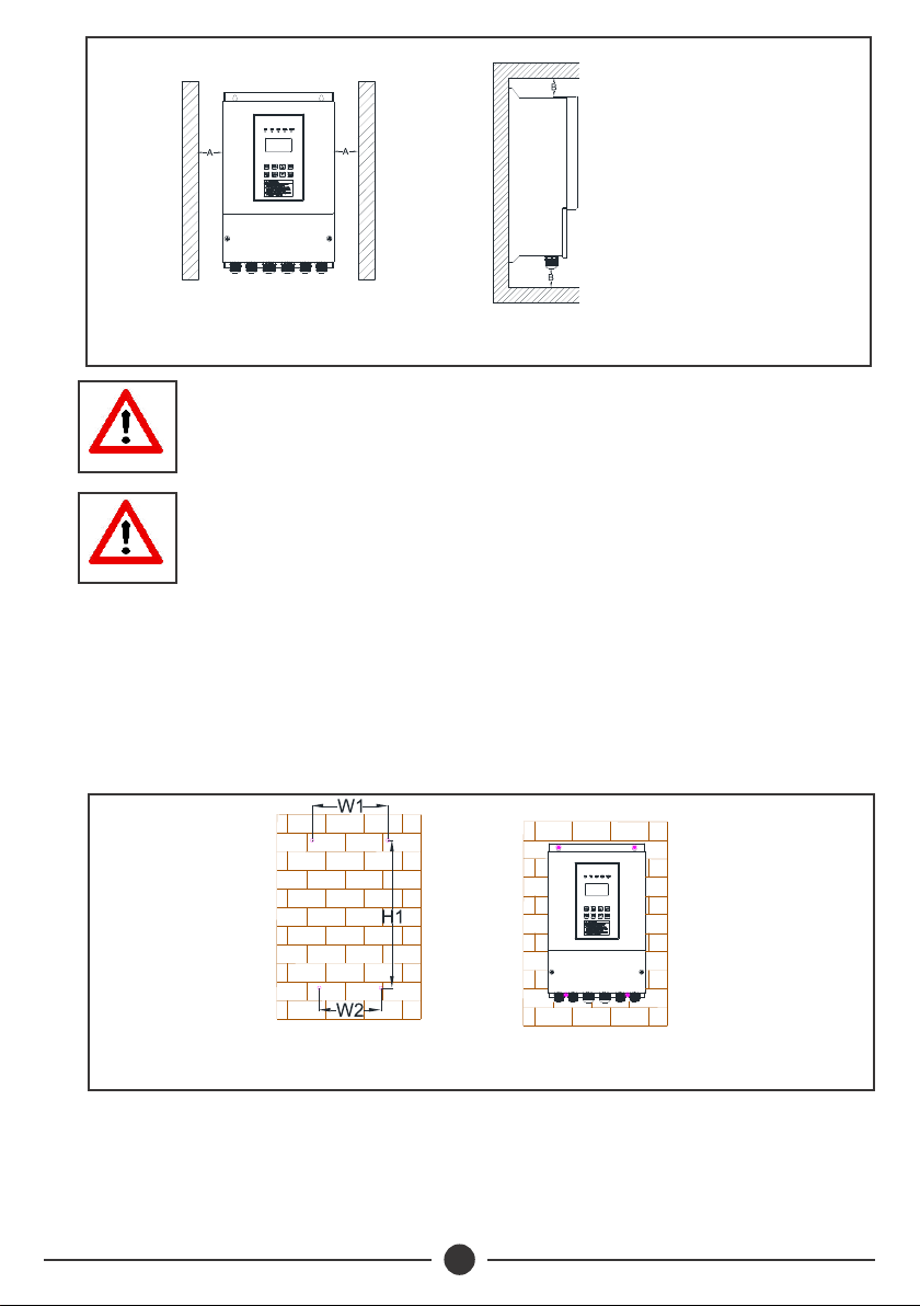
3.1 Installation Direction
ŸLeave enough installation space between inverter and other objects nearby to
ensure good ventilation and heat dissipation. As shown on Fig 1, please install the
0
invert vertically or backwards with maximum 10 inclination angle do NOT install it
horizontally or transversely.
ŸLeave enough space in front of the inverter, install the inverter at a height that is
convenient to operate device and read information in the LCD display screen
NOTE
Installation of the inverter according to the specied
environmental conditions is the precondition for ensuring
long-term normal and stable operation of the inverter.
6
Fig 1: Installation Direction Diagram
A >100mm
B>200mm
B>300mm for 11kW
NOTE
The installation surface should be at and closely attached to
the inverter bottom surface to ensure good heat dissipation.
NOTE
If multiple inverters are to be installed in the same cabinet, it
is recommended to adopt side by side installation. If two
inverters are to be installed longitudinally, a guide plate
should be added in the middle.
3.2 Installation Method
ŸChoose the installation place and drill holes according to the size and shape of
support plate, the recommended diameter of holes is 8±1mm with 60±5mm
depth.
ŸFasten the support plate on the wall with 35Nm tightening torque expansion
bolt.
Fig 2: Mounting Hole
Diagram
Fig 3: Inverter Mounting
Installation Diagram
ŸHang the mounting groove in inverter back on the support plate, when inverter
is reliably hung up, fasten the screw nuts between the support plate and
inverter.

47
Model
SV3/7.5T
SV3/11T
SV3/15T
SV3/18T
SV3/3.7M
SV3/5.5T
Dimensions (mm)
W2W1 H1
139
215 193
288
423
SV3/3.7T
SV3/1.5M
SV3/2.2M
SV3/22T
200 162 387
NOTE
Do NOT install the inverter on rocks or thin wooden panels
with toggle bolts.
NOTE
The expansion bolts provided by manufacturer are suitable
for installation on concrete walls. If the inverter is to be
mounted on wooden walls, select the expansion bolt suitable
for wooden wall mounting, and ensure the expansion bolts
are long enough to penetrate at least 1/2 of the wall
thickness.
PV
Disconnect
Solar Input
MCB
SV3
INVERTER
Tank Water Level Signal
Well Water Level Signal
Tank
AC Input
Water
Level
Switch
Water
Level
Switch
Well
3.3 Wiring Diagram
Fig 4: System Wiring Diagram
8
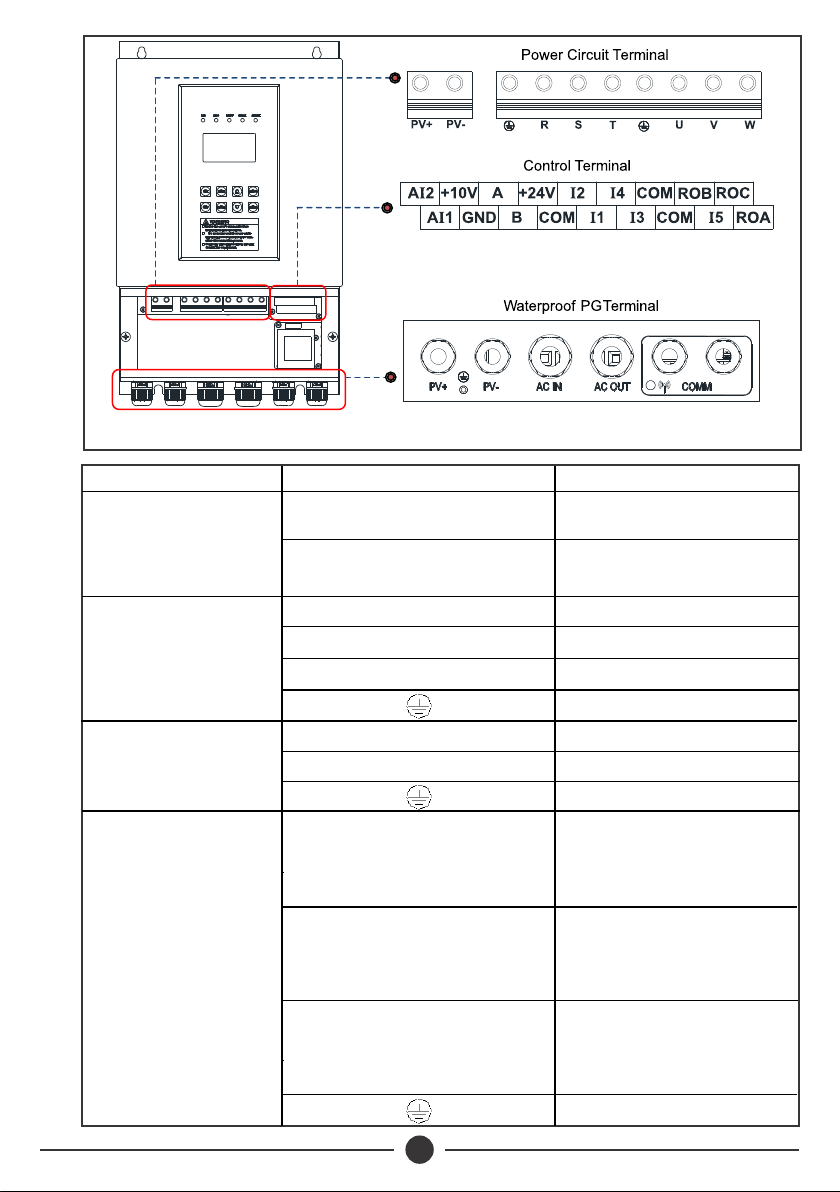
Fig 5: Wiring Terminal Diagram
4
DC Input
C o n n e c t e d t o p o s i t i v e
electrode of solar pv array
PV+
Socket Terminal Description Connection Description
PV-
Three - Phase
AC Input
R
Connected to earth cable
Connected to R phase of grid
U/A
Connected to U phase of
three-phase motor/auxillary
winding access terminal A of
single-phase motor
C o n n e c t e d t o n e g a t i v e
electrode of solar pv array
SConnected to S phase of grid
TConnected to T phase of grid
Single - Phase
AC Input
LConnected to L phase of grid
NConnected to N phase of grid
Connected to earth cable
AC Output Connected V phase of three
phase motor/main winding
access terminal M of single-
phase motor
V/M
W/C
Connected to W phase of
three -phase motor/main
winding access terminal C of
single-phase motor
Connected to earth cable

49
CAUTION
The input/output sockets are different for models, subject to
the silk screen on the inverter sockets and the terminal
description.
NOTE
For single-phase pumps, remove the external capacitor
before wiring
Switch input terminal 1
Tank water level signal input, open circuit is normal,
short circuit is abnormal. Function setting through
Pr15, default value 7
I1-COM
Terminal Terminal Name Function Description
Switch input terminal 2 Reserved. Function setting through Pr16, default
value 0.
I2-COM
Switch input terminal 3
Well water level signal input, open circuit is
abnormal, short circuit is normal. Function setting
through Pr17, default value 6.
I3-COM
Switch input terminal 4 Reserved. Function setting through Pr18, default
value 0
I4-COM
Switch input terminal 5 Woltman water meter signal input. Function setting
through Pr19, default value 3.
I5-COM
+24V power supply 24V power supply, maximum output current 300mA;
can be used as power supply of communication
module, external sensor or miniature relay
+24V-COM
+10V power supply
10V power supply, maximum output current 50mA;
can be used as power supply of an external
potentiometer with resistance value range of 1k
Ω~5kΩ
+10V-GND
RS485 communication
interface
Interface for communication with wired external host
or inbuilt wireless communication module. (Default
setting enable the communication with inbuilt
imodule, if needed for external host, relevant
advanced parameter must be modified)
A-B
Analog input terminal 1 Water level sensor signal input (default current type).
Range: DC 4~20mA
A11-GND
Analog input terminal 2 Pressure sensor signal input (default current type)
Range: DC 0~10V
A12-GND
Normal open relay contact Contact drive capability:
AC250V, 3A, cosØ = 0.4
DC30V, 1A
ROA - ROC
Normal close relay contact
ROB - ROC
410
NOTE
In order to ensure communication quality, use twisted
shielded pair cable as communication cable.
NOTE
All cables, analog, digital, power and signal should be
separated to avoid entanglement.
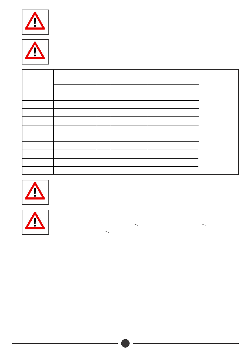
Model Solar Array
2
Cable (mm )
2
AC Cable (mm )
SV3/7.5T
SV3/11T
SV3/15T
SV3/18T
SV3/3.7M
SV3/5.5T
SV3/3.7T
SV3/1.5M
SV3/2.2M
SV3/22T
CAUTION
To ensure the system works normally, the cable size should be
selected according to the table above.
NOTE
(+)/(-) L/N R/S/T, U/V/W
2
Earth Cable (mm )
PE
Signal Cable
2
(mm )
4
6
10
10
4
4
2.5
2.5
4
10
6
2.5
4
4
6
10
10
6
4
2.5
2.5
4
10
1.5
2.5
4
6
6
2.5
2.5
2.5
1.5
1.5
10
The recommended cable should be used under the conditions
0
of ambient temperature < 40 C, cable length <100m and
working current < rated current.

411
3.4 Electrical Connection
Step 1 : Prepare all the input/output cables as shown in Fig 6.
Step 2: Open the cover of the inverter wiring area, pass the cable through the
waterproof PG terminal and fasten the corresponding cable connector with
a slotted screw driver. The tightening torque is 10Nm for the PV/AC terminal
and 7Nm for the signal terminal as shown in Fig 7.
Fig 6: Wire Process Diagram
Single Core Cable
Stripping Diagram
Multi Core Cable
Stripping Diagram
Single-Core Strip 10mm at A
DC Cable
Solar Array
Cable Type Process Description
Multi-Core Strip 50mm at A, Strip 10mm at B
AC Cable
Multi-Core Strip 50mm at A, Strip 5mm at B
Control
Signal
Cable
Fig 7: Wiring Diagram of Inverter Wiring Area

412
Step 3: Upon completion tighten the bottom waterproof PG terminal, close the wiring
area cover and lock it with a tightening torque between 10Nm and 12Nm.
Step 4: Fix the earth cable to the ground screw at the bottom of the shell as shown in
Fig 8.
Step 5: Wired Sunverter shown in Fig 9.
Fig 8: Grounded Connection Diagram
Fig 9: Wiring Complete Diagram
3.5 Single Phase Motor Wiring Instruction
ŸAs shown in Fig 10, remove the external capacitor on the single phase pump
and connect the inverter and single phase motor according to wiring
instruction.

413
Fig 10: Single phase Inverter Wiring Diagram
CAUTION
Ensure to connect the wires according to the instructions,
incorrect connection may lead to abnormal operation of the
system.
Wiring Reminder
In case single phase pump motor connection parts cannot be recognized, perform the
following steps to identify
Step 1: Test the resistance between each pair of the connection parts with a multi-
meter, the two ports with largest resistance value should be the main winding
M and auxiliary winding A, so the other one is common port C.
Step 2: Test the resistance between C and the other 2 ports, the resistance between C
and M should be relatively less and the resistance between C and A should
be much bigger.
Step 3: If the measured resistance in step 2 appears to have little difference, then
compare water flow during operation to determine if the wiring is correct.
Keep C port wiring unchanged, exchange the wiring of A and M and observe
the water flow. The wiring with bigger water flow should be the correct wiring.
From the above steps, the connection ports A, M,C of single phase motor can be
confirmed
3.6 Water Level Switch Installation and Wiring Instruction
The water level switch is installed in the well for dry running protection or installed
in the water tank for overflow protection.
Water level switch requires vertical installation with maximum 10° inclination
angle. The installation position should be slightly higher than the pump outlet
position in the well, while in the water tank it should be slightly lower than highest
water level as shown in Fig.11.

414
To wire for well application, pass the water level switch cable through the
waterproof PG terminal and connect to the I3 and COM terminals(remove the
short-circuit strip between the two first), for tank application, connect to the I1 and
COM terminals as shown in Fig. 12.
Fig 11: Water Level Switch
Installation for Well/Tank
Fig 12: Water Level Switch
Wiring Diagram
ŸA DC circuit breaker should be installed as protection switch for solar DC input.
ŸThe inverter has one pair of DC input terminals. If the solar modules are multi-
paralleled, an additional solar combiner box is necessary.
ŸThe inverter must be grounded reliably and the grounding cable properly sized and
as short a possible. If possible, the inverter should be grounded separately.
ŸIn areas with high incidence of lightning, it is recommended to install an external
surge protector at the power input of the inverter.
ŸIf the inverter is far from the motor (>200m), it is recommended to install on output
reactor or filter.
ŸIt is recommended to install input and output reactors, dedicated filters and
magnetic rings at the input and output of the inverter which can effectively reduce
the noise and avoid interference with other components.
ŸConsult nearest Davis & Shirtliff dealer for the extra accessories such as PV
disconnect switch/DC breaker, combiner, surge suppressor and reactors.
3.7 Others
4
Model
SV3/7.5T
SV3/11T
SV3/15T
SV3/18T
SV3/3.7M
SV3/5.5T
SV3/3.7T
SV3/1.5M
SV3/2.2M
SV3/22T
AC Breaker (A) DC Breaker
40
50
63
63
50
25
25
25
40
100
25A/1000VDC
40A/1000VDC
63A/1000VDC
63A/1000VDC
25A/750VDC
25A/1000VDC
16A/1000VDC
16A/750VDC
25A/750VDC
80A/1000VDC

415
3.8 Hybrid Installation
SV3 series solar pumping inverter provides PV and AC hybrid power input
function, as shown below, PV input is connected to bus circuit through anti-reverse
diode. Through anti-reverse diode and AC power input is rectified through rectifier
bridge then connected to bus circuit. Two kinds of power can be connected with
the inverter at the same time, and the hybrid power drives the water pump to work.
Hybrid Power Supply Main Circuit
Three Phase
AC Power Input
PV Array Input
Inverter
Bridge
PV+
R
U
PV-
SV
T
W
Fig 19
Hybrid Mode
Solar priority mode (Pr6=1) default.
Where there is both AC and PV power inputs, inverter adjusts pump running speed
prioritising solar power and only blends with AC power when there is insufficient
solar power. Insufficient solar power is detected when the pump speed falls to the
set value 30Hz.
AC+PV blending (Pr6=0)
When there is both AC and PV power inputs, inverter drives the pump running at
rated speed. Solar power usage is much higher when the solar irradiance is high
2
(near 1000 W/m )
Model SV3-M SV3-T
AC Input Voltage (VAC) 1PH/220V - 240V 3PH/380V - 415V
Recommended PV array voltage conguration:
As shown below, if the value of maximum power point voltage (Vmp) of the PV
array is equal to value of the bus voltage (Vdc) when the system is running, the PV
array will output the maximum power (Pmax). If Vmp deviates from Vdc, the more
the deviation, the less PV array power output. Therefore, in order for the PV array
to output the maximum power as much as possible, it is recommended to
configure the Vmp of the PV array to be near the bus voltage value Vdc. The Vdc
can be determined by the following formula: Vdc= √2 ∗V rms

416
NOTE
Vrms is the effective voltage value of AC power, such as 1PH
220V/3PH 380V
PV Array Curve
Voltage
Power
Pmax
Vmax V
Imax P
I
Model
Motor
Rated
Power
(kW)
Solar
Max
Input
Power
(kWp)
Output
Current
(A)
7.5
5.5
2.2
3.7
11
15
18.5
5.0
5.0
8
11
16
22
28
17
9
13
18
24
30
39
Max DC
Input
Voltage
Vmax
MPP
Voltage
VDC
450
850 600-700
1.1 2.2 8.6
1.5 3.3 11 150-360
Rated
Voltage
Output
1x220-240V
3x380-415V
324-370
22
SV3/7.5T
SV3/11T
SV3/15T
SV3/18T
SV3/3.7M
SV3/5.5T
SV3/3.7T
SV3/1.5M
SV3/2.2M
SV3/22T 32 45
Table of contents
Other DAYLIFF Inverter manuals


