Daystrom HEATHKIT HP-20 Installation instructions

Assem bly
and
Operation
of the
UTILITY
POWER
SUPPLY
MODEL HP-?O
-
HEA-- CCMPANY,
i d ^- : . .
lr^
I EIAY
IrJ STROM
IIEATIrKTT"
fl-ir-..-:
I DAYSTROM, : \coRpoRArEo
Lfl 12/7 /62
TABLE OF CONTENTS
Specifications. .
Introduction... .....
Theory of Operation. . . .
Construction Notes.
Parts List. .
Proper Soldering Techniques
Step-By-Step Proeedure.
Step-By-Step Assembly. . .
Testing The HP-20 power Supply.
Operation.
In Case Of Difficulty. . .
Service Information. . . .
Service.
Replacements.
Shipping Instructions. . . .
Warranty.
Schematic.
tFold-out from this page.
2
2
3
3
4
6
B
I
15
t7
77
1B
1B
19
19
20
7,N
A11 prices are subject to change without notice. The Heath
company reserves the right to discontinue instruments and
to_change specifications at any time without incuming any
obligation_to incorporate new ieafures in instrum""i"!""-
viously sold.
Copyrisht 1960
Heoth Compony

Page 2
SPECIFICATIONS
Power Requirements:. .
Overall Height:.
Total Continuous DC OutPut
Filament Power:.
Regulation (5070 load to 10070 load, from
hieh voltagetap):.....
Net Weight:. . .
Shipping Weight:.
11? volts AC, 50/60 cycles, 200 watts.
9" long, 4-3f 4" wide, 2-lf 4" high,
6" (with cover and four rubber feet).
1. 120 watts - 600 volts at 200 milliamperes
- or-
120 watts - 600 volts at 150 milliamperes
and 300 volts at 100 milliamPeres.
2. Bias - 130 volts at 30 milliamperes.
(Available in addition to above.)
6. 3 volts at 11 amperes, or
12. 6 volts at 5.5 amperes.
Approximately L0%.
12 lbs.
15 Ibs.
INTRODUCTION
The HEATHKIT Model HP-20 Utility Power
Supply was designed primarily to furnish all the
necessary power for HEATHKIT Mobile Trans-
mitters and Receivers, when they are used as
fixed station units.
Being a utility power supply allows it tobe used
to supply power to many other makes and types
of amateur equipment as well.
The Model HP-20 will supply a full 120 watts
of power, 600 volts at 200 milliamperes. A half
voltage tap (300 volts) is available for supply-
ing the receiver, or low leve1 stages of the
transmitter. In addition, 130 volts of negative
bias is available at a current rating (30 ma)
consistent with voltage regulator service. This
feafure allows use of the HP-20 Ydth SSB
equipment requiring regulated bias voltage.
The loads on the high and low voltage termi-
nals of the supply should be adjusted so that
the total power drain will not exceed 120
watts. A typical example would be a drain of
600 volts at 150 milliamperes from the high
voltage tap, which equals 90 watts. This would
leave 30 watts available at the low voltage tap,
or 300 volts at 100 miiliamperes. The total of
the two will equal the 120 watt rating of the
supply.
In event of a comptete short circuit in any of
the secondary circuits of the suppiy, two fuses
of the proper current rating afford adequate
proteetion.
The supply features excellent static regulation,
combined with the advantages of good dynamic
regulation, achieved through the use of high
value filter capacitors.
A full-wave voltage doubler circuit affordsgood
efficiency along with circuit economy. The
resultant ripple frequency is twice the source
frequency and, therefore, is easi.er to filter. A
further advantage is that each capacitor in the
doubler circuit requires a DC rating of only
half the output voltage, since the capacitors are
in series.
r^
DAYSTROM
rJ
IIEATI{ITIT'
i

|r^
I E,AYST
IrJ ROM
EEATEIKIT'
VAC
VAC RMS
voc
FREOUENCY
-l 30 E
FREOUENCY
OPERATION
the output voltage is concerned.
Page 3
600
6.3
12.6
THEORY OF
The conventional voltag+-doubler circuit used in
this power supply ha.s been chosen because of
its efficiency, economy and circuit simplicity.
A voltage-doubler circuit wiII deliver a DC
output voltage approximately twice the rms
value of the secondary winding of the trans_
former. Under very high current drains, the
output voltage may be slightly under twice the
secondary voltage.
In operation, the filter capacitors Cb and C6
are each chargedto thepeak voltage of the trans-
former secondary on alternate traf cycles, but
with polarities such that the DC voliages de_
veloped across the capacitors add, in so far as
Due to the low ripple content existing in the
waveform immediately after rectification (the
ripple frequency being doubled, as well as the
voltage), a minimum of filtering is required.
This is accomplished with a simple resistance
1$ capacity network, consisting of Rl, R2,
C7, and C8. A half-wave rectifier is used in
the bias supply. The blas supply filter network
c.onsists of C9, R6, and C10 with R? serving as
the bleeder resistor.
Ia order to provide good dynamic regulation,
high value output filter capacitors are used.
CONSTRUCTION NOTES
This manual is supplied to assist you in every
rl'a:,- ro complete your kit with the teast possibll
cha-nce for error. The arrangement shown is
rhe result of extensive experimentation and
tr:al. Ii followed carefully, the result will be a
stalle instr:ument, operating at a high degree
:: :::;:.:a'bi1it"'. we suggest that you retain the
*-;--:' i- -'-.,* fil
_-- --.- _. .. _ ..: rrres for future reference, both
rr- *_r-: _s; _: :he instrument andfor its main_
--l;; -.-i: :*: ::T C.Tfi.EFULLY AND CHECK
:.:-_i-: :-r:.: .. ^..:.-,il THE PARTS LIST. Lr so
: :..: .: :;:ai.nted with the parts.
Refer to the charts and other information on the
inslde covers of the manual to help you identify
the components. If some shortage or parts
damage is found in checking the parts List,
please read the REPLACEMENT section and
supply'the inJormation called for therein. Include
all inspection slips in your Ietter to us.
R-esistors generally have a tolerance rating of
10/6 unless otherrvise stated in the parts List.
Tolerances on capacitors are generally even
greater. Limits of +tO1Vo and -2070 are common
for electrolytic capacitors.
L JNE
F IL TER STEP-UP
TRANSFORMER VOLTAGE-DOUBLER
RECTIFIER RESISTANCE
CAPACITANCE
FILTER
HALF- WAVE
RECTIFIER RESISTANCE
CAPACITANCE
FILTER
117 VAC
RV5 6C-,
Il

t-
Page 4
We suggest that you do thefollowingbefore work
is started:
1. Lay out all parts so that they are readily
available.
2. Provide yourself with good quality tools.
Basic tool requirements consistof ascrew-
driver with a t/4" blade; a small screw-
driver with a 1/8" blade; Iong-nose ptiers;
wire cutters, preferably separate diagonal
cutters; a penlmife or a tool for stripping
insulation from wires; a soldering iron (or
gun) and rosin core solder. A set of nut
drivers and a nut starter, while not neces-
sary, will aid extensively in construction
of the kit.
Most kit hrilders find it helpful to separate the
various parts into convenient categories. Muffin
tins or molded egg cartons make convenient
trays for small parts. Resistors and capac-
itors may be placed with their iead ends in-
serted in the edge of a piece of corrugated
PARTS
cardboard until they are needed. Values
be written on the cardboard next to each
component.
IMPORTANT NOTE: The #57-20 silicon diodes
supplied in this kit will meet all circuit re-
quirements, but may appear different than shown
in the parts pictorial and other sections of the
manual. The accompanying illustration shows
some of the silicon diode types that may be
supplied.
ANODE ENDS
, NE6ATLVE (-)
CATHODE ENI
POSiTIVE +)
PART
No. PARTS
Per Kit DESCRIPTION
220Alwattresistor
(red-red-brown)
100 KC} 1 watt resistor
(brown-black-ye11ow)
100O7wattwire-wound
1070 resistor
30 KO 25 watt wire-wound
center tapped resistor
.001 prfd GMV 1400 V disc
ceramic capacitor
125 p,fd 450 V twist prong
electrolytic capacitor
40 pfd 450 V electrolytic
hrbular capacitor
20+20 ptfd 150 volt capacitor
1-lug terminal strip
Z-Lug terminal strip
4-lug terminal strip
5-Iug terminal strip
3-lug terminal strip
3-1ug terminal strip, #B foot
Octal socket
L IST
PART
No.
346- 1
346-10
347-18 1
Metal Parts
200-M279F396
204-M198
205-M168F
Hardware
250-B 8
250-18
2 50- 56
250-89
250- 12 3
252-3
252-4
252-30
PARTS DESCRIPTION
Per Kit
Resistors-Capacitors
1A-19
1A-28
3G-9
3Y-3
2L-71
25-34
25-36
25-80
1
1
2
1
4
2
2
1
Plus-socket-Terminal Strips (Cont' d.)
438-11 1 Plug, AC fused
438-22 1 Octal plug
Wire-Cord-Sleevinq
ffiinecord
344-1 4 Length hookuP wire
Choke - Switch- T ransf ormer
45-L7 2 Line choke
54-109 1 Power transformer
61-1 1 SPST toggle switch
Plug- Socket- Ae t rI!44 J!!4_q
1
2
1
1
1
7
6
4
1
(1 each-black, orange,
yellow, red)
Length insulated sleeving
Length 3/8" fiber glass
sleeving
Length 8-conductor cable
C-:assis
[lounting bracket
Bottom plate
#6 x 3/8" BH sheet metal
screw
8-32 x 3,/8" RHMS
6-32 x 1/4" BHMS
6-32 x 3/8" BHMS
10-24 x 2-l/4" slotted hex
head screw
6-32 x 1,/4" nut
8-32x3 B"nut
10-2i :ex nut
431-1
431-2
431- 5
431-1 1
43t-27
431-33
434-39
1
1
3
2
1
1
1
10
11
1
I
IIEATIII(rT'
-
-
I

,I
Ir^
I EIAY
ltJ STROM
ETAIIIIilT'
2)3-7 I
.,1=4,_/., ?
254-1 10
254-2 11
255-41 4
90- 10 1
261-6
391- 7
472-10
421-2
440-l
481-3
Miscellaneous
=10 fiber shoulder washer
t/2" x 3/16" flat rvasher
=6 I:.cr'.','asher
:6 iC,:..'.','a She r
Sj.licor recr,ifier (500 ma)
3/8" rui:oei {ronlmet
i / 16" rui,.'rel grommet
.:-R,T PARTS DESCRIPTION
I'r Per Kit
H=r'dware (Cont'd. )
PART PARTS DESCRIPTION
N!. Per Kit
Miscellaneous (Cont' d. )
Page 5
Cabinet cover
Rubber feet
Nameplate
Neon pilot light
3 amp fuse
Octal plug cap
Capacitor mounting wafer
(fiber)
Solder
Manual
1/4'' SPACER
#255-41
3/16" x 5/16"
RUBBER GFOMMET
s 13-4
1
4
1
1
2
1
2
57-20
?3- 1
73-4 1
5
1
1336- 1
595-363
o
6-32 NUT 8-32 NUT
#252 4
r - :, .i ::::: j10-24 NUT
#252-30
DUAL 20 pFD 150V
ELECTROLYTIC CAPACITOR
#25_80
OCTAL SOCKET
!434-39
r
F=+250-E!
fhss!
" 8-32 x 3 /8" RH-\IS
#250-18
$$sssn$ss$$sfifi$$ r
10-21 x 2 1/4"
SLOTTI]D HEX
HEAD SCREW
*250-723
@@
#10 FIBER
-
1 "2 s : -: .: :ri;:l ffi
iFs* #6 x 3/B, BH
SHEET MET,{I SCRE\I'
#250 B
lOOO?WATTRESISTOR
#3G-9
OCTAL PLUG CAP
4440-7
--t-r-_ ;-'- a
--: =l=01:nl
. '!. t.-i.l,ti
3/8" x9/32,'
RUBBER GROMMET
001 lLfd
DISC 1400 voLT
CERAMIC
CAPACITOR
40 -::-: -
... H
\*r-f-''--. i,-, -l.:::-alaIEF
--r:-:
12r -id{50 VOLT
Eii.TFO LYTIC CAPACITOR
-25 34
@
:1.,:=:-' a,: - -
ffi
] :::;:I]
G L-r. S: : - : a 1,-I\ G
'311-:0 1-LUC
TERMINAL STRIP 3-LUG
TERMINAL STRIP
#431-27
d!H!}
L,
r ILG
:J]:];.\I STRIP
'-M 11
4-LLG
?ERM1NAL STPIP
*431 t3_LUG
TERMINAL STRIP
#B Foot #431-33
2 LUG
TERMiNAI STRIP
4131-2
o
l,-rT i-:---, l,:il.
(-, =)
L^l
U

ROM
trA
I oAYST
ltJ
ITEATIIKTT'
PROPER SOLDERING
OnIv a small percentage of HEATHKIT e$rip- 3'
;;tit;;ffi;s'ers find it necessarv to return an
i;;i;"il;;a for factorv service' of-these instru-
'#i"ltE,' uv ; ^i- tr, " r i" ri e s t p o r t i on-o-t m alf uncti on s
are due io poor or improper soldermg'
If terminals are brightandcleanandfree of wax'
f";;;a insulation *a ott'u' foreign substances'
""'oiiii""itv will be experienced in soldering'
Correctly solderecl connections are essential if 4'
the performance engineered ilto .a kit is to be
irirv--*"tiir"a. If you are .a .le,sinner with no
"ruLri"""" in solaering, a haU hour's practice
*iif, "o*" odd lengths of wire may be a worth-
while investment.
For most wiring, a 30 to 100 watt iron or its
"q,ri"-"i&t in a so*idering gun is very satisfactory'
A'1o**" wattage iron than this may not heat the
"t""u"tio" eno'ugh to flow the solder smoothly
or.* tfr" joint. Keep the iron tip clean and bright
tr- *ipi"! it from time to time with a cloth' 5'
Page 6
CIIASSIS WIRING AND SOLDERIhG
1
2.
TECHNIQUES
Leads on resistors, capacitors- a,nd similar
components are gene"afly much longerthan
il;y ;;;A to be "to mat<e the required con-
,r""lio"t. In these cases, theleadsshouldbe
ffi;;fier length before thepartis added
io -ttt" "fr""sis. t: general' the.leads -:,l?y]d
te lust long enough to reach their termrn-
ating points.
Wherever ttrere is apossibility r:f 'bar* teads
;h;"ti"g to other p*its o: ':r:rthe*ha*sis'the
i;;;t lhould be eove;eil x'rt!:: irrsulating
"i""ti"s. where the use oi sieeviug- is spe-
Iiircriiv'i"tended, the phrase "use sleeviRg"
i" it"i,ia"a in the asiociated construetion
step. Il:I any case where there is the pos-
tiuiirtv oi "r" unintentional short circuit'
;i;;;ils strouto be used. Extra sleeving is
provided for this Purpose'
Crimp or bend the lead (or leads) aroundthe
t-e*minri to form a good ioint without re-
iil;-;; solder for phvsical strength' If
iiJ'"*ir- it too iarge to allow lrending or if
;il; ;i;p siates trrat ttre wire is not to be
;;i*p-e, position the wire so that a good
t"iau" connection can still be made"
Unless otherwise indicated, all. wire used
;'th" type with colored insulation (hookup
;J, ttre size of the conductor is thesame
i;; ;n ;;;; of hookuP wires furnished with
it i" Lit. Inpreparing a Iength of hookup wire'
I /i" of insutation should be remcved from
"'""r, "rri ""Iess directed otherwise in the
construction steP.
To avoid breaking internal connect'ions when
"iripptns insulati-on frorn the leads of trans-
;;;;;#"r similar components,. ga1e should
;;iai<;; not to pu1l directlv on the igld' h-
"i""d,-iirfO the lead with pliers while it is
being striPPed.
6. Position the work, if possible, 3o that gravity
*iir r,.rp to keep ihe-solder where yor: want
it.
Place a flat side of the solciering iron tip
**ri".i *,. joint to be soldered until it is
;:;;- suttrcienttY to melt the solder'
Then place the solder against the heated
i""*i"tf and it rrill immediately flow over
7
iI
B"

ll\
I oAYSTR
IrJ OM
EEATHITIT'
IRemove the sold:r -i ihen the iron from
the completed j'.rr.c::-:. Use care notto move
the leads unril ::r s - iler is solidiJied,
CRIMP WIRES HEAT CO\}'ECTIO\ APPLY SOLDER
the joint; use only enough solder to thor-
oughly wet the junction. It is usually not
necessarj/ to f i11 the entire hole in the
terminal. cith solder.
COLD SOLDER JOINT
CO\f E C TIO\ INSUFFICIENT LY
HE.{TED
Page 7
A poor or cold solder joint wiII usually Iook
crystalline and have a grainy texfure, or the
solder will stand up in a blob and will not have
adhered to the joint. Such joints should be re-
heated until the soider flows smoothly over the
entire junction. In some cases, it maybeneces-
sary to add a little more solder to achieve a
smooth bright appearance.
ALLOW SOLDER
TO FLOW
PROPER SOLDER
CONNECTION COLD SOLDER JOINT
CONNECTION MOVED
WHILE COOLING
RosL\ Llar:.: :o--r:P. HAS BEEN SUPPLIED WITH THIS KIT. THIS TypE oF soLDER
\ltsf :: -,-::; FoF. .{LL SOLDERNG IN THIS KIT. ALL GUARANTEES ARE voIDED
A\D 'N'' ',i:- - \OT REP.{IR OR SER\IICE EQUIPMENT IN WHICH ACID CORE SOLDER
OR P.{S.: TI LXES HAVE BEEN USED. IF ADDITIONAL SOLDER IS NEEDED, BE SURE
TO PL?.CL:--ir RO'SINCORE (60:40 or 50:50 TIN-LEADCONTENT)RADIOTYPE SOLDER.
ri
\I

Page 8
STEP-BY.STEP PROCEDURE
The following instructions are presented in a
logieal step-by-step sequence to enable you to
complete your kit with the least possible con-
fusion. Be sure to read each step all the way
through before beginning the specified operation.
Also read several steps ahead of the actualstep
being performed. This will familiarize you with
the relationship of the subsequent operations.
When the step is completed, check it off in the
space provided. This is particularly important
as it may prevent errors or omissions, espe-
cially if your work is interrupted. Some kit
builders have also found it helpful to mark each
lead in colored pencil on the Pictorial as it is
added.
The fold-out diagrams in this manual may be
removed and attached to the waII above your
working area; but, because they are an integral
part of the instructions, they should be returned
to the manual a.fter the kit is completed.
In general, the itlustrations in this manual
correspond to the actual configuration of the
kit; however, in some instances the illustra-
tions may be slightly distorted to facilitate
clearly showing all of the Parts.
The abbreviation 'tNS, indicates that a con-
nection should not be soldered yet as other
wires will be added. When the iast wire is
installed, the terminal should be soldered and
the abbreviation "S" isusedto indicate this. Note
that a number will appear after each solder
instruction. This number indicates the number of
leads that are supposed to be connected to the
terminal in point before it is soldered. For
example, if the instruction reads, "Connect a
lead to lug 1 (S-2)," it will be understood that
there wilt be two leads connectedtotheterminal
at the time it is soldered. (In cases where a lead
passes through a terminal or lug and then con-
nects to another point, it will cotmt as two leads,
one entering and. one leaving the terminal.)
The steps directing the installation of resistors
include color codes to help identify the parts.
Also, il a part is identified by a letter-number
designation on the Schematic, its designation
wiil appear inthe construction step which directs
its installation.
EEAASET

lt7 v.
50-50 \
LI
3 AMP FUSE LINE CHOKE BLACK
PI LOT
LICHT
.oot .ool UFD
.oot UFD .00t urD
3 AMP FUSE LINE CHOKE L|NE SwtTCH BLACK
L2 S1
BROWN
BROWN
RED
'i--:,t-3-rE
EEN
t2.6V.-4 A.
JUMPER
6 3V-
JUve6P
lA
I o:,-EA I
ll r/PFg
25a =t,,S 5 A-
a3"-4A
E
E
I
lI
cro
E
E
?o
@UFD
?o
,TIFD
D3 D4
C7 + 125 LlFD
+ 40 UFD
loo J1 7w
roo_n- 7 w
+600v
+300v
EE
100KJt
1w
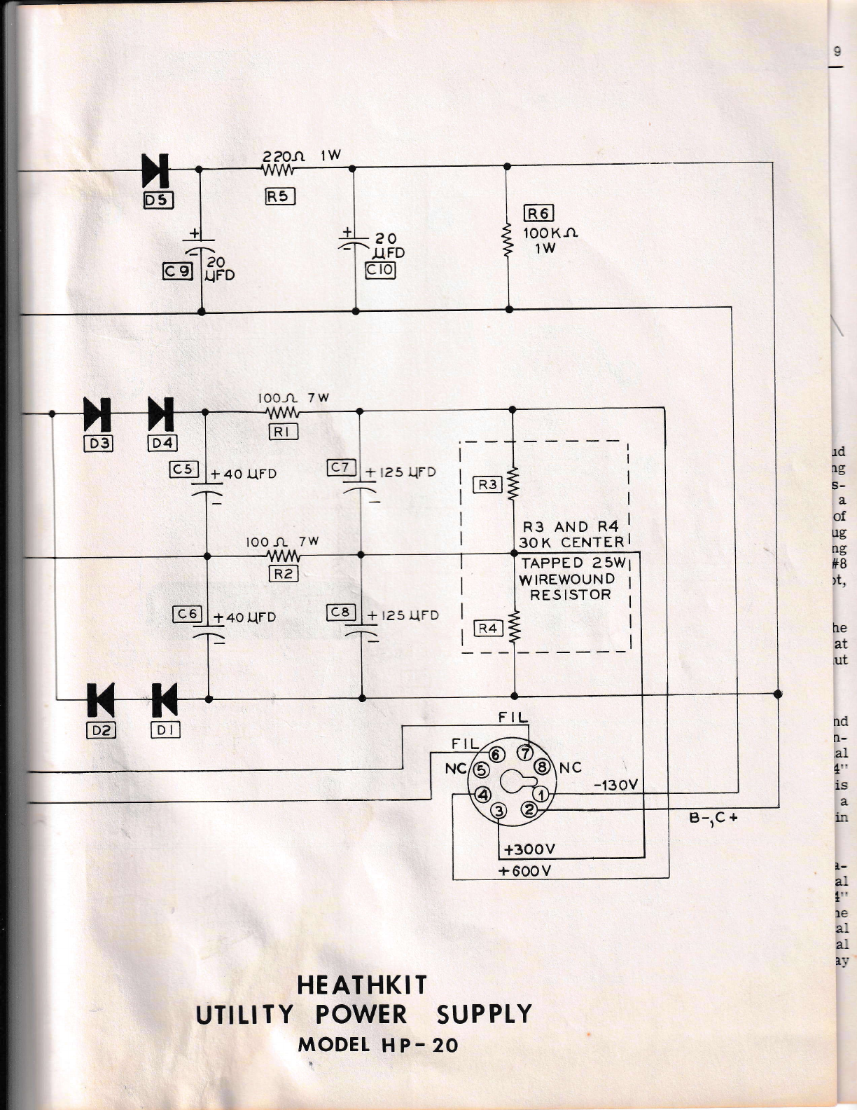
R3 AND R4
30K CENTER
TAPPED 25W
W IREWOUN D
RES ISTOR
c6
R2
DI
+ l2s UFD
+40 UFD
NC -'130v
F
E
z?On lw
HEATHKTT
UTILITY POWER SUPPTY
MODET HP.20
he
at
ut
ud
NG
s-
a
of
ug
ng
#B
)t,
nd
n-
dL
4"
is
,
ix
I.
dL
1"
1e
ar
tr:,'
B-rc +
E
EE
-T.
@@

@
@
ffi
o
@
@
A,)
w
KEYWAY
Pictorial 1
L

BLACK
Figure 2
,!
-4
BLUE
YELLOW
BLUE-YELLOW
YELLOW-GREEN
BROWN
@
6
t8-3? NUT (4)
+e locxwasHen (a)
{sro.rn 1o;
e
e
L
: - i'
o
,s
a.
MOUNTING
FOOT
sJ) \\
0
@
o
I
Figure 3

lr\
I DAYST
ltJ FIOMEEATHITIT' Page 9
Ref er to Figure 1 f or the f ollowing step.
( ) Insert the r'*'o sruds of the namepiate in
the two hoies in the chassis f ace side,
orierrting as shosr. \\hile holdingthe name-
plate tight to the :l-.assis, melt the studs
do*n with a hot s:-i:::::E i.ron r.rntil a smali
fiat retaininq 'ceai :s :::=ed.
STEP.BY.STEP ASSEMBLY
o
Refe
(r4 r to Pictorial 1 :,:r :he i--li:*ing steps.
Mount a 4-Iug re:'r::-a- sr:i: a: -_caricn CC.
Orient the termi::ai sir:: as s::atl. Use a
6-32 x 1/4" Brnder Hra;. ]Ia::i:re Screw
(BHMS) through the c:assis. r:rE n:.c.-:rting
foot of the terminal. sir::. a =6 l:lk-r,asher
and secure with a 6-32 n;i.
e
NOTE: The plastic nut holder sill be found
convenient in the mounting of these con:ptnenrs.
(:i ) Mount a 4-Iug terminal strip at locatic::.DD
and a 2-1ug terminal strip at locatr:n EE
(on the same screw). Face the ter::inal
strips as shorm in Pictorial 1 anri F:.i.r.:.re
6. Use a 6-32 x L/4,, BHMrS thrc'qh -Jre
chassis, the two mounting feet. a 16 -;ck-
washer, and secure with a 6-32 nut.
{1Mount a third 4-1ug terminal strip ar -:-
cation LL, as shown. Use a 6-32 x I .i"
BHMS, #6 lockwasher and 6-32 nut.
\/) Locate the powertransformer (r54-109) a:r:
refer to Figure 2. Measuring straight out
from the transformer bottom shell. cut the
two red leads and one of the brosrr leads
to A-Lf 4". Trim approximately b,, 16" of the
insulation off the ends.
NOTE: In the following steps, when instructions
are given to strip the ends, strip b/16" of in-
sulat/bn in each case.
( fI Cut one black lead to 3" in length and the
other to 2-L/2" i:r length. Strip the ends,
Save the two pieces of excess wire as they
will be used later.
Figure 1
( ,) T1. Slip a L/4,, spacer onto each 8-'32 stud
and seat the transformer into its mounting
position. See Figure 3. Secure the trans-
former on the chassis bottom side with a
#8 lockwasher and an B-32 nut on each of
the three sfuds, as shown. Mount a 3-tug
terminal strip at QQ (has an 8-32 mounting
foot) on the transformer stud, Use a #B
lockwasher first, then the mounting foot,
and the 8-32 nut last.
( ) 51. Refer to Pictorial 1 and mount the
single-pole single-throw (SPST) switch at
location A, with the lockwasher and one nut
on ttte inside of the chassis.
( ) Scrape or sandpaper any paint from around
the holes at locations GG and IIH on the in-
side of the ehassis. Mount a b-tug terminal
strip at location GG, using a B-52 xL/4,,
BHMS, #6 lockwasher between the chassis
and the mounting foot, and secure with a
6-32 nut. Orient the strips as shown in
Pictorial 1.
( ' .'I'Mount a seeond 5-Iugterminal strip at loba-
tion HH. At the same time, mount the octal
power socket at location P'using 6-82xL/4,,
BHMS, #6 lockwashers and 6-82 nuts, The
#6 lockwasher is used between the octal
socket and the mounting foot of terminal
strip HH. Orient the socket with the keyway
as shown in Pictorial 1.
Cut each of the remaining five colored
leads (blue, brown, yellow, blue-ye11ow,
and ye1Iow-green) to Z-g/4,, in lgngth.
Strip the ends. Save these piecesof wirefor
use later.
({
Page 10
a-szrf'nr.rus (s)
q..
G.
lr3
2"t6 FLAT WASHER (3)
,8 LOCKWASHER (3)
NUr (3)
#6 LOCKWASHER (4)
NUr (4)
igure 4
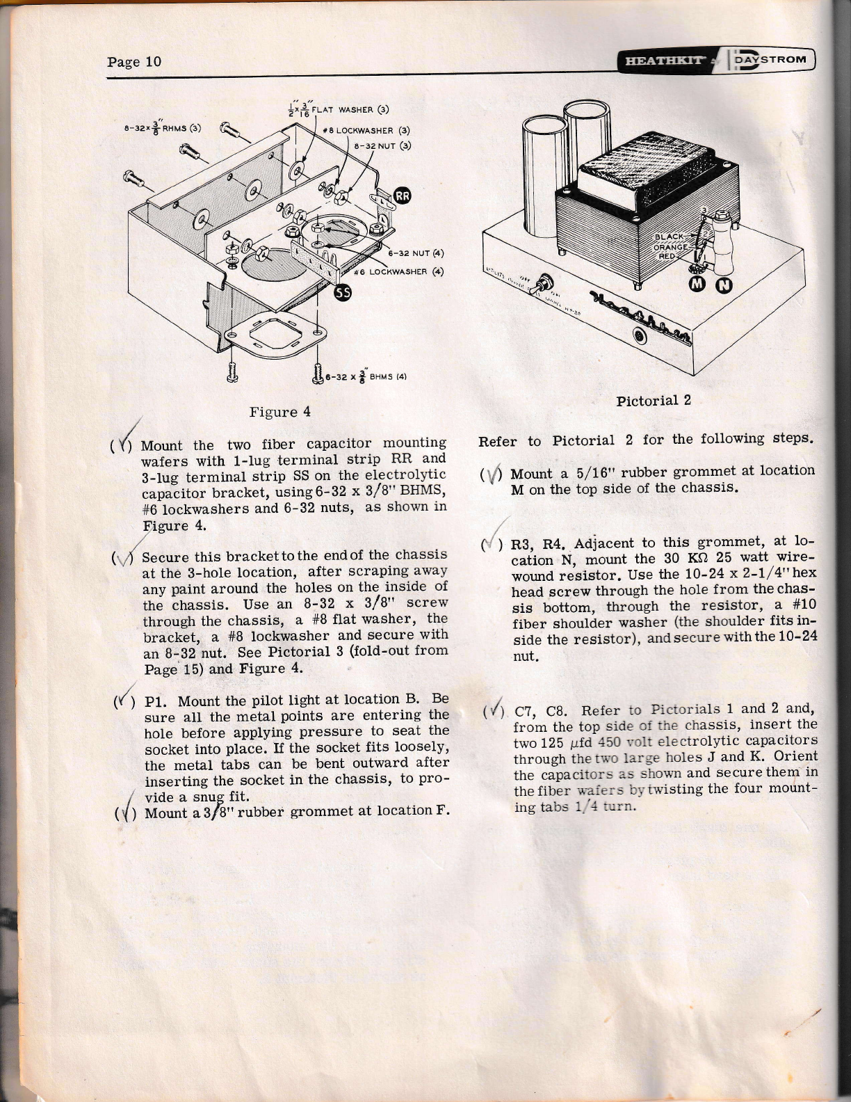
( () Mount tire two fiber capacitor mounting
wafers with 1-Iug terminal strip RR and
3-Iug terminal strip SS on the electrolytic
capa;itor bracket, using6-32 x 3/8" BHMS,
#6 lockwashers and 6-32 nuts, as shown in
Figure 4.
(.-4 Secure this brackettothe endof the chassis
at the 3-hole location, after scraping away
any paint around the holes on the inside of
the chassis. Use an B-32 x 3/8" screw
through the chassis, a #B flat washer, the
bracket, a #B lockwasher and secure with
an B-32 nut. See Pictorial 3 (fold-out from
Page'15) and Figure 4.
-.. r $'u.,u. ,ot
({) Pl. Mount the pilot light at location B. Be
sure aII the metal points are entering the
hole before applying pressure to seat the
socket into place. If the socket fits loosely,
the metal tabs can be bent outward after
inserting the socket in the chassis, to pro-
, vide a snug fit.
( { ) n{ount asf9" rubber grommet at location F.
Pictorial 2
Refer to Pictorial 2 for the following steps.
( ; ) Mount a 5f L6" rubber grommet at location
' M on the toP side of the chassis.
rl
(
R3, R4. Adiacent to this grommet, at 1o-
cation N, mount the 30 KO 25 watt wire-
wound resistor. Use the tO-24 xZ-lf 4"trex
head screw through the hole from the chas-
sis bottom, through the resistor, a #LO
fiber shoulder washer (the shoulder fits in-
side the resistor), and secure with the 10-24
nut.
'/1 Cl, Ca. Refer to Pictorials 1 and 2 and,
from the top side :f rhe chassis, insert the
two 125 p.fd -150 ''';1t electrolytic capacitors
through the t'i,'o large holes J and K. Orient
the capacitor> 3s shoun and securethem in
the fiber -*-aie:'5 r--'1,-trvisting the four rnount-
ing tal-.s 1.'l t;rn.
tr-
I DAYST
lt- ROM
EEATEET
I

lr=
I DAYST
ltJ ROM
Er!{TfIIilT" Page 11
i
tl
f
{l
f
];OTE: Refer to pictorial 3 (fold_out from page
1 5) for the following sreps unless otherrvise noted.
( r ) Conneet the longer black lead from the
transforn:er tl lug 2 of rhe SpST s*itch at
location A (\-S).
( .') Connect one pitcr l:;ht Iead to the sar:e lug
.2 of the SpST sr:r::. S_2 .
(/) Strip both er-:s :j -.:-: -::.:::;i:ce :: c-ack
wire u.hich a.as ,.,.=----a= _,t :h: Iralts_
former. Ccn::e:: _:. =:l:- -.. 1 :::n= SpST
switch (S-1). R:_:e -_:.= _-r... :nj C_rn
along ttre chass:s a:.1 . ::-:--::: :: :: -*: i ,:,f
terminal strip HH ,-:-S .
( ) C+. Cut both lead-c :: ..--- _:: _i_, -,,.,1t
disc ceramic capaciicl r_ j a .- ';-;th
Connect one end to 1ug i ,: :=.=^-.. .;rip
HH (NS). Connect thJct;: =-.: :: -..:* 3
of terminal strip HH (NS).
(') L2. Cut both leads of a line ct:.:. t-- t 2,,
in length. While retaining the er: :*:rs of
the coil by holding them *ttir :arr_,;._:ose
pliers, bend both ieads axia_ll,,. t: f a::.:rare
mounting, as shown in pictoi:.- 3. SLi:: a
piece of the latge 3/9,' sleer.irs :-,,=r -,*,re
choke coil. Cormect one end t: -.:: i of
terminal strip GG (NS). Comecr r.e- _:hEr
:nd to lug 4 of terminal strip HH S_ 3).
Trim off excess lead length.
( ) Connect the remaining black leac frci:: rhe
transformer to lug 2 of terminal. s::-:r HH
(NS).
(.. ) Route the remaining pilot Iight ieaC,.::rder
the line choke, as shown, andlonnecr tothe
same tug 2 of terminal strip HH (NS).
(") C:. C-:r rhe leads on another .001 =id 1400
volt d"isc ceramic capacitor to 3 g,,in
Iengt. C,tl:-iCr one end to lug 2 of terminal
strip IiH \ S . C onnect the other end to Iug B
of ter=r.a- s:i-:: HH (S_2).
( ) Lt. Cut both leads on another line choke to
l/2,, in 1ength, form the leads axially as
before, and slip_a piece of B/8,, steeving
over the choke. Connect one end to lug 2 oi
terminat strip GG (NS). Connect the oth""
end to lug 2 of terminar strip HH (S_4).
(' ) Cut a piece of the remaining blue-yellow
wire to 2,, in length and strip the ends.
Connect one end to lug 1 of terminal strip
LL (NS). Conneet the other end to lug ? ot
the power output socket (S_1). Use cale in
soldering to avoid shorting this lead to the
socket frame.
( {Connect the blue-yellow lead from the trans-
former to lug 1 of terminat strip LL (NS).
( t ) Connect the blue lead from the transformer
-!o lrg 2 of terminal strip LL (NS).
( "/) Connect_ the green-yellow lead to lug 3 of
terminal strip LL (NS).
(i ) Conneet the ye1low lead to 1ug 4 of termi_
nal strip LL (NS).
) Cut a piece of the leftover yellow trans-
former lead to B-l/2,, in tengtfr. Strip the
ends.Tin one end Iightly with solder and route
this lead down under the other filament
leads and connect to lug 4 of terminal
strip LL (NS). Connect thi remaining lead
to lug 6 on the power output socketis_f l.
NOTE: Now decide whether this supply is to
deliver 6.3 volts AC at 11 amperes or LZ.6
volts AC at b.5 amperes forthefitamentcireuii.
ff, the supply is to be used with the HEATHKIT
Mode1s MR-l and MT_1, select the filament
voltage for which the transmitter and receiver
have been wired.
SELECT AND PERFORM THE STEPS FOR ONLY
ONE, NOT BOTH, VALUES OF FILAMENT
VOLTAGE.
fr:
,x
il

I
Page 12
Detail 3A
FOR 6.3 VOLTS AT B AMPERES (See Detail 3A )
( .) Cut pieces of the leftove and green-
leads to 2- length. Strip the
ends tin lightl Connect ttre green-
yellow Iafrom iug 1 (S-3)
to lug 3 (S-2) rminal strip LL.
( ) Connect .ue a jumper from 1ug
2 (s-2) lug 4 (s-3) strip LL,
This cthe wiring for 6.3 ilament
FOR 12.6 VOLTS AT 4 AMPERES (See Pictor-
ial 3):
(t4 Cut one piece of the remaining blue lead to
Z-l/2" in length. Strip the ends and tin
lightly. Connect this lead from Iug 2 (S-2)
to lug 3 (S-2) on terminal striP LL.
(."') Solder lue 1 (S-2) andlug.! (S-2)of terminal
strip LL.
(ly) Cut a piece of black hookup rj.re 6" in
length. Strip the ends. Connect one end to
lug 2 of the power output socket (S-2).
Connect the other end to lug 1 on the 125
prfd capacitor at location K (NS). Route wire
. as shown.
/
This completes the wiring for 12.6 voltfilament
operation.
( \) Strip a short length of hookup wire and con-
nect this bare wire fiom lug 2 of the power
output socket (NS) to the adjacent socket
ground lug (S-1).
) Cut a piece of orange wire to 2't/2" in
length. Strip the ends. Connect one end to
Iug 3 on the power output socket (S-1).
Connect the other end to lug 4 of the 125
pfd capacitor at location J (NS).
( ,) R2. Cut one lead of a 100 Q 7 watt resistor
(#3G-9) to 5f 8" in length. Cover the other
lead with a piece of insulated sleeving 1-
lf 4" in length. Connect the short leadtolug
1 of terminal strip HH (NS). If the resistor
supplied is the square body type, face the
"filled" side of the resistorupward, or away
from the power output socket, otherwise rest
the resistor body against the socket. Con-
nect the insulated lead to tug 4 of the 125
trrfd capacitor at location J (S-2).
) Cut a piece of black hookup wire 9" in
length. Strip the ends, Connect one end to
lug 5 of terminal strip GG (NS). Connectthe
other end to lug 1 of the 125 pfd capacitor
at location K (NS). Route wire as shown.
( ,) Cut another piece of black wire 6-1/2" in
length. Strip the ends. Connect one end to
1ug 5 of terminal strip GG (NS), routing
close to the chassis. Connect the ottrer end
to lug 1 of terminal striP DD (NS).
) Cut another piece of black wire 6-1/2" in
length. Strip the ends. Connect one end to
Iug 3 of the 30 KA 25 watt bleeder resistor
(S-1). Route the other end throughgrommet
M close to the chassis and connect to Iug 1
of terminal strip DD (NS).
) Cut a piece of orange wire L-L/Z" in
length. Strip the ends. Connect one end to
1ug 3 of the 125 pfd filter capacitorJ (S-1).
Connect the other end to lug 5 of the 125
prfd fitter capacitor K (S-1).
STROM
-
DAY
J
rIE:aI'rrrtr"
-
t

lr-
I E,AYST
ItJ ROM
f,EATIIKIT'
Cut a piece of ,trarrie l,L-,,-rtup u-it'e 10" in
length. Strip tle e:is. Fl'o:r the botton-) slde
of the chass;s, -:s.r': -r: ir-d ull th1'ough the
5/16" rui,r-'ter =:- r:1::-:: -'',- :.ilacent to the 30
Kf,) bleeciei :'.srs:-:'. ---:'.i:Jnn.c: to Iug 2
of the bleecer- t'.:-i:-: S- i Route the other
Iead end clos€ :-, ::.: , :: i-:. ncitl tell:tinal
strips GG and ii:.. ..:. j _:::-ecl ii 1ui 1 of
the 125 -icl::-:... ..: . : ;: -. rr-,ir J
+
CATHODE
Page 13
ANODE
/c- r
\v rr,
(') Cut a -r::=:= -: -:' LEA
s
in lenfl:. S:: -: :.-.. .:'. r:, ? - i:a ::;i efld
down r.mde: ::-: -:..= .. --::-i. . --s: t- Ihe
chassis, an.l --:j-:-, : --: : -: t;r:::inal
strip QQ (r.-S; --:-< 1 -:-.: I .:'= :,i used).
Comect the :.,:.=: :..t :- -'.- - -::::ntinal
strip HH (S-2 .
Cut a piece c: t:: .-. -i:--* ';::': :-1 2" in
length. Strip tre =..:=, I -.-..=:: ---= =nd to
Iug 4 of the r-;:r -:- -: -i ..:-: S-1).
Connect the other c:"1 :: ,lu
filter capacitor J );S ,
(o4 Cut another piece :: ::-- ..:-.:-'- ',i::. 11"
' in length. Strip L:.= :..-:. I. .:. -:.: :od
down close to the ci:ass:s. --. t::' :.-.a -_:',i'er
output socket, under tar:--::-.a- s::-::s i:i{ and
GG and uptolugl ontEr::::...- s::-. E: \S).
Conneet the other end t: --;: -: --.. -:; -fd
filter capacitor J (S-2).
( '') Cut another piece of rec. :.- -.:-, ^.:.= i rn
Iength. Strip the ends. Fr'_l: :"-.: :-assis
bottom side, insert one r:; -1 ,-.: -:t-, rhe
5/16" rubber grommet M ai:: : -:-'.: -::: Iu3
1 of the bleeder resistor 'S- 1 P. _ -:= lhe
other end close tothe chassis a:--. -: : -:g 1
on terminal strip EE (NS). Luq 2 :s :. _: -sed.
NOTE: Maintain the diode bodies at r.= r-rid-
point between terminal strips CC anC DD. Do
not allow the diodes to touch the is -: =ach
othet
('.') D4. Refer to Detai.l 4A for diode p:Iarity
irrdication. C;t rre leads on four :: the
dj.odes tc 1" i: -en5h. measuring f:,m rhe
diode b:c.,,' as sho\rn. ilIount the firsl ,Ci,:de
with rhe ;-sitir-e (*) Iead connected tc -:g .4
of tern:i:a- strip DD (NS). Connect rhe
negative ,- -ead to 1ug 4 of terminal strip
cc (NS).
Detail rtA
(l/) oS. hr a similar manner, mount a second
diode with the negative (-) end connected to
lug 3 of terminal strip DD (NS) and the
positive G-) end connected to tug 3of termi-
nal strip CC (NS).
( zf Connect a 1" tength of bare wire (a clip-
ping from one of the components) between
Iug 3 (S-2) and lug 4 (S-2) of terminal strip
CC, as shown in Figure 44-
) D2. Connect the positive (+) end of a third
diode to lug 2 of terminal strip DD (NS).
Connect the negative (-) lead of this same
diode to lug 2 on terminal strip CC (NS).
4
6
4
D1. Install the fourth diode withitsnegative
(-) lead connected to Iug 1 onterminalstrip
DD (S-3). Conneet the positive (+) Iead of
this same diode to lug 1 on terminal strip
cc (NS).
Connect a 1" length of bare wire between
lug 1 (S-2) and lug 2 (S-2) of terminal strip
CC, as shown in Detail 44'
) Corurect al-l / 4" length of bare wire between
lug 2 (NS) and lug 3 (S-2) on terrninal strip
DD.

Page 14
n
Pictorial 4
( l) Corurect the nearest red lead ii:,m the
transformer to lug 2 on terminal srrip DD
(s- 3).
€) 6?iis) d
@Connect the remaining red lead from the
transformer to lug 3 of terminal strip QQ
(s-4).
Refer to Pictorial 3 for the following steps.
( ;rl-Connect the shorter brown lead from the
transformer to lug 3 of terminal strip SS
(NS).
1V; nl. Cut one lead of a 100 e ? watt resistor
(#3G-9) to l-7/4,'in length, Cover this lead
with a piece of insulated sleeving 1,' in
length. Cover the longer lead with a piece
of sleeving 1-t/4,,in length.
( 'i) Place this resistor in the corner of the
chassis, as shown in pictorial 4. Connect
the longer lead to lug 4 on terminal strip
DD (NS). Connect the other lead to lug 1
on terminal strip EE (S-3).
1l ) C5. Cut both teads on a 40 pfd 450 volt
filter capacitor to L-l/4,,in length. position
the capacitor as shown in pictorial 4,
aliowing l/8,, to \/4,, of space between the
capacitor and the transformer shell. Con-
nect the positive (+) Iead to lug 3 on termi-
nal strip aa (NS). Connect the negative (-)
lead to lug 5 on terminal strip GG (S-3).
Avoid burning the insulation on other ad-
jacent wiring.
( ) C6. Cut both leads on another 40 prfd filter
capacitor to L-l/z,, in length. Connect the
negative (-) lead to lug 3 on terminal strip
aa (NS). Conneet the positive (+) Ieadtotug
4 on terminal strip DD (S-3).
V) Connect the remaining br,own lead to lug 2
of terminal strip RR (NS).
\
( l{ Cut all three leads of the dual 20 prfd elec-
,troiytic capacitor to 3/4,, in length.
( ") Connect the negative (-) capacitor lead to
lug 2 of terminal strip RR (S-2).
(..,) Cg, C10. Connect the nearest positive (+)
capacitor lead to 1ug 1 of terminal strip
SS (NS) and the otier positive (+) Iead to
Iug 2 of the same terminal strip (NS).
( ,) R6. Cut both leads of a 100 KO 1 watt
(brown-btack-ye1Iow) resistor to l/2,, in
length. Connect one lead to 1ug 1of terminal
strip RR (NS). Corurect the other lead to
1ug 3 of the 125 prfd capacitor at location
K (s-1).
( ' ) R5. Cut both leads of a 220 ohm 1 watt
(red-red-brorm) resistor to 3/4,, in length.
Connect one lead to lug 1 of terminal strip
SS (NS). Coru-iect the other lead to lug 2 of
the same terminal strip (NS).
( i) D5. Cut both leads of the remaining silicon
diode to 37'4" and connect the positive (+) lead
to lug 2 of terminal strip SS (S-3). Connect
the negative (-) Iead to tug 3 of termi-
na1 strip SS (S-2).
1 -') Cut a piece of black hookup wire to l-l/2,,
in length and strip both ends. Connect one
end to lug 1 of terminal stripSS(S-3). Con-
nect the other end to lug 1 of the 125 1tf.d
capacitor K (S-3).
'l::l
fl, too
4
oor .l_(FD
1400 V
STROM
t^
I DAY
I,J
EEATEXIT
++
40 qFD
450 V
tt
40 UFD
450 v
L

-
ROM
l1-
I DAYST
IrJ
EEATI{ITIT'
1 Cut a piece of ',-ell.:-.'.' :o:r:;uil \,rir.e ro B" in
length. Strip 'i:::- e:'-ds, C:rnect one end
to lug L of t-l':---:.t-- -.:t':,, ?P (S-2 r. Con-
nect the:::er::,i :'r --:= i ri ih.e itc',,.-er
socker P /S-1r.
P.efer to Pi:::, r'ial : - - :: = - -,,',,,',-.: s:e:t_,
) Sepalate tle ,=*l: * - : - ...-. : --.= --:-= --tt cl
for a ciist::-a _- - .'. :'_-_ -:: at-. ls _ '= ;iild
tin light--. '.'.':::. . -:=-' '.a-:: ..= _:.=1--.:.ecl
endsthlou::::-.=: : -_ ,:- _t -.-.ti-,:.ia:d
tle a slnlL,i€ -----_:. :.: -i-..",-. _: F-_: t.:- +.
( ) Connect one re.-:l -: :-. -,'- j - . -:- l,tf
terminal strip Gl l.: _ :-:---.:-- ,:l-.er"
Lead to lug 2 ol :.t':.. -.--: - ::. -:_ -:-l ].S r.
( ) C2. Cut the lead: ;:- .- i : - .1. -_ _ . _l
ptfd 1400 volt disc r=: -. .'_ j_ .,, . _ r-i ro
3/8" in length. Coru-t-: - -.=. _ _:.: of
these capacitors to lug ; _:. :=:....- .:t.i1t
GG (NS)- Connect the Jr,-e:. -=.-- . , -: i tn
the same terminal strip (S-: .
,'
('r/f U. Connect one lead of the rer:a::-:::; .001
pfd disc capacitor tc iug 2 of re:::i:.:-- srrip
GG (S-3). Connect tiie ,::her Iea::: -::3 on
the same terminal sti.rp (S-2).
If an ohmmeter is available, nta-te:l-: :_--_-,i.ing
resistance checks beti,re appi,,-ir: .: _.,;, ::., i\-ith
the negative (-) lead on outpur s,_cl;:: .=::tinal
2, a resistance of more than 20.0_: -:.::-_. sr,:rulci
be read at terminat 4. With the n==-.::-. - _ r lead
on terminal 1, a resistance of nt,_r= .:-.:-. , r.000
ohms should be read at terminal 2, _ =-,rer of
these readings are zero, or verv i,:-,,... . short
circuit exists" Refer to the IN CASE r,: l,IF_
FICULTY section (Page 1?). If the rea,ri:-.--q are
normal. proceed as follows.
Be certain that the two 3 ampere fuses are in
the power plur and insert the plug into a wail
receptacle. T:.::'n the power supply line switch
to the Oli pcsit::r,
The pilot lig:: srould glow. (If it does not, see
the IN C*lqa OF DIFFICULTy section.) A
point to pci;:: -,',_).tage check should be done
before the supp-'.' is used with any equip-
ment. A high resisrance voltmeter (geneially
2000 to 20,000 orms per volt) wittr at leasi
0-?50 volt scale is used for voltage checking.
AND TIN LIGHTLY
Page 15
SECURE LEADS
UNDER TERMINAL
scREws.
<
o<.
SEPARATI THE LEADS
BAcK ?il1 srRtp s/6", REMovE scREw ANo NUT
TESTING THE HP-20 FOWER SUPPLY
CAREFULLY INSERT LEAOS
ANO TERMINALS. REASSEMBLE THE PLUC ANO
INSERT TWO FUSES,
Figure b
) Refer to Figure 5 and mount the fused
power plug on the free end of the line cord.
Sepanate the two leads for 2". Strip the ends
5/8" and tin lightly with solder. Secure the
two leads under the screw terminals of the
p1ug. Insert the two 3 ampere fuses.
NOTE: The top and bottom chassis covers are
mounted aJter testing the Supply.
A HEATHKIT Volt-Ohm-Milliammeter would
be ideal. Connect the common (ground) lead to
terminal 2 of the power output socket. The
voltage at terminal 3 should be approximately
+365 volts with no load on the supply other than
the self-contained bleeder resistor.
T'}:e voltage measured at the high voltage termi-
ns.i 4 on the power plug should be approximately
+?30 volts, with no load. The voltage measured
at terminal 1 should be approximateiy -1b0
volts, with no load. These voltages drop to their
rated values under proper load current. NOTE:
A line voltage variation of more or less than
11? volts will reflect itself in slightiy higher
or lower readings of the power supply's out-
put voltages.
On the low range AC scale of thetest rneter, the
filament voltage rneasured from terminal 5 to 6
of the power output socket should read 6.3 volts
or 12.6 volts, depending on which waythesupply
was wired.
@

@B
t
o
lr.
5
o
a
,(
fv
BLAC K
i+
?20 GRE
,..
o
UJ
g.
2
I
Y
O
o
:
uJ
(,
z
tr
o
loo o 7W L INt
o
LL
il


