DB Elettronica Telecomunicazioni MOZART Series Use and care manual

Mozart series calibrating procedure 1 /19
PROCEDURE TO
CALIBRATE
A MOZART
Release 1.0
- DB ELETTRONICA TELECOMUNICAZIONI S.p.A. -
- Riviera Maestri del Lavoro, 20/1 - 35127 Z.I. SUD PADOVA ITALY -- Ph. (049) 870-0588 - Fax. (049) 870-0747 -
- http://www.dbbroadcast.com -

Mozart series calibrating procedure 2 /19
The constructor reserves the right to modify the information in this manual at any time
without advising update.
Document History
Rev. Date Name Details
1.0 June 2014 AB
Issued: June 2014 – Version 1.0
© 2014. Copyright by:
DB Elettronica Telecomunicazioni SpA
Riviera Maestri del Lavoro, 20/1
35127 Z.I. SUD PADOVA ITALY
All rights reserved.
All specifications, characteristics and circuit descriptions indicated in this manual are subject to
change without notice.

Mozart series calibrating procedure 3 /19
INDEX
STEP 1: FILTER CHECK ..............................................................................................................................................4
STEP 2: POWER SUPPLY CHECK..............................................................................................................................5
POWER SUPPLY......................................................................................................................................................5
001-000185-01 POWER SUPPLY BOARD...........................................................................................................6
STEP 3: PROGRAMMING THE BOARDS..................................................................................................................7
STEP 4: RF POWER CHECK........................................................................................................................................9
RF AMPLIFIER MODULE.........................................................................................................................................10
30W RF DRIVER MODULE......................................................................................................................................12
STEP 5: STARTING THE AMPLIFIER.....................................................................................................................15
CHECK FOR RF SPURIOUS AND HARMONICS....................................................................................................16
SET THE FOLDBACK REFL AND REFL WARNING ALARMS............................................................................16
FIGURES INDEX
FIG.1–OUTPUT FILTER RESULT NR.1.................................................................................................................................4
FIG.2–OUTPUT FILTER RESULT NR.2................................................................................................................................4
FIG.3–RS 150-48 OUTPUT VOLTAGE................................................................................................................................5
FIG.4–001-000185-01 DC-DC CONVERTER ....................................................................................................................6
FIG.5–MPX BOARD PROGRAMMER CONNECTOR.............................................................................................................7
FIG.6–CONTROL BOARD PROGRAMMER CONNECTOR ......................................................................................................7
FIG.7–50OHM LOAD CONNECTION ...................................................................................................................................8
FIG.8–ENABLE SHORT CIRCUIT (INTERLOCK) ...........................................................................................................9
FIG.9–AMPER-METER DIAGRAM.....................................................................................................................................10
FIG.10 –AMPER-METER IN SERIES ...................................................................................................................................10
FIG.11 –RF ON/OFF BUTTON ........................................................................................................................................11
FIG.12 –SET POUT MENU................................................................................................................................................11
FIG.13 –500W RF AMPLIFIER MODULE ...........................................................................................................................12
FIG.14 –1KW RF AMPLIFIER MODULE ............................................................................................................................12
FIG.15 –30W RF MODULE RT4 ADJUST ..........................................................................................................................13
FIG.16 –30W RF MODULE RT2 ADJUST ..........................................................................................................................13
FIG.17 –30W RF MODULE RT1 ADJUST ..........................................................................................................................14
FIG.18 –CONTROL BOARD RT7 ADJUST ..........................................................................................................................15
FIG.19 –VOLTAGE AND CURRENT MENU .........................................................................................................................16
FIG.20 –SET FOLD BACK REFL.......................................................................................................................................16
FIG.21 –SET REFL WARNING..........................................................................................................................................17
FIG.22 –CONTROL BOARD RT5 ADJUST ..........................................................................................................................17
FIG.23 –CONTROL BOARD RT1 ADJUST ..........................................................................................................................18
FIG.24 –SHUTDOWN STATE LED TURNS ON..................................................................................................................18
FIG.25 –FOLD BACK REFL AND REFL WARNING ARE SET TO 10%.........................................................................19

Mozart series calibrating procedure 4 /19
To calibrate a Mozart transmitter please follow the next steps:
STEP 1: FILTER CHECK
Before starting to calibrate the Mozart, the output filter must be calibrated using a Network
Analyzer. Below the best results of a calibrated filter are shown.
Fig. 1 – Output filter result nr.1
Fig. 2 – Output filter result nr.2

Mozart series calibrating procedure 5 /19
STEP 2: POWER SUPPLY CHECK
a) Open the Mozart transmitter and connect it to the mains AC power line using the correct
power cord.
b) Switch on the Mozart and check if all the DC voltages in the switching power supply units
inside the box are present (see next paragraphs), adjusting them to the correct values.
POWER SUPPLY
-On the power supply, set the output voltage to +44VDC adjusting the trimmer with a
screwdriver.
Fig. 3 – RS 150-48 output voltage
-On the power supply board, that is different for every model, you must make sure that the
GREEN LED is lit up: this indicates that the switching is enabled for the functioning.
Mozart series calibrating procedure 6 /19
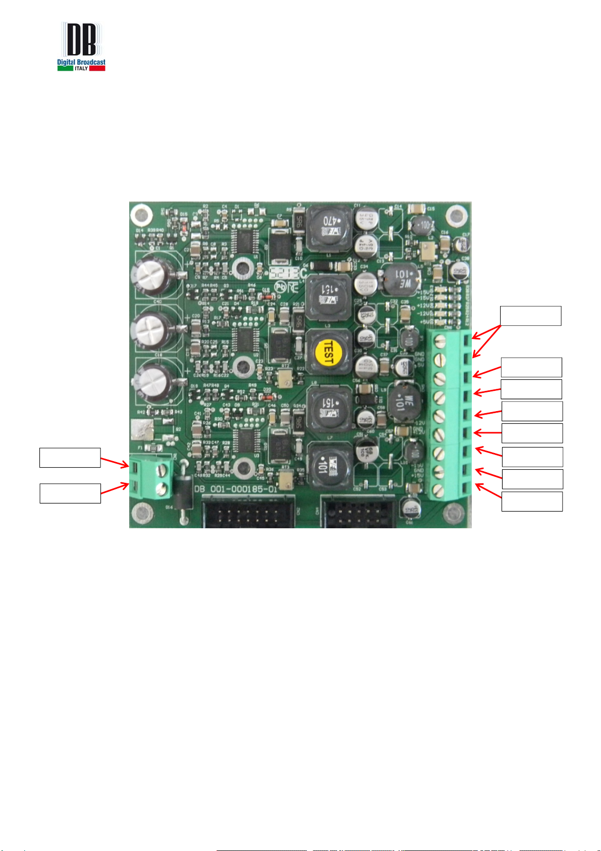
001-000185-01 POWER SUPPLY BOARD
On the 001-000185-01 power supply board, check if:
a) the +44VDC input power is present
b) +15VDC, -15VDC, +12VDC, -12VDC and +5VDC output power are present.
Fig. 4 – 001-000185-01 DC-DC converter
+44VDC
GND
GND
+5VDC
-12VDC
GND
+12VDC
-15VDC
GND
+15VDC

Mozart series calibrating procedure 7 /19
STEP 3: PROGRAMMING THE BOARDS
Using a MPLAB ICD3 programmer, the user must:
a) program the firmware to 001-000167-02 board (MPX board)
b) program the boot loader to 001-000166-02 board (Control Board). The firmware of the
Control Board will be programmed later through the webserver.
To upgrade the firmware:
a) Copy the folder upgrade_Mozart in the local disk C:\
b) Install ICD3 and MPLAB in your computer as indicated in the instruction manual of ICD3
c) Connect the ICD3 programmer to an USB port of your PC and to the Mozart transmitter
connectors (see the photos here below). Program first the 001-000167-02 board and after the
001-000166-02 board.
Fig. 5 – MPX Board programmer connector Fig. 6 – Control Board programmer connector
d) Switch ON the Mozart (without output power)
e) Start MPLAB from your PC without inserting or modifying any value
f) Upload the firmware
g) Press any key to exit from the DOS window.

Mozart series calibrating procedure 8 /19
h) After the process is complete, switch off the Mozart amplifier and connect to it a 50ohm
load to output.
Fig. 7 – 50ohm load connection

Mozart series calibrating procedure 9 /19
STEP 4: RF POWER CHECK
a) On the 001-000181-01 board (PLL-VCO board) disconnect the RF output coax cable (SMB
connector) from the board.
b) On the rear of the amplifier, make a short circuit on the ENABLE connector
(INTERLOCK).
Fig. 8 – ENABLE short circuit (INTERLOCK)
Mozart series calibrating procedure 10 /19
RF AMPLIFIER MODULE
This step is only for Mozart 50, 150, 300, 500 and 1000.
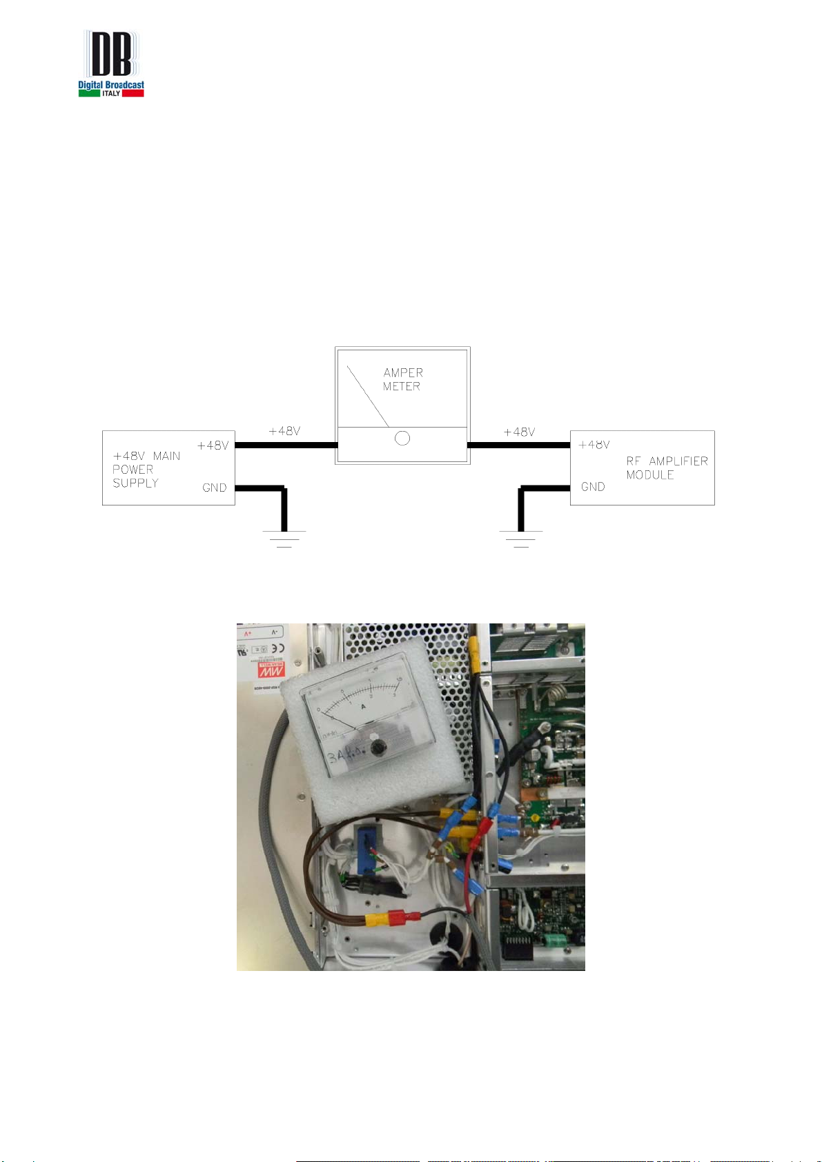
c) Disconnect the power cables from the RF amplifier module (pallet) which go to +48V main
power supply and connect an amper-meter in series.
Fig. 9 – Amper-meter diagram
Fig. 10 – Amper-meter in series
Mozart series calibrating procedure 11 /19
d) Switch on the amplifier and check on the front panel if the LED INTLCK is turned on. In
case of the led is turned off the short circuit on the ENABLE connector is missing.
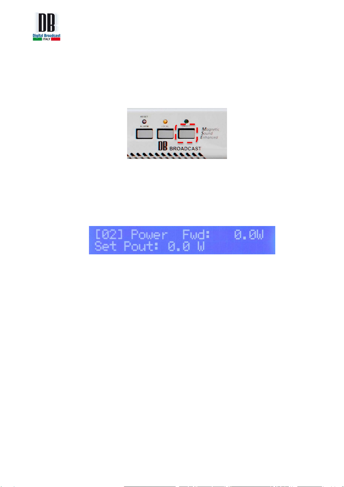
e) Press the RF ON/OFF button on the front panel to enable the RF. The green led near the
button will turn on.
Fig. 11 – RF ON/OFF button
f) On the LCD from the front panel go to menu “[02] Power FWD” and set the “Set Pout” to
the maximum value. Confirm the operation by pressing the OK button.
Fig. 12 – Set Pout menu
g) Set the trimmer on the “RF amplifier module” so as to obtain 200mA current absorption on
the amper-meter without the RF connected (see point a) of step 4).

Mozart series calibrating procedure 12 /19
Fig. 13 – 500W RF amplifier module Fig. 14 – 1KW RF amplifier module
30W RF DRIVER MODULE
The steps below are only for Mozart 500 and 1000 with the indicated values, for the other models
please see the table below with the right values of components.

Mozart series calibrating procedure 13 /19
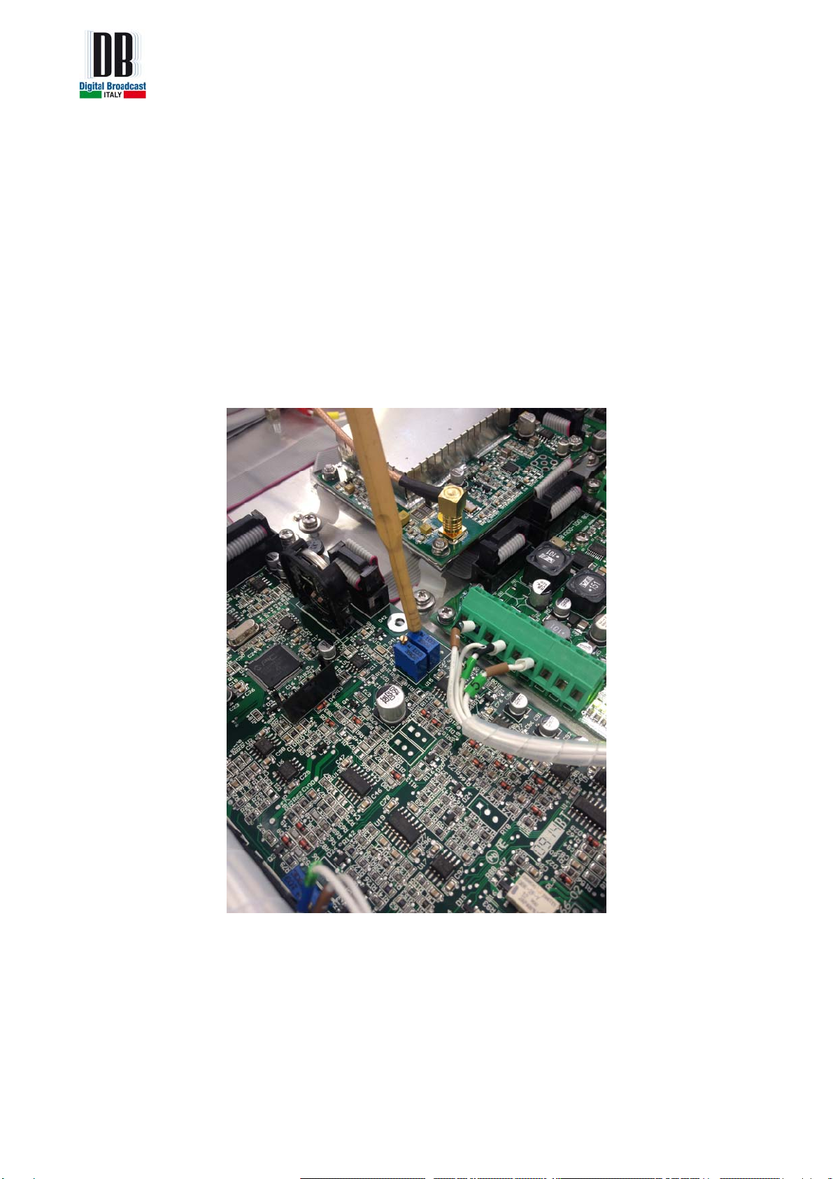
a) On the 001-000192-00 board, RT4 trimmer must be adjusted to have the maximum voltage
on the drain of the Q3 mosfet. The approximate voltage is 18.5V.
Fig. 15 – 30W RF module RT4 adjust
b) Adjust the RT2 trimmer to have a voltage drop of 20mV on the R22 resistor.
Fig. 16 – 30W RF module RT2 adjust
c) Adjust the RT1 trimmer to have a voltage drop of 10mV on the R36 resistor.

Mozart series calibrating procedure 14 /19
Fig. 17 – 30W RF module RT1 adjust
Table with R22 and R36 and Q3 values for each Mozart model.
R22 R36 Q3 drain
Mozart 30 100mV 20mV 26,5V
Mozart 50 80mV / 18.5V
Mozart 150 5mV 2,5mV 18,5V
Mozart 300 10mV 5mV 18,5V
Mozart 500 20mV 10mV 18,5V
Mozart 1000 20mV 10mV 18,5V
d) Press RF ON/OFF button on the front panel to disable the RF and switch off the amplifier.
e) Disconnect the amper-meter and reconnect the power cables to the RF amplifier module.
At this point the RF Power modules were calibrated successfully.
Mozart series calibrating procedure 15 /19
STEP 5: STARTING THE AMPLIFIER
a) Reconnect the COAX cable RF output on the 001-000181-01 board.
b) Switch on the amplifier and check if the “Set Pout” is set to maximum on the “[02]
Power Fwd” menu on the display. If not, set the output power to maximum.
c) Press RF ON/OFF button on the front panel to enable the RF.
d) On the 001-000166-02 board adjust the RT7 trimmer to set the maximum power of the
amplifier.
Fig. 18 – Control board RT7 adjust

Mozart series calibrating procedure 16 /19
CHECK FOR RF SPURIOUS AND HARMONICS
a) Press RF ON/OFF button on the front panel to enable the RF (if it’s disabled).
b) On the display go to Voltages and current page (by pressing down button) and control the
values of power consumption.
Fig. 19 – Voltage and current menu
c) Connect a spectrum analyzer to the amplifier and check for spurious and harmonics
if are within the limits.
d) Press RF ON/OFF button on the front panel to disable the RF.
Note: this procedure must be made for all frequency: 87.5MHz, 98MHz and 108MHz.
To change the frequency go to main “[01] Frequency” on the display, set the frequency and
confirm by pressing OK button.
e) After the procedure has been made for all frequency, set the frequency back to
98MHz.
SET THE FOLDBACK REFL AND REFL WARNING ALARMS
a) Go to “[02] Power Fwd” menu on the display and set the “Set Pout” to 25% of
maximum FWD power (ex: if Mozart 1000, set the Pout to 250W).
b) Go to “[07] Alarms” menu on the display and set the Foldback REFL to 100%.
Fig. 20 – Set Fold back REFL

Mozart series calibrating procedure 17 /19
c) Go to “[07] Alarms” menu on the display and set the REFL Warning to 100%.
Fig. 21 – Set REFL warning
d) Press RF ON/OFF button on the front panel to enable the RF.
e) Disconnect the 50ohm load from the rear of the amplifier.
f) On the 001-000166-02 board adjust the RT5 trimmer to set the reflected power at the
same value of the forward power (ex: FWD power: 250W = RFL power: 250W).
Fig. 22 – Control board RT5 adjust

Mozart series calibrating procedure 18 /19
g) On the front panel, adjust the RT1 trimmer up to see the “ALARM” led turns ON near
the display. The FWD power decreases to 0 and will try to increase automatically.
Fig. 23 – Control board RT1 adjust
NOTE: After 5 attempts to increase the FWD power, the amplifier will go in shutdown state.
The ALARM led near the button will turn ON and the RF ON led will be turned OFF. Press
RESET ALARM button to restore the normal function state of the amplifier.
Fig. 24 – Shutdown state LED turns ON
h) Switch off the amplifier and connect the 50ohm load to the output of the amplifier.
Alarm led
turns on RF ON/OFF
led turns off
Reset Alarm
Button

Mozart series calibrating procedure 19 /19
i) Switch on the amplifier and go to “[07] Alarms” menu on the display and set the FOLD
BACK REFL and the REFL Warning to 10%.
Fig. 25 – FOLD BACK REFL and REFL WARNING are set to 10%
j) Press RF ON/OFF button on the front panel to enable the RF.
k) Disconnect the 50ohm load from the output of the amplifier. The led WARNING will be
turned on. Check if the FWD power is 10% of “SET Pout”. (ex. The FWD power must
be 25W with WARNING turned on because before this we have set the FWD power to
250W. )
This manual suits for next models
6
Table of contents
Other DB Elettronica Telecomunicazioni Transmitter manuals


