DB Elettronica Telecomunicazioni KCL 30 SY User manual

DBELETTRONICA TELECOMUNICAZIONI S.p.A.
KCL 30 SY -FM broadcasting exciter/transmitter -USER’S MANUAL 1/37
KCL 30 SY
LCD FM Broadcasting Exciter/Transmitter
User’s Manual
Technical Diagrams
Release 1.1.0 BR
-DB ELETTRONICA TELECOMUNICAZIONI S.p.A. -
-Via Lisbona, 38 -35127 Z.I. SUD PADOVA ITALY-- Ph. (049) 870-0588 -Fax. (049) 870-0747 -
-http://www.dbbroadcast.com-

DBELETTRONICA TELECOMUNICAZIONI S.p.A.
KCL 30 SY -FM broadcasting exciter/transmitter -USER’S MANUAL
2/37
SAFETY NOTICES
WARNING
To avoid risks of electrical shocks or fire, only qualified personnel should execute the procedures
specified in this manual.
WARNING
When the protective covers of any device or component connected to a 110 / 240 VAC source by a
power cord are removed, voltages and currents dangerous to life may be exposed.
WARNING
Contact with 110 / 240 Volts of alternating current and associated direct current and voltages can be
fatal.
DANGEROUS
RISK OF ELECTRICAL SHOCK DO NOT OPEN
CAUTION
To reduce the risks of electrical shock, do not remove the cover (or the back). Refer, for servicing,
to qualified service personnel. This installation should be done by a qualified person and should
comply with to all local applicable laws.
NOTICE: ALL THE SPECIFICATIONS AND TECHNICAL INFORMATION IN THIS MANUAL ARE SUBJECT TO
CHANGE WITHOUT NOTICE.

DBELETTRONICA TELECOMUNICAZIONI S.p.A.
KCL 30 SY -FM broadcasting exciter/transmitter -USER’S MANUAL 3/37
INDEX
1. KCL 30 FM EXCITER/TRANSMITTER ...........................................................................................................................3
1.1 GENERALDESCRIPTION...............................................................................................................................................3
2. TECHNICAL SPECIFICATIONS ........................................................................................................................................3
3. INSTALLATION ........................................................................................................................................................................3
3.1 FREQUENCYSETTING....................................................................................................................................................3
4. SOFTWARE COMMANDS MAP.........................................................................................................................................3
4.1 MENU PASSWORD...........................................................................................................................................................3
4.1.1 GENERAL FUNCTIONS............................................................................................................................................3
4.1.2 PASSWORD MENU....................................................................................................................................................3
4.1.3 PUK MODE..................................................................................................................................................................3
5. ADJUSTMENTS AND MEASURES .....................................................................................................................................3
5.1 AFINPUTS ANDMAIN CARRIERDEVIATION.......................................................................................................3
5.2 SYSTEM CHECK................................................................................................................................................................3
6. POWER SUPPLY BOARD......................................................................................................................................................3
6.1 GENERALDESCRIPTION...............................................................................................................................................3
6.2 SWITCHINGMODULE PARTS LIST(DB 0206_090)...............................................................................................3
6.3 DB0201_070PRINTED BOARDPARTS LIST............................................................................................................3
7. SINTEL 96 MODULATION BOARD.................................................................................................................................3
7.1 GENERALDESCRIPTION...............................................................................................................................................3
7.2 SINTEL96PARTS LIST....................................................................................................................................................3
8. STEREO ENCODER BOARD........................................................ERRORE. IL SEGNALIBRO NON È DEFINITO.
8.1 CHANNELS PRE-EMPHASIS SETTING.........................................ERRORE.IL SEGNALIBRO NON È DEFINITO .
8.2 STEREO ENCODERPARTS LIST......................................................ERRORE.IL SEGNALIBRO NON È DEFINITO .
9. AMPLIFIER STAGE.........................................................................ERRORE. IL SEGNALIBRO NON È DEFINITO.
9.1 GENERALDESCRIPTION...................................................................ERRORE.IL SEGNALIBRO NON È DEFINITO .
9.2 AMP30 AMPLIFIERPARTSLIST ......................................................ERRORE.IL SEGNALIBRO NON È DEFINITO .
10. LCD GRAPHIC DISPLAY BOARD.........................................ERRORE. IL SEGNALIBRO NON È DEFINITO.
10.1 LCD GRAPHICDISPLAYBOARDPARTS LIST ...........................ERRORE.IL SEGNALIBRO NON È DEFINITO .
11. IN-AUDIO BOARD........................................................................ERRORE. IL SEGNALIBRO NON È DEFINITO.
11.1 IN-AUDIO BOARDPARTS LIST........................................................ERRORE.IL SEGNALIBRO NON È DEFINITO .
11.2 IN-AUDIO BOARDJUMPERS SETTING.........................................ERRORE.IL SEGNALIBRO NON È DEFINITO .
12. L.P.F. AND DIRECTIONAL COUPLER................................ERRORE. IL SEGNALIBRO NON È DEFINITO.
12.1 L.P.F. ANDDIRECTIONALCOUPLERPARTSLIST ...................ERRORE.IL SEGNALIBRO NON È DEFINITO .
13. APPENDIX A...................................................................................ERRORE. IL SEGNALIBRO NON È DEFINITO.
13.1 XLRAUDIO CONNECTORS PINOUTS ...........................................ERRORE.IL SEGNALIBRO NON È DEFINITO .

DBELETTRONICA TELECOMUNICAZIONI S.p.A.
KCL 30 SY -FM broadcasting exciter/transmitter -USER’S MANUAL
4/37
1. KCL 30 SY FM EXCITER / TRANSMITTER
1.1 GENERAL DESCRIPTION
The KCL 30 SY is a FM broadcasting exciter/transmitter that has a continuous variable
0÷30 W output power, adjustable by external control (see Chap.4).
The output frequency range is 87.5 -108 MHz with a 10 KHz step internal frequency
programmability (see Chap.4).
The /S option is characterized by an excellent built-in digital stereo coder with stereo
separation ≥65 dB and signal/noise ratio ≥80 dB.
The /R option indicates the presence of fully remote control capability with remote
adjustment and check of all the main parameters. Output power adjustment, power on/off
switch, protections reset, forward and reflected power measure, frequency deviation
measurement and control, alarm status are among the main possibilities of the remote
control option.
The exciter / transmitter has a high frequency stability, thanks to a Digital Phase Locked
Loop system and a very low drift EXTERNAL reference DISCIPLINED by GPS.
An internal deviation limiter controls the maximum frequency deviation avoiding the
interference of adjacent channels in case of accidental over modulation, but in order to
limit the over modulation it’s necessary to insert the jumper jp6.
An interesting feature of the KCL 30 SY exciter / transmitter is an intelligent protection
against load mismatching (VSWR).
Every alarm signal is displayed by front panel LEDS.
The metering front panel bar together with led indicators allows all the main parameters
and operating conditions to be completely and easily checked. In fact, output power,
reflected power, voltage supply for the power amplifier, frequency deviation, L & R and
MPX can be continuously verified using the front panel meter.
Front panel adjustment, output power setting (PWR adj.), frequency deviation (DEV adj.),
frequency transmission, manual/remote control selection (/R option) and mono/stereo
selection (/S option) are among the operations that can be performed.
An output low-pass filter ensures a pure RF spectrum, according to international requirements.
High-efficiency switching-mode power supply provides higher reliability and reduces
power consumption. Battery operation is also available as an option (/VDC).

DBELETTRONICA TELECOMUNICAZIONI S.p.A.
KCL 30 SY -FM broadcasting exciter/transmitter -USER’S MANUAL 5/37
Fig. 1.1 -KCL 30 FRONT VIEW
Fig. 1.2 -KCL 30 REAR VIEW
DBELETTRONICA TELECOMUNICAZIONI S.p.A.
KCL 30 SY -FM broadcasting exciter/transmitter -USER’S MANUAL
6/37
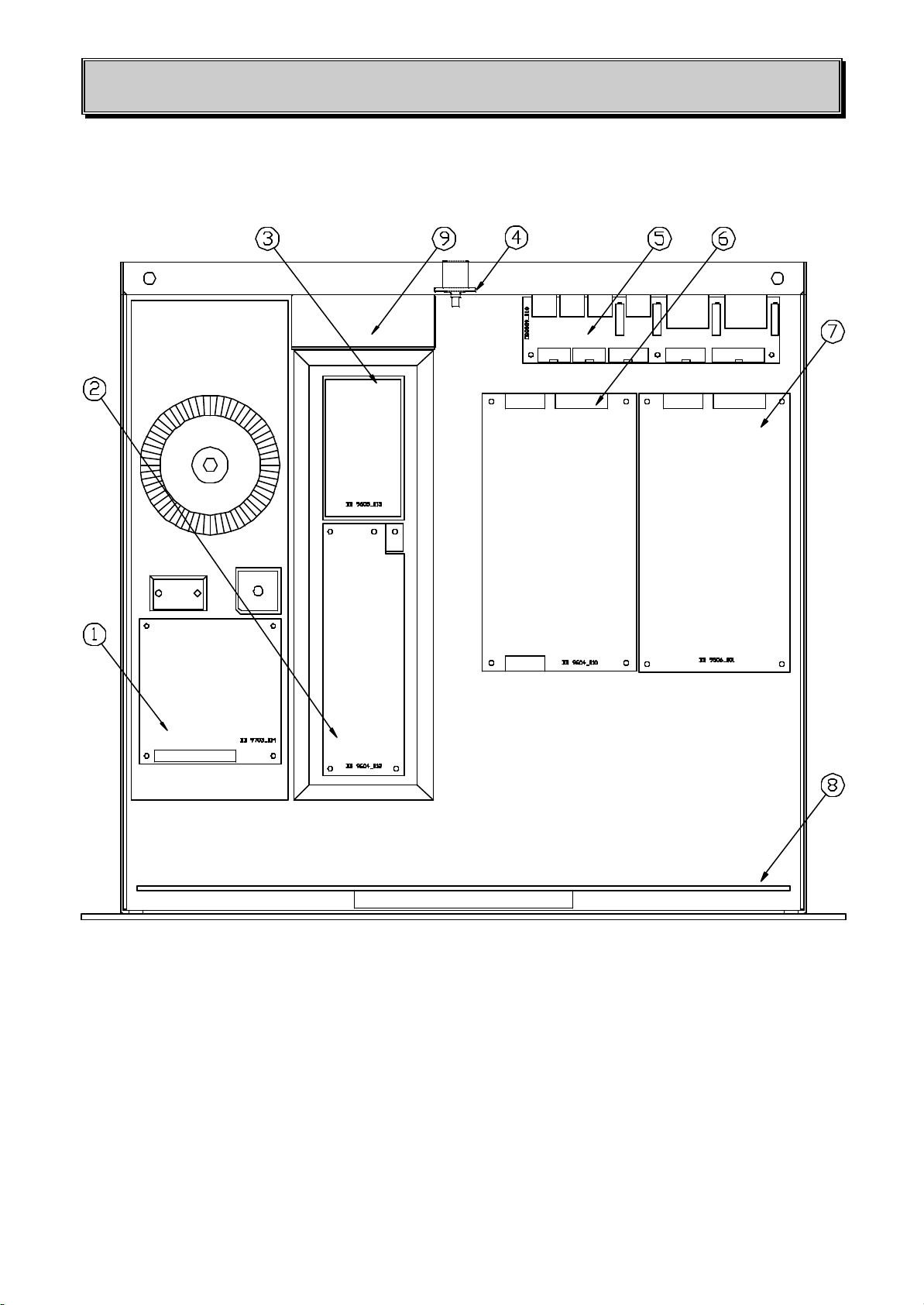
Fig. 1.3 -KCL 30 TOP VIEW
1) Power supply board 5) IN-Audio board
2) 30W (AMP30) Amplifier board 6) Sintel 96 Modulation board
3) L.P.F. and Dir. Coupler board 7) Stereo Encoder board
4) RF Output 8) Frontal LCD board
9) Fan

DBELETTRONICA TELECOMUNICAZIONI S.p.A.
KCL 30 SY -FM broadcasting exciter/transmitter -USER’S MANUAL 7/37
2. TECHNICAL SPECIFICATIONS
DATA
Output frequency range.................................................................................................87.5 -108 MHz
Output frequency setting synthesized with a 10 kHz step PLL
Output impedance ..........................................................................................................................50 Ω
Output connector................................................................................................................................. N
Continuous output power.....................................................................0÷30W continuously adjustable
Frequency stability
Thermal drift (0 ÷50 °C).........................................................................................................±250 Hz
Ageing drift ......................................................................................................................±250 Hz/year
Harmonics ............................................................................................................................... ≤-68 dBc
Spurious ....................................................................................................................................≤-80 dB
Syncro AM modulation.............................................................................................................≤-55 dB
Asyncro AM modulation..........................................................................................................≤-60 dB
MODULATION DATA
Mono operation
Input level -6 -+10 dBm
Input connector ............................................................................................................... XLR balanced
Input impedance...........................................................................................................................600 Ω
Bandwidth (± 0.25 dB)...................................................................................................20 Hz -15 kHz
Attenuation of frequency ≥19 kHz.............................................................................................≥50 dB
Preemphasis ..........................................................................................................................50/75 µsec
S/N ratio (± 75 kHz peak dev. with 1 kHz input, 50µs deemph.)...............................................≥80 dB
THD+N (± 75 kHz peak dev. with 1 kHz input, unweighted).....................................................≤0.1%
Stereo operation (with a stereo coder included in the /S model)
L & R / L & R input level................................................................................................-6 -+10 dBm
Input connectors.............................................................................................................. XLR balanced
Input impedance ..........................................................................................................................600 Ω
Bandwidth (± 0.25 dB)...................................................................................................20 Hz -15 kHz
Attenuation of frequency ≥19 kHz.............................................................................................≥50 dB
Preemphasis ..........................................................................................................................50/75 µsec
S/N ratio (± 75 kHz peak dev. with 1 kHz input, 50µs deemph)................................................≥73 dB
THD+N (± 75 kHz peak dev. with 1 kHz input, unweighted).....................................................≤0.1%
Stereo separation.................................................................................................... ≥55 dB (typ. 60 dB)

DBELETTRONICA TELECOMUNICAZIONI S.p.A.
KCL 30 SY -FM broadcasting exciter/transmitter -USER’S MANUAL
8/37
Stereo operation (with an external stereo coder)
MPX input level..............................................................................................2.2 Vpp per 75 kHz dev.
Input connector .............................................................................................................................BNC
Input impedance..........................................................................................................................10 KΩ
Bandwidth (± 0.25 dB).................................................................................................20 Hz -100 kHz
POWER REQUIREMENTS
Operating voltage ..................................................................................115/230 Vac ± 10 %, 50/60 Hz
Power consumption (at 25W output) ...........................................................................................50 VA
Battery operation (optional)........................................................................................................12 Vcc
OTHER CHARACTERISTICS
Operating conditions
Cooling system.............................................................................................air forced, 12Vcc axial fan
Temperature range ........................................................................................................... -10°-+45°C
Humidity................................................................................................................................ 95% max.
Weight and dimensions .......................................................................8 kg, 19' 2U, 483x430x90 mm
Options
Stereo coder (/S)
Remote control (/R)
Battery operation (/VDC)

DBELETTRONICA TELECOMUNICAZIONI S.p.A.
KCL 30 SY -FM broadcasting exciter/transmitter -USER’S MANUAL 9/37
3. INSTALLATION
The list below describes the basic steps for installing a KCL 30 SY exciter / transmitter.
1-Check that the ON/OFF switch on the rear panel is in OFF position.
2-Check that the internal setting of the main supply voltage on the rear panel is correct (110
or 220V).
3-Connect an antenna or a dummy load to the RF output connector on the rear panel.
4-Connect the transmitter to the mains power supply (110 –220V).
5-Switch ON the exciter/transmitter.
On the front panel you will see the “ON” led lit, and some seconds later the “LOCK” led lit too.
Select if necessary on back panel internal / external frequency REF.
6-Select by front panel push-button the forward power measurement.
7-Adjust the output power by means of the push-buttons, checking the front panel LCD display.
3.1 FREQUENCY SETTING
(see Chap.4)
Before changing the frequency of the exciter/transmitter lower the output power to its minimum
level.
Changing the frequency is very quick using the push-buttons and checking the LCD display on the
front panel of the KCL 30 SY.
When the frequency is at the desired value adjust the output power using the right push-button on
the front panel of the exciter/transmitter.
DBELETTRONICA TELECOMUNICAZIONI S.p.A.
KCL 30 SY -FM broadcasting exciter/transmitter -USER’S MANUAL
10 /37
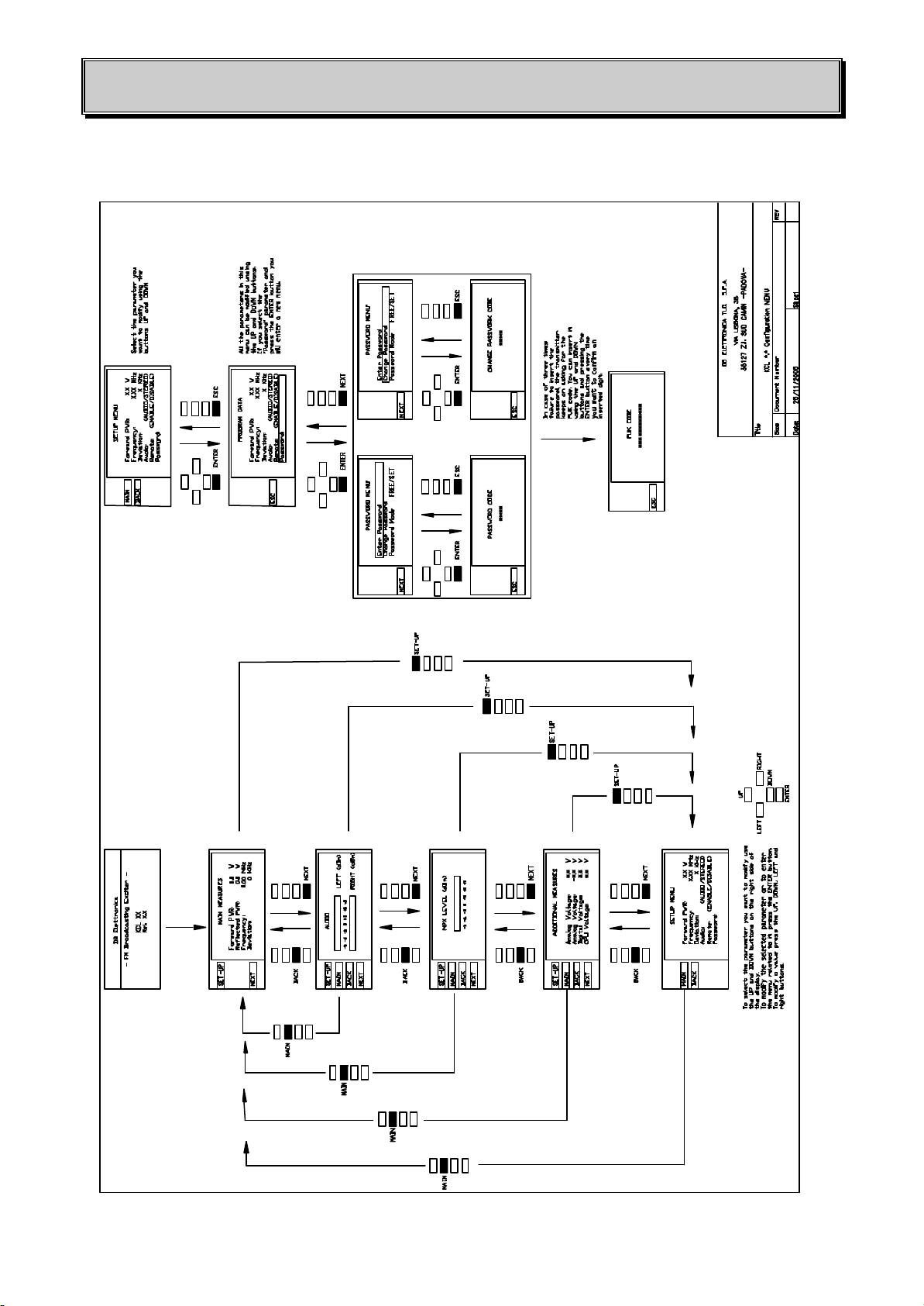
4. SOFTWARE COMMANDS MAP

DBELETTRONICA TELECOMUNICAZIONI S.p.A.
KCL 30 SY -FM broadcasting exciter/transmitter -USER’S MANUAL 11 /37
4.1 MENU PASSWORD
4.1.1 GENERAL FUNCTIONS
The transmitter is generally protected by a password that has been factory adjusted by
default: “1234”.
It is possible to modify such password through the relevant menu “Password” (MAIN →SET-UP
→PASSWORD MENU)
4.1.2 PASSWORD MENU
This menu is composed of the following three parts:
-Enter password
-Change password
-Password mode
ENTER PASSWORD
Here it is possible to insert the system password in order to make the modifications of setup values.
Once the password is correctly inserted, the system will be free for 30 minutes, after this time you
will need to repeat the password one more time.
WARNING
Ifa wrong password were inserted for more than three times, the system will go in PUK mode.
CHANGEPASSWORD
Here it’s possible to change the system password.
Password can be changed when the system is in Free mode only. (a password had already been
previously inserted). After the change you will go back to SETUP menu.
In case the right password has not been correctly inserted before, by entering this menu the
equipment will require the 1st password and in a second time will go back to SETUP menu; only in
this way you will be able to change the password .

DBELETTRONICA TELECOMUNICAZIONI S.p.A.
KCL 30 SY -FM broadcasting exciter/transmitter -USER’S MANUAL
12 /37
WARNING
In case a wrong password is inserted for more than three times, the system will go in PUK mode.
PASSWORD MODE
Here it’s possible to predispose the system for a safe mode, always free.
Set Mode
Trough this option the system asks for the password every time it is required (change of set-up
values)
Free Mode
The system is free and the password will never be requested.
WARNING:
When the transmitter enters this mode, it remains like this even in case of a power lack.
To pass from SET to FREE you need to insert password. On the contrary, the passage from FREE
to SET is immediate.
DBELETTRONICA TELECOMUNICAZIONI S.p.A.
KCL 30 SY -FM broadcasting exciter/transmitter -USER’S MANUAL 13 /37
4.1.3 PUK MODE
This one is a security mode. In case of three times failure to insert the password, the transmitter
keeps on asking for the PUK code.
Once the PUK code is inserted, the password will assume the default value: “1234”.
WARNING:
Turning off the transmitter won’t bring to PUK mode.
To obtain the PUK code please contact DB Elettronica’s technical service.
PUK code
……………………

DBELETTRONICA TELECOMUNICAZIONI S.p.A.
KCL 30 SY -FM broadcasting exciter/transmitter -USER’S MANUAL
14 /37
5. ADJUSTMENTS AND MEASURES
5.1 AF INPUTS AND MAIN CARRIER DEVIATION
For Left and Right input signals (KCL 30 SY /S), use the corresponding female XLR connectors on
the rear panel. The input impedance is 600 Ω.
Adjusting the input trimmers, the transmitter can accept input signal levels ranging from about -6
dBm to +10 dBm with 75 kHz peak deviation.
For a Mono input signal (a KCL 30 SY no stereo generator inside), the input female XLR connector
can accept the same input signal levels as the aforementioned Left and Right signals.
For a MPX input signal (a KCL 30 SY no stereo generator inside) the input BNC connector (10 kΩ
input impedance) can accept input signal levels ranging from -3 dBm to +3 dBm with 75 KHz peak
deviation.
For SCA signals (>53 kHz), use the input BNC connectors (1 kΩinput impedance).
The SCA input level for a correct deviation of the main carrier (≈1.25 KHz peak) is
about 0.3 Vpp.
To adjust the peak deviation of the main carrier, use the push-buttons and the LCD grafic display on
the front panel.
5.2 SYSTEM CHECK
On the front panel a section labelled “STATUS” allows the main functions and the protections of
the exciter/transmitter to be monitored.
⇒The “LOCK” led light shows the correct lock of the frequency synthesis circuit on the
modulator board.

DBELETTRONICA TELECOMUNICAZIONI S.p.A.
KCL 30 SY -FM broadcasting exciter/transmitter -USER’S MANUAL 15 /37
⇒The “STEREO” led light shows the use of the internal stereo generator board (if there is).
The mono signal is obtained by the sum of the left and right signals for the KCL 30 SY /S.
If there is not the stereo generator board, the STEREO LED are not used.
⇒The “ON” led light (Fig. 1.1) shows that the power of the exciter/transmitter is on and so the
MAIN POWER SUPPLY is.
⇒The “ALARM” led light (Fig. 1.1) shows that the VSWR protection is fully operative.
Such intelligent protection is characterized by an automatic reset circuit of about 2-3 second delay
to avoid risks of accidental intervention.
⇒The “REMOTE” led light (Fig. 1.1) shows that the remote control option is activated.
If there is not the stereo generator board, the REMOTE LED are not used.

DBELETTRONICA TELECOMUNICAZIONI S.p.A.
KCL 30 SY -FM broadcasting exciter/transmitter -USER’S MANUAL
16 /37
6. POWER SUPPLY BOARD
6.1 GENERAL DESCRIPTION
The KCL 30 SY power supply is composed of the following elements:
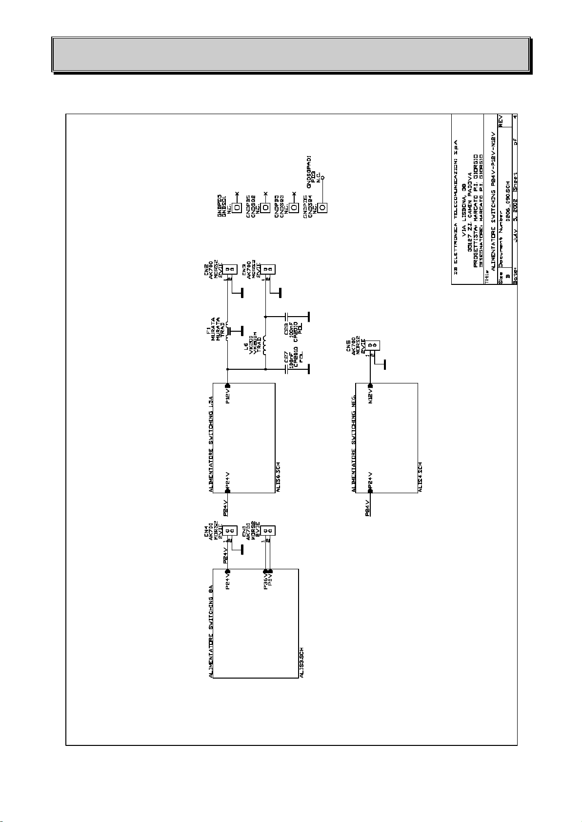
•1 switching module (Fig. 6.1) capable of ±12 VDC (6A max) and +24 VDC (10A max) to
power supply the Protection and frontal boards, Sintel GHz modulator board, Amplifier board and
all optional boards present .
•1 toroidal transformer
WARNING: before substituting one or more broken switching module it is necessary to disconnect
its output and to set the output voltage, without any load, at the right value (22.5v ±2%) before
reconnecting the switching module output to the other circuits and boards in order to avoid
overvoltage problems.
The switching-mode power supply provides:
1. the efficiency is 80% higher hence provides a considerable reduction of the internal heating,
thus simplifying the cooling system;
2. alower thermal and mechanical stress for associated components, such as transformer, diodes,
rectifier bridges is inflicted;
3. the power supply voltages at the output of the switching regulators are constant even in case
of wide main fluctuations (±15 %).
DBELETTRONICA TELECOMUNICAZIONI S.p.A.
KCL 30 SY -FM broadcasting exciter/transmitter -USER’S MANUAL 17 /37
Fig. 6.1 -SWITCHING MODULE GENERAL ELECTRICAL SCHEMATIC (DB 0206_090)

DBELETTRONICA TELECOMUNICAZIONI S.p.A.
KCL 30 SY -FM broadcasting exciter/transmitter -USER’S MANUAL
18 /37
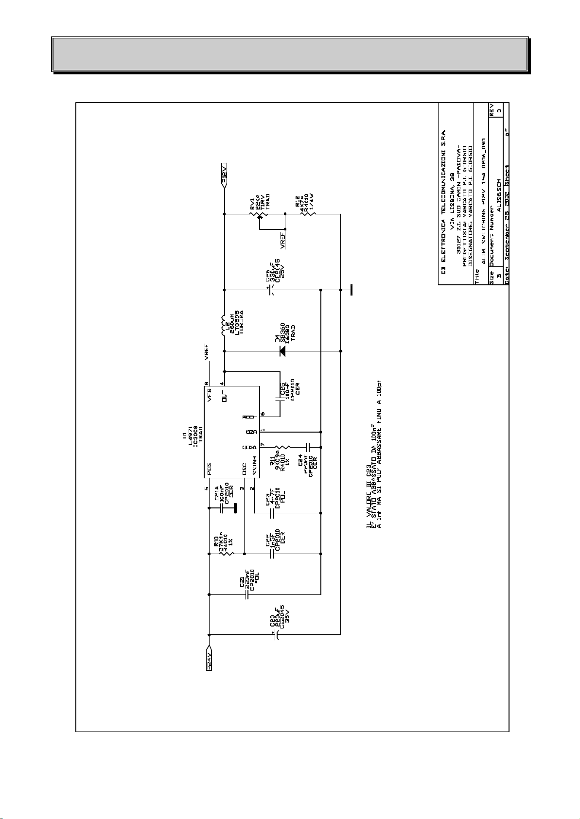
Fig. 6.2 -ELECTRICAL SCHEMATIC (+24 V) SWITCHING MODULE (DB 0206_090)

DBELETTRONICA TELECOMUNICAZIONI S.p.A.
KCL 30 SY -FM broadcasting exciter/transmitter -USER’S MANUAL 19 /37
Fig. 6.3 -ELECTRICAL SCHEMATIC (-12 V) SWITCHING MODULE (DB 0206_090)
DBELETTRONICA TELECOMUNICAZIONI S.p.A.
KCL 30 SY -FM broadcasting exciter/transmitter -USER’S MANUAL
20 /37
Fig. 6.4 -ELECTRICAL SCHEMATIC (+12 V) SWITCHING MODULE (DB 0206_090)
Table of contents
Other DB Elettronica Telecomunicazioni Transmitter manuals


