LOWBATTERYINDICATIONSIGNALLING
INSTALLATIONCONSIDERATIONS
OPERATINGCONSIDERATIONS
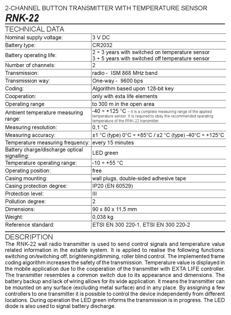
Duringnormaloperation,lowbatteryisindicatedbytheSTA-
TUS LED ashing quickly several times when a button is
pressedandreleasedtotransmit.Ifthetransmitterhasbeen
pairedwithanEXTALIFEcontroller,lowbatterystatusisalso
indicatedbytheEXTALIFEmobileappwiththeBattery:Low
message(seegure).Thetransmitterwillindicatethatthebat-
teryhastobereplaceduntilthebatteryvoltagedropsto<2.1
V.Thelowbatteryindicationstopsonlywhenthebatteryhas
beenreplaced.
REPLACINGTHEBATTERY
1. Removethetwomountingscrewsofthelowercoverofthe
transmitter.
2. RemovethePCB.
3. Removethebatteryfromtheterminal(forexample:byusingaatscrewdriver).
4. Pressanybuttonconnectedtotransmitterinputsseveraltimes(thisistodrainanyresidualvolt-
age).
5. Installanewbattery.Mindthepolarity.Thepolarityismarkedonthebatteryclipterminal(the+
pole). CAUTION: Wrong battery polarity may damage the transmitter!
6. ReinsertthePCBintotheenclosureandscrewthelowercoverbackon.
7. Verifyproperoperation:theLEDshouldbeon,likewhentransmitting.
1. Ifpossible,maintainaminimumdistancebetweentransmittersduringinstallation.Inparticular,
avoidinstallingonetransmitteraboveanother.Insomesituations,thiscouldcauserangeloss
andtransmissionerrors.
2. Duringinstallationmakesurethatthetransmitterisnotexposedtodirectwaterimpactoropera-
tioninahighhumidityenvironment.Thetemperatureattheinstallationsiteshouldbefrom-10
to+55°C.
3. TheRNP-22transmitter isdesignedforindoor installation.Inthecaseofoutdoorinstallation,
placethetransmitter inanadditional sealingboxandefcientlysealtheconnectionagainst
waterpenetration.
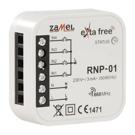
4. ConnectcontrolconnectorstoinputsIN1toIN4oftheRNP-22transmitter.Typically,theinputs
aredesignedtoworkwithmonostableconnectors.However,thedesignoftheinputsdoesnot
excludeusingbistableconnectors.Inthiscase,itisbesttoprogramtheinputswithareceiverin
monostablemode(thereceiverisactivatedaslongasthegiveninputistriggered).
5. After installing the transmitter, test it for proper operation. To obtain the target function, the
transmitter must rst be programmed with thereceiver(see the user manual ofthe selected
receiver).Toworkwiththecontroller,thetransmittermustbeproperlypairedwiththecontroller
(seeTransmitterregistrationintheEXTALIFEsystem).
STANDARD FUNCTIONALITY (WITHOUT CONTROLLER)
● enableswirelessoperationofEXTALIFEsystemreceivers,
● the function of each transmitter input depends on the type of receiver the inputs have been
pairedwith(example:ifpairedtoanROP-22receiver,theinputscanbeusedtoturnlightson
andoff;ifpairedtoanSRP-22controller,thebuttonscanopenandcloserollershutters),
● eachinputcanbeassignedtomultipleEXTALIFEsystemreceivers,
● ifoneinputistocontrolmorethanonereceiverofthesystem,thentherecommendedmodeof
operationis“on/off”mode(forexample:input“1”turnsonthereceiverandinput“2”turnsitoff),
● youcanassignthetransmitterinputstoreceiverswithdifferentoperatingmodes,therangeof
which depends on the receiver type (for details ofthe modes see the applicable EXTALIFE
receiverusermanuals),
● If transmitter inputsareassignedto a receiver in timemode,eachbutton canbeassigneda
customtimevaluefrom1sto18hours,
● youcandeletespecicinputassignmentsfromthereceivermemory.
FUNCTIONAL COMPATIBILITY WITH EXTA LIFE CONTROLLER AND APP
WiththeEFC-01controllerandapp,youcan:
● remotely(withoutaccesstothereceiver)bindspecictransmitterinputstotheselectedreceiv-
ers,
● assignselectedtransmitterinputstoplayscenes,
● assignselectedtransmitterinputsasaconditiontoexecutealogicalfunction,
● signalthetransmitterbatterylevel.
Thesefunctionsareenabledonlyonatransmitterpairedwithacontroller.
OPERATION
Uponashortpressofabuttonconnectedtoagiveninput,thetransmittersendsanRFcommand
totheEXTALIFEsystemcomponents.Informationtransmissionissignalledbythegreen“Status”
LEDblinking.Toproperlyinterpretthesignalfromthegiventransmitterinput,thetransmittermust
rstbepairedwithit.SeetheapplicableEXTALIFEreceiverusermanualsforpairinginstructions
(programmingspecicinputs inthe receiver memory).The transmitter willonlytransmitwhena
buttonconnectedtoagiveninputispressedandthenreleased.NoRFsignalistransmittedaslong
asabuttonisheldpressed.RNP-22transmitterinputsarenotblocked.Thismeansthatifagiven
inputistriggeredcontinuously,thentheotherinputsworkaccordingtothetransmitterspecication.
The presented mode of operation translates to transmitter functionality with traditional bistable
connectorsconnectedtoinputsIN1…IN4.Forexample,iftheconnectorconnectedtoinputIN1is
towork withareceiverin“bistable”mode,theconnectormustbeclosedto activatethereceiver.
However,tore-activatethereceiver(ifithasbeenturnedoff,forexamplewitharemotecontrol),rst
openandclosetheconnectoragain.
Low battery indication in the
EXTA LIFE app
