ASTECH TX31D/1/IFM User manual

ASTECH ELECTRONICS LIMITED
OPERATING INSTRUCTIONS
SINGLE CHANNEL ‘D’ RANGE
ROTARY/SHORT RANGE TELEMETRY EQUIPMENT
©
Astech Electronics Ltd
Reproduction of any written material or illustration in this publication
in any form or for any purpose is expressly forbidden
unless the prior consent of Astech Electronics Limited has been given in writing
Forge Industrial Estate, BINSTED, Alton, Hampshire GU34 4PF, England.
Tel: 01420 22689, Fax: 01420 22636
Via Paolo Uccello 4 - 20148 Milano
Tel +39 02 48 009 757 Fax +39 02 48 002 070
[email protected] www.dspmindustria.it

TM Page 2

TM Page 3
CONTENTS
1ASTECH ROTARY TELEMETRY SYSTEMS - GENERAL DESCRIPTION 5
2LIST OF SYSTEM ITEMS & SERIAL NUMBERS 6
3Transmitters 7
3.1 Transmitter TX31D/1/IFM 7
3.1.1 TX31D/1/IFM Input Connections & Scaling 8
3.1.2 TX31D/1/IFM Calculation of Shunt Calibration Resistor "Rcal" 9
3.1.3 TX31D/1/IFM Mounting and Cover Plate 9
3.1.4 TX31D/1/IFM Specifications 10
3.2 Transmitter TX34/1/IFM 11
3.2.1 TX34D/1/IFM Input Connections & Scaling 12
3.2.2 TX34D/1/IFM Calculation of Shunt Calibration Resistor "Rcal" 12
3.2.3 TX34D/1/IFM Mounting and Cover Plate 12
3.2.4 TX34D/1/IFM Specifications 13
3.3 Transmitter TX35/1/IFM 14
3.3.1 TX35D/1/IFM Input Connections & Scaling 15
3.3.2 TX35D/1/IFM Calculation of Shunt Calibration Resistor "Rcal" 15
3.3.3 TX35D/1/IFM Specifications 15
4DEMODULATOR RE3D 16
4.1 RE3D Front and Rear Panels 16
4.2 RE3D Controls & Connections 18
4.2.1 RE3D Specifications 18
4.3 RE3D Programing 20
4.3.1 Programming Notes 20
4.3.2 Setting the Display Resolution 21
4.3.3 Program Flow Charts 21
4.3.3.1 RE3D With TX34D Transmitter 22
4.3.3.2 RE3D With TX31D Transmitter 23
4.3.4 RE3D Programming Menu 24
4.3.5 Display Menu 24
4.3.6 Analogue Outputs Menu 24
4.3.7 Trim Adjust Menu 25
4.3.7.1 Strain Zero trim 25
4.3.7.2 Strain Gain trim 25
4.3.8 Strain Display Menu 25
4.3.8.1 Strain Units 25
4.3.8.2 Strain scaling 25
4.3.9 Strain Transmitter Setup 25
4.3.9.1 Input type 25
4.3.9.2 Transducer mV/V 26
4.3.9.3 µεFull Scale 26
4.3.9.4 Calculated Gain 26
4.3.9.5 Calibration Resistor 26
4.3.9.6 Gauge Setup 26
4.3.9.7 Shaft Size 26
4.3.9.8 Shaft Material 26
4.3.10 TXxx Control 27
4.3.10.1 TX34 Calibration Mode 27
4.3.10.2 TX34 Zero Adjust 27
4.3.10.3 TX34 Input Invert 27
4.3.10.4 Show TX34 Setup 27

TM Page 4
4.3.11 Tachometer Settings Menu 27
4.3.11.1 Set the Number of Tachometer Flags 27
4.3.11.2 Set the Full Scale RPM 27
4.3.12 Decoder Settings Menu 28
4.3.12.1 Set the transmitter type 28
4.3.12.2 Set the Output Calibration Mode 28
4.3.12.3 Set the OLED Display Brightness 28
5INDUCTIVE POWER SUPPLY & TRANSMITTER INSTALLATION 29
5.1 Inductive Head IH2 or IH2/L with shaft mounted power pickup loop 30
5.1.1 Inductive Head IH2 or IH2/L with Power Pickup Loop in Split-Ring Assembly "TX.MTGS" 30
5.1.2 Suggested Installation for Inductive Head IH2-IH2/L with Power Pickup Loop in Split-Ring
Assembly31
5.1.3 Inductive Head IH2 or IH2/L with Power Pickup Loop Wound onto Shaft Using CAK Kit 32
5.1.4 Suggested Installation Sequence for Inductive Head IH2 or IH2/L with Transmitter & Power
Pickup Loop Using CAK Kit: 32
5.2 Inductive Loop IL2 with shaft mounted power pickup loop or ip2 pickup 33
5.2.1 Inductive Loop IL2 with Power Pickup Loop in Split Ring Assembly "TX.MTGS" 33
5.2.2 Suggested Installation Sequence for Inductive Loop IL2 with Power Pickup Loop Integrated in
Split-Ring Assembly 34
5.2.3 Inductive Loop IL2 with Power Pickup Loop Wound onto Shaft Using CAK Kit 35
5.2.4 Suggested Installation Sequence for Inductive Loop IL2 with Transmitter & Power Pickup Loop
on Shaft Using CAK Kit: 36
5.2.5 Inductive Loop IL2 with Inductive Power Pickup IP2 on Shaft Using CAK Kit 37
5.2.6 Suggested Installation Sequence for Inductive Loop IL2 with Transmitter & IP2 Power Pickup
on Shaft Using CAK Kit: 39
6SYSTEM CHECKOUT 39
6.1 Non-Operation 40
6.2 Improving Efficiency of Inductive Power Supply 40
6.3 Attaching transmitter/IP2 pickup module on small diameters 41
6.4 Dimensioned drawings of IH2 & IL2 42

TM Page 5
1 ASTECH ROTARY TELEMETRY SYSTEMS - GENERAL DESCRIPTION
Astech Rotary Telemetry Systems enable the measurement of physical quantities – torque, strain,
temperature or vibration for example, on rotating or moving components, by means of non-contacting radial
data transmission. In addition to providing a wire-free method of transferring the measurement data to a
stationary pickup, the systems incorporate signal conditioning for the component mounted transducers, and
outputs in either analogue or digital serial formats.
The telemetry system is based around the RE3D Demodulator. This is a highly sophisticated unit that can output digital and
analogue data collected from a variety of transmitter types. The built in microcontrollers allow onboard computation of
strain and power directly from mechanical parameters entered into the unit from the front panel or using a PC/laptop via a
USB interface. Circuitry and hardware comprising of a demodulator, pcm decoder and analogue output conditioning circuitry
– digital zero and output level trimmers, signal status indicators etc., are contained within a compact extruded aluminium
enclosure type RE. An inductive power supply oscillator, which replaces batteries as the transmitter power source, is also
incorporated. This can be disabled allowing battery powered transmitters to be used. The power supply is highly flexible
allowing the unit to be powered by either a 9-30VDC source at 1A or a 90-260VAC mains voltage.
Output conditioning circuitry provides filtering, zero adjustment and output level adjustment. Maximum output levels are ±
10V. A tachometer input allows shaft RPM to be displayed. Valid data reception is indicated by the presence of a front
panel red ‘Error’ LED. Depending on the transmitter type various signals can be output. For example, using a TX34D or
TX35D allows the display and output of strain, power, and transmitter power supply voltage and transmitter temperature.
The new programmable transmitters, eg TX34D/TX35D, allow the RE3D to be used to set the gain, offset and calibration.
This is done by sending commands via the inductive power supply to the microcontroller on the transmitter. This allows the
gain offset and calibration to be controlled whilst the transmitter is installed.
The received data is decoded into analogue
voltage outputs, or alternatively converted to
serial data for input into a PC. Various types
of demodulator/readout hardware are
available, including benchtop, industrial and
compact versions for in-vehicle use.
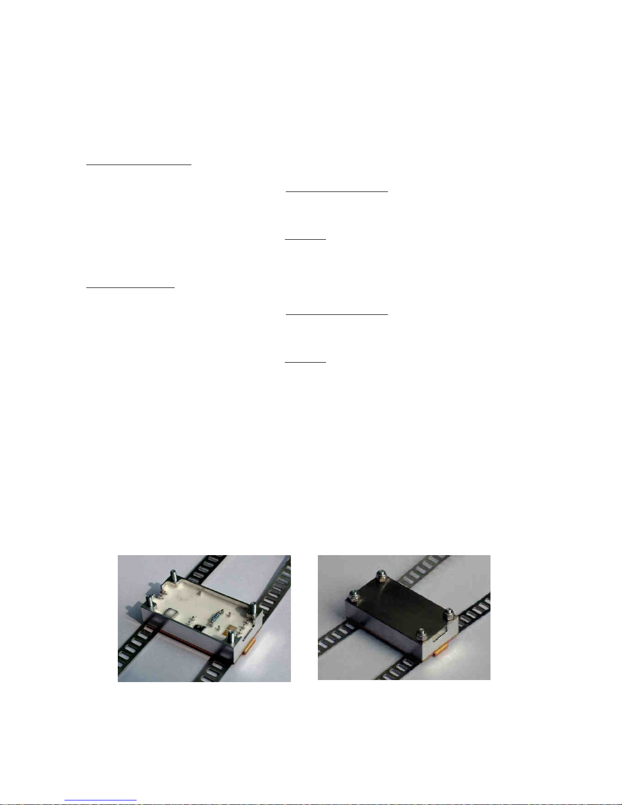
A miniature transmitter and power pickup
loop or battery pack are attached to the
rotating shaft or component. The
transmitter converts the transducer
outputs into a frequency modulated signal,
enabling transfer from the rotating shaft to
a stationary pickup. The standard
transmission method is by inductive-
coupling, but alternatives including infra-
red, radio and capacitive coupling are also
available for special applications.
A pickup, combined with an
energising head in the case of
inductively powered systems,
collects the data and re-
transmits via cable to the system
demodulator and readout
hardware.
769

TM Page 6
2LIST OF SYSTEM ITEMS & SERIAL NUMBERS
(Example)
1 x Transmitter Type TX34D/1/IFM (1 Strain Input Channel and Supply V Monitor Channel) plus Screening Cover &
CAK Mounting Baseplate S/No. 3203
1 x CAK Shaft Mounting Kit
1 x Inductive Power Supply/Signal Pickup Head Interface Module IH2 S/No. 3205
1 x Mounting Bracket for Inductive Head & Loop Interface Module.
1 x 5 Metre Co-axial Connecting Cables terminated with TNC Plugs.
1 x RE3D/IFM/1 Single Channel Demodulator/Decoder plus 3 Pin Input Power Connector. S/No. 3204
1 x Operating Instructions + Drawings of TX31D, IH2 & IL2

TM Page 7
3 TRANSMITTERS
3.1 TRANSMITTER TX31D/1/IFM
The single channel (plus power supply monitor channel) TX31D/1/IFM transmitter is a compact, low profile design, used
when a minimum diameter for the shaft mounted hardware is required. The lightweight machined aluminium housing is
drilled to accept a screening cover and slotted base-plate fixture (for use with the shaft clamp assembly kit CAK). Power
supply is normally by inductive coupling into a single turn pickup loop, either wound around the shaft periphery (and
separated from the shaft by an insulating standoff layer), or located within a groove machined into the split-ring assembly
O.D. The transmitter may also be powered by batteries. For example, two ½ AA size lithium cells usually housed within a
TX.MTGS split ring assembly, or the TX31 battery unit.
Circuitry consists of an input filter followed by an instrumentation amplifier, stabilised bridge excitation supply of 4.096VDC,
12 bit A/D converter plus control logic, rectification circuitry to convert the incoming AC inductive power to filtered DC (not
used if battery powered) and finally, a 10.7 MHz fm output stage. The input amplifier gain controls the overall system
sensitivity and is set by an external resistor "Rg", which is user fitted between two pins on the transmitter. A remote
calibration facility is incorporated into the input stage and is activated by temporarily interrupting the transmitter power
supply (i.e. turn off demodulator module power). When power is re-applied, a shunt calibration resistor is connected across
one arm of the strain gauge input circuit for a period of 10 seconds. The shunt calibration resistor is user fitted across two
solder pins.
Signal transmission is by inductive coupling of the 10.7MHz f.m. carrier from a single-turn loop wound around the shaft (in
an inductively powered system this loop also collects power) and an inductive head IH1 (IH2 or inductive loop IL2 for
inductively powered transmitters). Transmission range is typically 50-200mm, reducing to 10-15mm for inductively powered
transmitters, this being the maximum airgap across which sufficient electrical power for the transmitter can be transferred.
In construction, the transmitter circuitry is encapsulated in epoxy resin within a machined aluminium housing with solder
pins providing the input connections to the strain gauge leadwires, inductive power/pickup loop and sensitivity setting/shunt
calibration resistors. The transmitter housing is drilled with 4 x M3 clearance holes for attachment of the screening cover
and mounting baseplate.
P4
P3
P2
P1
P6
P5
P8
P7
P10
P9
P11
P13
P12
Figure 1 - TX310D/1/IFM Transmitter Connections
P1= 0V EX
P2= - SIG
P3= + SIG
P4= +4.096V EX
P5= R cal
P6= R cal
P7= R gain
P8= R gain
P9= +V IN
P10= 0V & HOUSING
P11= PCM TEST
P12= LOOP ANT
P13= LOOP ANT
IF THE TRANSMITTER IS CLOSE TO INDUCTIVE HEAD:
1) Use screened cable for gauge leads
2) Fit supplied metal cover to screen transmitter circuitry
3) Connect signal cable screen to transmitter housing
Failure to do this may result in a zero shift once per
revolution due to inductive power magnetic field pickup

TM Page 8
3.1.1 TX31D/1/IFM Input Connections & Scaling
Input sensitivity of the transmitter input is set by a resistor (Rg), which is soldered across pins P6 and P7. This sets the
gain of the input amplifier such that its output at (at full scale signal input) uses ±41.5% of the total A/D convertor range.
The remaining ±8.5% allows signal source offsets of up to ±20% of full scale to be within the dynamic range of the system
and thus removable at the demodulator/decoder unit (via the zero control).
From 1/1/2006 all transmitters have VEx increased from 4.096V to 5VDC. As the A/D converter uses VEx as a reference,
the input sensitivity equation is slightly altered. Equation for both version are listed below:
Transmitters with+ 4.096VEx
Rg is calculated from:
Alternatively:
Full Scale mV In is the mV output from the strain gauge bridge, transducer or other signal source.
In the case of a four arm fully active torsion bridge, the mV output for a given strain may be calculated from:
E = Strain in Microstrains
G.F. = Gauge Factor
4.096 = Bridge Excitation Voltage
Transmitters are usually shipped with Rg=100 ohms, giving a full scale input sensitivity of;
Transmitters with+5.0VEx
Rg is calculated from:
Alternatively:
Full Scale mV In is the mV output from the strain gauge bridge, transducer or other signal source.
In the case of a four arm fully active torsion bridge, the mV output for a given strain may be calculated from:
E = Strain in Microstrains
G.F. = Gauge Factor
4.096 = Bridge Excitation Voltage
Transmitters are usually shipped with Rg=100 ohms, giving a full scale input sensitivity of;
50,000 x Required Full Scale mV In
1,700 - Required Full Scale mV In
Rg (ohms) =
1,700 x Rg
50,000 + Rg
Full Scale Range in mV =
mV =
E x G.F. x 4.096
1,000
1,700 x 100
50,000 + 100
Full Scale Range in mV =
= ±3.393mV
50,000 x Required Full Scale mV In
2,075.2 - Required Full Scale mV In
Rg (ohms) =
2,075.2 x Rg
50,000 + Rg
Full Scale Range in mV =
mV = =
E x G.F. x 5
1,000
2,075.2 x 100
50,000 + 100
Full Scale Range in mV =
= ±4.142mV

TM Page 9
3.1.2 TX31D/1/IFM Calculation of Shunt Calibration Resistor "Rcal"
Two solder pins P5 and P6 are provided for the incorporation of a user fitted shunt calibration resistor (Rcal). When the
transmitter power supply is momentarily interrupted (and when the transmitter is first powered up), the micro-controller in
the transmitter switches the resistor between "0VEX" and "-SIG" pins for 10 seconds. This feature is mainly suitable for
inductively powered transmitters, since the inductive power may be interrupted whilst the shaft is rotating, providing a
"Remote Calibration" facility. Required value for the calibration resistor Rcal, may be calculated from:
Transmitters with 4.096VEx
For example;
Transmitters with 5VEx
For example;
3.1.3 TX31D/1/IFM Mounting and Cover Plate
The TX31D/1/IFM can be mounted on a plate surface by using M3 bolts through the 4 corner holes or it may be fixed
onto a shaft using the strapping attachment plate included in the CAK kit.
If the transmitter is inductively powered a mu metal cover plate may be required. This is necessary when the transmitter
is close to the pickup head IH2 or loop IL2. Failure to do this may result in a zero shift once per revolution, due to
inductive power magnetic field pickup.
To minimise noise levels and stray signal pickup;
1. Use screened cable for the strain gauge leads
2. Fit the supplied mu metal cover to screen the transmitter circuitry
3. Connect the signal cable screen to transmitter housing
4. Ground the transmitter to the shaft
1024 x Gauge Resistance
Required Signal in mV
Calibration Resistor in Ohms =
- (0.5 x Gauge Resistance)
1024 x 350
2 mV - (0.5 x 350)
Calibration Resistor in Ohms =
= 179,025 ohms
Figure 2 – TX31D with Strapping Plate and Mu Metal Cover
1250 x Gauge Resistance
Required Signal in mV
Calibration Resistor in Ohms =
- (0.5 x Gauge Resistance)
1250 x 350
2 mV - (0.5 x 350)
Calibration Resistor in Ohms =
= 218,575 ohms

TM Page 10
3.1.4 TX31D/1/IFM Specifications
Input: 1 channel full bridge strain gauge input. "Instrumentation Amp" input, operating at
2.048V common-mode (set by strain gauge bridge common-mode). Series and
common-mode input resistance 20 M ohms. Input bias current 1 nA. Input sensitivity
set by single user accessible resistor. Range 0.1 mV to 500 mV full scale.
Bridge Excitation Supply: 4.096VDC ±1% (5VDC from 1/1/2006) over full operating temperature range. Voltage
temperature coefficient typically 20 ppm / °C. Maximum bridge output current 40 mA.
Short circuit protected.
Zero Shift with Temperature: Typically 0.03 %/°C.
Resolution & Accuracy: 11 bits plus sign, 0.1% full range.
Operating Temperature Range: -50 °C to +120 °C. Ext ended range to special order.
Power Requirement: 6 - 12 VDC @ 9 mA plus bridge current.
Dimensions: 52 mm x 27mm x 11 mm
Weight: Transmitter only 24 grams. With strapping plate and mu metal cover 56 grams
Construction: Encapsulated in epoxy resin within machined aluminium housing

TM Page 11
3.2 TRANSMITTER TX34/1/IFM
The single channel (plus power supply monitor and internal temperature channels) TX34D/1/IFM transmitter is a compact,
low profile design, used when a minimum diameter for the shaft mounted hardware is required. The lightweight machined
aluminium housing is drilled to accept a screening cover and slotted base-plate fixture (for use with the shaft clamp
assembly kit CAK). Power supply is normally by inductive coupling into a single turn pickup loop, either wound around the
shaft periphery (and separated from the shaft by an insulating standoff layer), or located within a groove machined into the
split-ring assembly O.D. The transmitter may also be powered by batteries. For example, two ½ AA size lithium cells
usually housed within a TX.MTGS split ring assembly, or the TX31 battery unit.
Circuitry consists of an input filter followed by a programmable instrumentation amplifier, stabilised bridge excitation supply
of 4.096VDC, 16 bit A/D converter plus control logic, rectification circuitry to convert the incoming AC inductive power to
filtered DC (not used if battery powered) and finally, a 10.7 MHz fm output stage. The input amplifier gain controls the
overall system sensitivity and is set by the RE3D sending control pulses via the inductive power supply. A remote shunt
calibration facility is incorporated into the input stage and is activated by a command from the RE3D. A shunt calibration
resistor is connected across one arm of the strain gauge input circuit for a period of 10 seconds, this is either a DC or AC
signal at various frequencies. The shunt calibration resistor is user fitted across two solder pins.
Signal transmission is by inductive coupling of the 10.7MHz f.m. carrier from a single-turn loop wound around the shaft (in
an inductively powered system this loop also collects power) and an inductive head IH1 (IH2 or inductive loop IL2 for
inductively powered transmitters). Transmission range is typically 50-200mm, reducing to 10-15mm for inductively powered
transmitters, this being the maximum airgap across which sufficient electrical power for the transmitter can be transferred.
In construction, the transmitter circuitry is encapsulated in epoxy resin within a machined aluminium housing with solder
pins providing the input connections to the strain gauge leadwires, inductive power/pickup loop and shunt calibration
resistor. The transmitter housing is drilled with 4 x M3 clearance holes for attachment of the screening cover and mounting
baseplate.
P1
P2
P3
P4 P5 P6
P8
P9
P7 P10
P11
Figure 3 - TX34D/1/IFM Transmitter Connections
P1= +4.096V EX
P2= + SIG
P3= - SIG
P4= 0V EX
P5= R cal
P6= R cal
P7= PCM TEST
P8= +V IN
P9= 0V & HOUSING
P10= LOOP ANT
P11= LOOP ANT
IF THE TRANSMITTER IS CLOSE TO INDUCTIVE HEAD:
1) Use screened cable for gauge leads
2) Fit supplied metal cover to screen transmitter circuitry
3) Connect signal cable screen to transmitter housing
Failure to do this may result in a zero shift once per
revolution due to inductive power magnetic field pickup

TM Page 12
3.2.1 TX34D/1/IFM Input Connections & Scaling
Input sensitivity of the transmitter input is set by a sending a command from the RE3D demodulator unit. This sets the gain
of the input amplifier as required by sending a command over the inductive power supply. Signal source offsets can also be
removed by the programmable amplifier, this again is controlled by the RE3D.
3.2.2 TX34D/1/IFM Calculation of Shunt Calibration Resistor "Rcal"
Two solder pins P5 and P6 are provided for the incorporation of a user fitted shunt calibration resistor (Rcal). The shunt
calibration facility is incorporated into the input stage and is activated by a command from the RE3D. A shunt calibration
resistor is connected across one arm of the strain gauge input circuit for a period of 10 seconds, this is either a DC or AC
signal at various frequencies. The shunt calibration resistor is user fitted across two solder pins. The micro-controller in the
transmitter switches the resistor between "0VEX" and "-SIG" pins for 10 seconds. This feature is mainly suitable for
inductively powered transmitters, since the command can be sent whilst the shaft is rotating, providing a "Remote
Calibration" facility. Required value for the calibration resistor Rcal, may be calculated from the following equation. The
calculation can also be done using the Strain Tx Setup – Cal Resistor menu in the RE3D.
Transmitters with 4.096VEx
For example;
3.2.3 TX34D/1/IFM Mounting and Cover Plate
The TX34D/1/IFM uses the TX31D/1/IFM mounting system as they share the same housing. The TX34D/1/IFM can be
mounted on a plate surface by using M3 bolts through the 4 corner holes or it may be fixed onto a shaft using the
strapping attachment plate included in the CAK kit.
If the transmitter is inductively powered a mu metal cover plate may be required. This is necessary when the transmitter
is close to the pickup head IH2 or loop IL2. Failure to do this may result in a zero shift once per revolution, due to
inductive power magnetic field pickup.
To minimise noise levels and stray signal pickup;
5. Use screened cable for the strain gauge leads
6. Fit the supplied mu metal cover to screen the transmitter circuitry
7. Connect the signal cable screen to transmitter housing
8. Ground the transmitter to the shaft
1024 x Gauge Resistance
Required Signal in mV
Calibration Resistor in Ohms =
- (0.5 x Gauge Resistance)
1024 x 350
2 mV - (0.5 x 350)
Calibration Resistor in Ohms =
= 179,025 ohms
Figure 4 – TX31D with Strapping Plate and Mu Metal Cover

TM Page 13
3.2.4 TX34D/1/IFM Specifications
Input: 1 channel full bridge strain gauge input. "Instrumentation Amp" input, operating at
2.048V common-mode (set by strain gauge bridge common-mode). Series and
common-mode input resistance 20 M ohms. Input bias current 1 nA. Input sensitivity
set by remote programming using the RE3D. Range 0.1 mV to 500 mV full scale.
Bridge Excitation Supply: 4.096VDC ±1% over full operating temperature range. The Voltage temperature
coefficient is typically 20 ppm / °C. Maximum bridge output current 40 mA. Short circuit
protected.
Zero Shift with Temperature: Typically 0.03 %/°C.
Resolution & Accuracy: 15 bits plus sign, 0.1% full range.
Operating Temperature Range: -50 °C to +120 °C. Ext ended range to special order.
Power Requirement: 6 - 12 VDC @ 9 mA plus bridge current.
Dimensions: 52 mm x 27mm x 11 mm
Weight: Transmitter only 24 grams. With strapping plate and mu metal cover 56 grams
Construction: Encapsulated in epoxy resin within machined aluminium housing

TM Page 14
3.3 TRANSMITTER TX35/1/IFM
The single channel (plus power supply monitor and internal temperature channels) TX35D/1/IFM transmitter is a miniature,
low profile design, used when a minimum diameter for the shaft mounted hardware is required. The transmitter is
encapsulated in a high temperature epoxy resin. The power supply is normally by inductive coupling into a single turn
pickup loop, either wound around the shaft periphery (and separated from the shaft by an insulating standoff layer), or
located within a groove machined into the split-ring assembly O.D. The transmitter may also be powered by batteries, for
example, one lithium cells at 3.7V can be used.
Circuitry consists of an input filter followed by a programmable instrumentation amplifier, stabilised bridge excitation supply
of 3.0DC, 16 bit A/D converter plus control logic, rectification circuitry to convert the incoming AC inductive power to filtered
DC (not used if battery powered) and finally, a 10.7 MHz fm output stage. The input amplifier gain controls the overall
system sensitivity and is set by the RE3D sending control pulses via the inductive power supply. A remote shunt calibration
facility is incorporated into the input stage and is activated by a command from the RE3D. A shunt calibration resistor is
connected across one arm of the strain gauge input circuit for a period of 10 seconds, this is either a DC or AC signal at
various frequencies. The shunt calibration resistor is user fitted across two solder pins.
Signal transmission is by inductive coupling of the 10.7MHz f.m. carrier from a single-turn loop wound around the shaft (in
an inductively powered system this loop also collects power) and an inductive head IH1 (IH2 or inductive loop IL2 for
inductively powered transmitters). Transmission range is typically 50-200mm, reducing to 10-15mm for inductively powered
transmitters, this being the maximum airgap across which sufficient electrical power for the transmitter can be transferred.
In construction, the transmitter circuitry is encapsulated in epoxy resin with solder pins providing the input connections to
the strain gauge leadwires, inductive power/pickup loop and shunt calibration resistor.
P9
P10
Figure 5 - TX35D/1/IFM Transmitter Connections
P1= +4.096V EX
P2= + SIG
P3= - SIG
P4= 0V EX
P5= R cal
P6= R cal
P7= 0V
P8= +V IN
P9= LOOP ANT
P10= LOOP ANT
IF THE TRANSMITTER IS CLOSE TO INDUCTIVE HEAD:
1) Use screened cable for gauge leads
2) Fit supplied metal cover to screen transmitter circuitry
3) Connect signal cable screen to transmitter 0V
Failure to do this may result in a zero shift once per
revolution due to inductive power magnetic field pickup
P1
P2
P3
P4 P8
P5
P6
P7

TM Page 15
3.3.1 TX35D/1/IFM Input Connections & Scaling
Input sensitivity of the transmitter input is set by a sending a command from the RE3D demodulator unit. This sets the gain
of the input amplifier as required by sending a command over the inductive power supply. Signal source offsets can also be
removed by the programmable amplifier, this again is controlled by the RE3D.
3.3.2 TX35D/1/IFM Calculation of Shunt Calibration Resistor "Rcal"
Two solder pins P5 and P6 are provided for the incorporation of a user fitted shunt calibration resistor (Rcal). The shunt
calibration facility is incorporated into the input stage and is activated by a command from the RE3D. A shunt calibration
resistor is connected across one arm of the strain gauge input circuit for a period of 10 seconds, this is either a DC or AC
signal at various frequencies. The shunt calibration resistor is user fitted across two solder pins. The micro-controller in the
transmitter switches the resistor between "0VEX" and "-SIG" pins for 10 seconds. This feature is mainly suitable for
inductively powered transmitters, since the command can be sent whilst the shaft is rotating, providing a "Remote
Calibration" facility. Required value for the calibration resistor Rcal, may be calculated from the following equation. The
calculation can also be done using the Strain Tx Setup – Cal Resistor menu in the RE3D.
Transmitters with 3.0Ex
For example;
3.3.3 TX35D/1/IFM Specifications
Input: 1 channel full bridge strain gauge input. "Instrumentation Amp" input, operating at 1.5V
common-mode (set by strain gauge bridge common-mode). Series and common-mode
input resistance 20 M ohms. Input bias current 1 nA. Input sensitivity set by remote
programming using the RE3D. Range 0.1 mV to 500 mV full scale.
Bridge Excitation Supply: 3.0VDC ±1% over full operating temperature range. Voltage temperature coefficient
typically 20 ppm / °C. Maximum bridge output curre nt 40 mA. Short circuit protected.
Zero Shift with Temperature: Typically 0.03 %/°C.
Resolution & Accuracy: 15 bits plus sign, 0.1% full range.
Operating Temperature Range: -50 °C to +120 °C. Ext ended range to special order.
Power Requirement: 3.3 - 12 VDC @ 9 mA plus bridge current.
Dimensions: 35mm x 20mm x 5mm
Weight: Transmitter only; 6 grams.
Construction: Encapsulated in high temperature epoxy resin
750 x Gauge Resistance
Required Signal in mV
Calibration Resistor in Ohms =
- (0.5 x Gauge Resistance)
750 x 350
2 mV - (0.5 x 350)
Calibration Resistor in Ohms =
= 131,075 ohms

TM Page 16
4 DEMODULATOR RE3D
The RE3D Demodulator is a highly sophisticated unit that can output digital and analogue data collected from a variety of
transmitter types. The built in microcontrollers allow onboard computation of strain and power directly from mechanical
parameters entered into the unit from the front panel or using a PC/laptop via a USB interface. For compatible transmitters,
eg TX34D/TX35D, the RE3D can also be used to set the gain, offset and calibration.
Circuitry and hardware comprising of a 10.7MHz demodulator, pcm decoder and analogue output conditioning circuitry –
digital zero and output level trimmers, signal status indicators etc., are contained within a compact extruded aluminium
enclosure type RE. An inductive power supply oscillator, which replaces batteries as the transmitter power source, is also
incorporated. This can be disabled allowing battery powered transmitters to be used. The power supply is highly flexible
allowing the unit to be powered by either a 9-30VDC source at 1A or a 90-260VAC mains voltage.
In operation the unit circuitry firstly amplifies the low-level 10.7MHz fm signal (received at the inductive head or loop), then
demodulates it to recover the transmitted serial pcm. This is then scaled digitally before being output to the analogue
voltage stage. Output conditioning circuitry provides filtering, zero adjustment and output level adjustment. Maximum
output levels are ±10V. A tachometer input allows shaft RPM to be displayed. Valid data reception is indicated by the
presence of a front panel red ‘Error’ LED. Depending on the transmitter type various signals can be output. For example,
using a TX34D or TX35D allows the display and output of strain, power, transmitter power supply voltage and transmitter
temperature.
4.1 RE3D FRONT AND REAR PANELS
Red LED - On
when good data is
not being received
Press to
select setting
to change.
Turn to alter
and the press
to keep
changes
Analogue Outputs. Any data type can be output
on any channel. For example torque,
Transmitter supply volts, RPM and Power. Each
output selectable ±0V TO ±10V or unipolar for
connection for various data loggers.
Turn to alter the
displayed data.
Press to enter
menu selection.
Press and hold
for two seconds
to return to return
to display mode.
Transmitter power supply
voltage and ambient
temperature
Strain data from
transmitter. Analogue
output type.

TM Page 17
Connect to
inductive
head IH1, IH2
or IL2 with
supplied
coaxial cable
Connect to
9-30VDC
SUPPLY (Free
plug supplied).
P1= +V,
P2= 0V.
Figure 6 - Demodulator RE3D Controls & Connections
Mains input.
90-260VAC
Main input fuse
2A Slow Blow
Remove 1A
fuse to
disable the
Inductive
power supply
+12V Sig 0V
Tachometer Input
and LED to show
tachometer active
USB
connection to
PC or Laptop.

TM Page 18
4.2 RE3D CONTROLS & CONNECTIONS
Rotary Encoders: The Display and Set rotary encoders are used to control all settings of the RE3D. The
Display encoder is used to change the information shown on the display. Various options
are available; a summary screen, large character display of strain, transmitter temperature,
transmitter supply volts etc. Pressing the Display encoder brings up the Program menu.
Each main heading can be expanded or collapsed by pressing the encoder. When the unit
is in any program menu pressing the Display encoder for 2 seconds will return to the data
Display screen.
The Set encoder is used alter any of the programmable settings and control the function of
the RE3D. Press the Set encoder to select the number to be changed, turn the encoder to
alter the amount and press again to exit setting. For example, to change the number of
teeth used by the tachometer. Press the Display encoder for enter the program menu and
turn to the Tachometer Settings option. Press again to expand the menu and select Tacho
Flags. Press the display encoder again to enter setting menu. Now turn the Set encoder to
select the digit to be changed and press Set again to change it. The digit will now be
highlighted and change altered by turning the Set encoder. When the desired number is
displayed press Set to exit the alter mode and allow the next digit to be selected. Once the
desired number of teeth has been entered press Display to return to the Program menu or
press and hold for 2 seconds to return to the data Display screen.
O/P Output(s): This is a standard BNC socket and is the signal output. Full scale for Strain data can be set
to various output levels, for example ±5V, ±10V, 0-5V 0-10V etc. The outputs can also be
set to allow analogue logging or monitoring of the transmitter temperature and display volts.
Data Error LED: The red DATA ERROR led will light when invalid data is received from the transmitter. This
is an excellent indication of signal integrity and system function as a micro controller is
constantly checking the received signal to ensure that uncorrupted data is present. Only
then is the DATA ERROR led extinguished. This led is always active, even when the unit is
in program mode.
12VDC Power Connector: Power supply input connector. Nominal 12VDC at 1A. Pin 1 = +12V, Pin 2 = Ground.
Input voltage range is 9 – 36VDC allowing the RE3D to be powered from 24V automotive
supplies.
IEC Power Connector: Mains AC Power supply input connector. 85 – 264 VAC @ 47 – 440 Hz.
Fuses: European type TR5. Main fuse 2A Anti Surge. Inductive power fuse 1A Anti Surge. This
fuse only powers the inductive power supply in the RE3D. Removing the fuse enables the
unit to be used with the inductive head type IH1 (IH1 type is signal pickup only - no
inductive power) for maximum pickup range with a battery-powered transmitter.
Pickup Head TNC This is connected to the inductive pickup head or loop, IH1, IH2 or IL2. For use with the IH1
the fuse MUST be removed – see above. The TNC connector is a screw version of the
BNC connector. DO NOT POWER THE UNIT WITH THE INDUCTIVE POWER ENABLED
(fuse in) AND NO HEAD CONNECTED.
4.2.1 RE3D Specifications
Bandwidth: DC to 1000Hz.
Linearity: ±1 bit.
Zero Stability RTO: ±0.5 mV/°C
Output Noise Level: 3.5mV RMS at maximum output level setting (±5V output setting).
External Adjustments/Controls: 1). 10 turn locking dial- ZERO.
2). 10 turn locking dial- OUTPUT LEVEL adjust.
3) Remote Cal Pushbutton (RE2D/IFM/2 only)
Power Requirement: 12VDC @ 0.15A (No inductive power), @ 0.85A (With inductive power).
Operating Temperature: -20 °C to +60 °C.

TM Page 19
Physical: Clear anodised aluminium enclosure 220 x 105 x 82mm excluding connectors.
Weight 1.2Kg.
Fuse: European type TR5, 2A Anti surge.

TM Page 20
4.3 RE3D PROGRAMING
4.3.1 Programming Notes
The RE3D is a highly configurable device. Using the rotary encoders and display allows the unit to be setup to perform
many measurement tasks. For instance the output from a strain gauge bridge can be displayed directly in µεor the
reading can be scaled to display torque in Nm. Alternatively the scaling can be set to display any arbitrary value, for
instance a % of safe working load, load in Kg etc.
The analogue outputs can be scaled to suit any data logger input range and the type of output can be set as required,
for instance is may be desired to log torque and transmitter temperature. If a tachometer added not only can the shaft
rpm be displayed and output but the shaft power also.
In fact the RE3D is ideally suited to measuring torque or power on any rotating shaft as the mechanical properties of the
shaft can be entered allowing the RE3D to calculate Strain and, if a tachometer is used, also Power. This allows a shaft
torque to be measured without having to remove and calibrate the shaft in a torque rig.
To setup the RE3D the correct transmitter type must first be selected. The available menus will change depending on the
functions available in the particular transmitter.
Next the correct input type must be selected, again the available menus will change depending on the functions available
for the particular input type selected. Note that for a transmitter with programmable gain (TX34D, TX35D etc) the gain is
calculated and can be sent to the transmitter, for a transmitter with resistor set gain (TX31D etc) the gain is calculated and
the correct gain set resistor value is displayed.
The input type options are;
1/. Strain Transducer For connection to a strain transducer, for example a load cell. The default output is µε.
Settings are mV/V and µεfull scale. The calculated gain required is displayed and
calibration resistor value can be calculated.
2/. Torque Transducer For connection to a torque transducer with a known mV/V output. The default output is Nm.
Settings are mV/V and torque full scale. The calculated gain required is displayed and
calibration resistor value can be calculated.
3/. Torque Shaft For connection to a torque shaft without a known mV/V output. Allows the physical
properties of the shaft to be entered and torque calculated from these. The default output is
Nm. Settings are torque full scale, gauge factor, number of active gauges, shaft external
and internal diameter, the shaft material young’s modulus and poisons ratio. The calculated
gain required is displayed and calibration resistor value can be calculated.
4/. Strain Bridge For connection to a strain bridge. The default output is µε. Settings are µεfull scale, gauge
factor and number of active gauges. The calculated gain required is displayed and
calibration resistor value can be calculated.
5/. Manual Allows the gain to set manually. The calculated gain required is displayed and calibration
resistor value can be calculated. For a transmitter with resistor set gain (TX31D etc) the
calculated gain set resistor value is displayed.
Once the transmitter input is set any further settings can be done from the TX Control menu. This will be different for each
transmitter type. For example the TX34D allows the following to be set; one of several calibration signals can be selected,
any offset can be removed, the input can be inverted (useful if the signal pins of a bridge have accidently reversed), the
settings summary can be viewed, the Rf frequency can be adjusted if required.
After setting up the transmitter the input analogue outputs required are set. Several different output options are available
depending on the transmitter type. If a tachometer input is used the power can be displayed and output. The required
analogue output volts can also be selected, examples are ±5V, ±10V, 0-5V 0-10V etc
Any small output gain errors or offset can be removed using the Trim Adjust menu.
The units for the strain output can be set using the Strain Display menu, for example a load cell could have output units of
Kg. Note that the number of decimal points and resolution of the display are set when the full scale value is entered.
If a tachometer is connected to the RE3D the full scale RPM and the number of pulses per revolution can be set.
This manual suits for next models
2
Table of contents