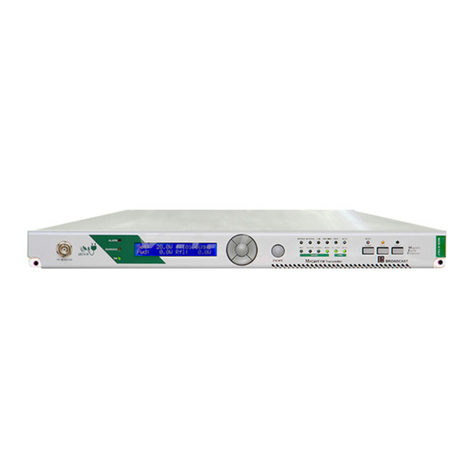
dB PM 1000 User manual

DBELETTRONICA TELECOMUNICAZIONI S.p.A.
PM 1000 – 1 kW FM Broadcasting Transmitter - USER’S MANUAL 1 /101
PM 1000
1 kW FM Broadcasting Transmitter
User’s Manual
Release 1.0.1
- DB ELETTRONICA TELECOMUNICAZIONI S.p.A. -
- Riviera Maestri del Lavoro 20/1 - 35127 Z.I. SUD PADOVA ITALY -- Ph. (049) 870-0588 - Fax. (049) 870-0747 -
- http://www.dbbroadcast.com -

DBELETTRONICA TELECOMUNICAZIONI S.p.A.
PM 1000 – 1 kW FM Broadcasting Transmitter - USER’S MANUAL 2 /101
SAFETY NOTICES
WARNING
To avoid risks of electrical shocks or fire, only qualified personnel should execute the procedures
specified in this manual.
WARNING
When the protective covers of any device or component connected to a 110 / 240 VAC source by a
power cord are removed, voltages and currents dangerous to life may be exposed.
WARNING
Contact with 110 / 240 Volts of alternating current and associated direct current and voltages can be
fatal.
DANGEROUS
RISK OF ELECTRICAL SHOCK DO NOT OPEN COVERS
CAUTION
To reduce the risks of electrical shock, do not remove the cover (or the back). Refer, for servicing,
to qualified service personnel. This installation should be done by a qualified person and should
comply with to all local applicable laws.
NOTICE: ALL THE SPECIFICATIONS AND TECHNICAL INFORMATION IN THIS MANUAL
ARE SUBJECT TO CHANGE WITHOUT NOTICE.

DBELETTRONICA TELECOMUNICAZIONI S.p.A.
PM 1000 – 1 kW FM Broadcasting Transmitter - USER’S MANUAL 3 /101
INDEX
1. PM1000 FM TRANSMITTER................................................................................................................................4
1.1 GENERAL DESCRIPTION ............................................................................................................................... 4
2. TECHNICAL SPECIFICATIONS .......................................................................................................................11
3. INSTALLATION....................................................................................................................................................13
3.1 FREQUENCY CHANGE................................................................................................................................. 14
3.2 ADJUSTMENTS AND MEASURES............................................................................................................... 16
3.3 EXTERNAL CONTROL AND MEASURES .................................................................................................. 17
3.3.1 SYSTEM CHECK SECTION.....................................................................................................................17
3.3.2 MEASURES / CONTROLS SECTION ......................................................................................................18
3.4 GENERAL BLOCK DIAGRAM DESCRIPTION ........................................................................................... 20
4. AMPLIFIER SECTION.........................................................................................................................................21
4.1 GENERAL DESCRIPTION ............................................................................................................................. 21
4.2 30 WPREAMPLIFIER/DRIVER STAGE ....................................................................................................... 21
4.3 AMP30 PRE AMPLIFIER PARTS LIST ......................................................................................................... 24
4.4 AMP300 300 WMODULE AMPLIFIER......................................................................................................... 25
4.5 AMP300 AMPLIFIER PARTS LIST................................................................................................................ 28
5. POWER SUPPLY STAGE....................................................................................................................................32
5.1 GENERAL DESCRIPTION ............................................................................................................................. 32
5.2 POWER SUPPLY BOARD 04011-001 PARTS LIST...................................................................................... 36
5.3 RS-75-24 SWITCHING POWER SUPPLY ..................................................................................................... 39
5.4 0601-008 POWER SUPPLY BOARD .............................................................................................................. 42
5.5 POWER SUPPLY PART LIST......................................................................................................................... 44
6. MODULATOR STAGE.........................................................................................................................................45
6.1 GENERAL DESCRIPTION ............................................................................................................................. 45
6.2 SINTEL ‘96 MODULATOR BOARD.............................................................................................................. 46
6.3 MODULATOR BOARD PARTS LIST............................................................................................................ 53
7. PROTECTION BOARD........................................................................................................................................56
7.1 PROTECTION BOARD N°1 PART LIST ....................................................................................................... 62
7.2 PROTECTION BOARD N°2 PART LIST ....................................................................................................... 70
8. METER STAGE.....................................................................................................................................................71
8.1 GENERAL DESCRIPTION ............................................................................................................................. 71
8.2 METER BOARDS PARTS LIST ..................................................................................................................... 76
9. IN-AUDIO BOARD................................................................................................................................................78
9.1 IN-AUDIO BOARD PARTS LIST................................................................................................................... 80
9.2 IN-AUDIO BOARD JUMPERS SETTING...................................................................................................... 81
10. TRANSMITTER OPTIONS..............................................................................................................................82
10.1 EXTERNAL FREQUENCY CONTROL (/C OPTION)..................................................................................... 82
10.2 EXTERNAL FREQUENCY CONTROL PARTS LIST................................................................................... 84
11. STEREO ENCODER BOARD (/S OPTION)..................................................................................................85
11.1 CHANNELS PRE- EMPHASIS SETTING...................................................................................................... 85
11.2 STEREO ENCODER PARTS LIST ................................................................................................................. 96
12. APPENDIX..........................................................................................................................................................99
12.1 APPENDIX A-XLR AUDIO CONNECTORS PINOUTS.............................................................................. 99
12.2 APPENDIX B-MOSFET REPLACEMENT................................................................................................. 100

DBELETTRONICA TELECOMUNICAZIONI S.p.A.
PM 1000 – 1 kW FM Broadcasting Transmitter - USER’S MANUAL 4 /101
1. PM1000 FM TRANSMITTER
1.1 GENERAL DESCRIPTION
The PM1000 is a complete FM broadcasting transmitter with continuously adjustable output power,
0 to 1050W. Made with MOSFET technology, can be used as stand-alone complete transmitter or
as driver for high power amplifiers.
On the PM1000 the use of MOSFET allows:
- Higher efficiency ( ≈85%);
- High gain (high transconductance and low internal reactive capacitance);
- High thermal stability (negative coefficient for drain current).
The output frequency range is between 87.5 and 108 MHz. Frequency setting is made using internal
dip switches or external selectors (/C option). The minimum frequency step is 10 kHz.
The transmitter has high frequency stability, due to the use of the Digital Phase Locked Loop
system and a very low drift reference quartz.

DBELETTRONICA TELECOMUNICAZIONI S.p.A.
PM 1000 – 1 kW FM Broadcasting Transmitter - USER’S MANUAL 5 /101
An internal deviation limiter controls the maximum frequency deviation, thus avoiding adjacent
channel interference in case of accidental over modulation. In order to limit over modulation, it is
necessary to insert the jumper jp6 in the modulation board to enable the limiter.
Valuable characteristics of PM1000 include intelligent protections. Circuits to protec from load
mismatching (VSWR) and overtemperature (TEMP) allow to otain a very high reliability in all
conditions. Every alarm condition is monitored by means of front panel leds.
The front panel led bar enable the full, easy and fast verification of the main parameters and
condition of operation. The output power, the reflected power, the voltage supply of the power
amplifier, the frequency deviation, L&R audio level, and MPX are continuously monitored.
It is possible, using the front panel adjustments, to control the following settings: output power
(PWR adj.), frequency deviation (DEV adj.), transmitting frequency (option /C), manual/remote
control selection (option /R) and the mono/stereo selection (option /S).
An output 10th order elliptic LP filter ensures a pure RF spectrum, compatible with the most
stringent international requirements. As well, a high efficiency switching mode power supply
reduces the power consumption, and ensures reliable operation.


DBELETTRONICA TELECOMUNICAZIONI S.p.A.
PM 1000 – 1 kW FM Broadcasting Transmitter - USER’S MANUAL 7 /101
Fig. 1.1 - PM1000 TRANSMITTER FRONT VIEW
1) Overtemperature protection indicator 7) Contraves (option /C) 13) Mono/Stereo mode selector 19) L/R channel level measure indicator
2) Indicator of unbalancing between modules 8) RF monitor BNC connector 14) Forward power measure indicator 20) Measure selector
3) Power limiter indicator 9) Output power trimmer adj. 15) Reflected power measure indicator 21) Measure instrument
4) VSWR protection indicator 10) Deviation trimmer adj. 16) Vpa voltage measure indicator
5) Remote shut-down indicator 11) Lock frequency indicator 17) Ipa current measure indicator
6) Indicator of the on/off transmitter state 12) Manual/Remote selector 18) Frequency deviation measure indicator

DBELETTRONICA TELECOMUNICAZIONI S.p.A.
PM 1000 – 1 kW FM Broadcasting Transmitter - USER’S MANUAL 8 /101
Fig. 1.2 – PM1000 TRANSMITTER REAR VIEW
1) RF output DIN 7/16” connector 7) SCA2 input BNC connector 13) MPX input level adj. 19) Sync. input BNC connector
2) Mains power supply connector 8) SCA2 level adj. 14) MPX input BNC connector 20) Interlock BNC connector
3) Mains On/Off switch 9) Left channel (or mono) input level adj. 15) SCA1 level adj.
4) Remote control DB25 connector 10) Left channel (or mono) input XLR connector. 16) SCA1 input BNC connector
5) SCA3 input BNC connector 11) Right channel input level adj. 17) MPX Out BNC connector
6) SCA3 level adj. 12) Right channel input XLR connector 18) AUX input BNC connector

DBELETTRONICA TELECOMUNICAZIONI S.p.A.
PM 1000 – 1 kW FM Broadcasting Transmitter - USER’S MANUAL 9 /101
Fig. 1.3 – PM1000 TRANSMITTER TOP VIEW
1) Blower 6) Remote control board
2) Output filter 7) Protection board (controls)
3) Output coupler 8) Protection board (panel)
4) AMP300, 300 W amplifier boards
5) Switching power supply board

DBELETTRONICA TELECOMUNICAZIONI S.p.A.
PM 1000 – 1 kW FM Broadcasting Transmitter - USER’S MANUAL 10 /101
Fig. 1.4 – PM1000 TRANSMITTER BOTTOM VIEW
1) Sintel ’96 modulator board 5) Power supply board 0601-008
2) Coder stereo board 6) Measure boards
3) Contraves board (/C option) 7) AMP30, 30 W pre-amplifier board
4) Power supply board RS 75-24

DBELETTRONICA TELECOMUNICAZIONI S.p.A.
PM 1000 – 1 kW FM Broadcasting Transmitter - USER’S MANUAL 11 /101
2. TECHNICAL SPECIFICATIONS
RF SPECIFICATIONS
Operating frequency range..........................................................................................87.5 to 108 MHz
Operating frequency setting................................ synthesised with internal dip switches, 10 kHz step
.....................................................................................synthesised by front panel switches (/C option)
Output impedance .......................................................................................................................... 50 Ω
Output connector................................................................................................................................. N
Output power...................................................................................................................... 0 to 1050 W
Power tolerance........................................................................................................................... ±1 dB
Harmonics .................................................................................................................................≤-68 dB
Spurious ....................................................................................................................................≤-80 dB
Syncro AM modulation.............................................................................................................≤-55 dB
Asyncro AM modulation ..........................................................................................................≤-60 dB
Frequency stability
Thermal drift (0 to 50 °C) ....................................................................................................... ±250 Hz
Aging drift..................................................................................................................... ±300 Hz / year
MODULATION
Mono operation
Input level -6 to +10 dBm
Input connector ...............................................................................................................XLR balanced
Input impedance........................................................................................................................... 600 Ω
Bandwidth (± 0.25 dB).................................................................................................20 Hz to 15 kHz
Attenuation of frequencies ≥19 kHz ......................................................................................... ≥50 dB
Preemphasis ..........................................................................................................................50/75 μsec
S/N ratio (± 75 kHz peak dev. with 1 kHz input, 50μs de-emphasised).................................... ≥75 dB
THD+N (± 75 kHz peak dev. with 1 kHz input, unweighted).....................................................≤0.1%
Stereo operation (with stereo coder included in /S model)
L & R input level ............................................................................................................-6 to +10 dBm
Input connectors..............................................................................................................XLR balanced
Input impedance .......................................................................................................................... 600 Ω
Bandwidth (± 0.25 dB).................................................................................................20 Hz to 15 kHz
Attenuation of frequencies ≥19 kHz ......................................................................................... ≥50 dB
Preemphasis ..........................................................................................................................50/75 μsec
S/N ratio (± 75 kHz peak dev. with 1 kHz input, 50μs de-emphasised).................................... ≥70 dB
THD+N (± 75 kHz peak dev. with 1 kHz input, unweighted).....................................................≤0.1%
Stereo separation........................................................................................................................ ≥60 dB

DBELETTRONICA TELECOMUNICAZIONI S.p.A.
PM 1000 – 1 kW FM Broadcasting Transmitter - USER’S MANUAL 12 /101
Stereo operation (with external stereo coder /S option)
MPX input level...............................................................................................2.2 Vpp per 75 kHz dev
Input connector .............................................................................................................................BNC
Input impedance........................................................................................................................... 10 kΩ
Bandwidth (± 0.25 dB)...............................................................................................20 Hz to 100 kHz
MEASURES
Forward power
Reflected power
Vpa units supply
Ipa total of all amplifier units
Deviation
L/R level
PROTECTION
The internal logic circuitry provides proportional feedback protection, without on-air interruptions,
for:
- VSWR
- air over-temperature
- insufficient cooling
- fault of RF stages
AC POWER REQUIREMENTS
Operating voltage............................................................................... 115/230 VAC ± 10 %, 50/60 Hz
Power consumption................................................................................................................. 1760 VA
Battery operation (option /VDC) ....................................................................................48 VDC, 38 A
OPERATING CONDITIONS
Cooling..........................................................................................................forced air by internal fans
Service...................................................................................................................... continuous 24/24h
Temperature range ........................................................................................................... -5°to +45°C
Humidity ................................................................................................................................95% max.
Max. Installation altitude .................................................................................................. 4000 m a.s.l.
WEIGHT AND SIZE
Weight........................................................................................................................................... 48 kg
Dimensions (W x H x D) .....................................................................................483 x 136 x 522 mm
OPTIONS
External frequency setting (/C)
Stereo coder (/S)
Audio processor (/P)
Remote control (/R)
Battery operation (/VDC)

DBELETTRONICA TELECOMUNICAZIONI S.p.A.
PM 1000 – 1 kW FM Broadcasting Transmitter - USER’S MANUAL 13 /101
3. INSTALLATION
To install the PM1000:
1. Connect an antenna or a dummy load to the RF output connector.
2. Verify the correct main supply voltage (230 VAC or 115 VAC).
3. Control that the main ON/OFF switch on the rear panel is in the OFF position (labelled “0”).
4. Connect the transmitter to the main power supply using the power cord included.
5. Switching ON the transmitter: on the front panel (Fig. 1.1) you will see the “MAINS” led ON.
6. Control that the “LOCK” led (Fig. 1.1) on the front panel lights up a few seconds after the power
is turned on.
7. Select the FWD setting, using the Measure select button (Fig. 1.1).
Adjust, looking at the front panel meter, the output power by means of the “PWR” potentiometer
on the front panel (Fig. 1.1).
WARNING: The transmitter can work properly within
±
10 % of the nominal main supply voltage
and is designed to support main supply spikes, although it is preferable to use the main voltage
stabilisers to reduce the risk of damage.

DBELETTRONICA TELECOMUNICAZIONI S.p.A.
PM 1000 – 1 kW FM Broadcasting Transmitter - USER’S MANUAL 14 /101
3.1 FREQUENCY CHANGE
1. Lower the output power to its minimum level.
2. If the exciter is equipped with the “EXTERNAL FREQUENCY SETTING” option (/C) the
selection of the frequency is immediate using the front panel CONTRAVES (Fig. 1.1).
The weights of the contraves numbers are as follows;
3. If the transmitter has internal frequency setting, to change frequency open the cover of the Sintel
’96 modulator board (see Fig. 1.4) and use the internal dip-switches. The weight of the internal dip-
switches is indicated on the next page. To find the correct dip-switches configuration corresponding
to the needed FM channel, please refer to the following example with 98 MHz frequency.
4 - Put every dip-switches in the ON position.
5 - Select the OFF position for the dip-switch with the maximum weight, lower than or equal to the
frequency wanted (for example f0= 98 MHz put on OFF the 81.92 MHz switch).
6 - Select 98 - 81.92=16.08 MHz, the minimum weight, lower than or equal to 16.08 MHz, is 10.24
MHz; now put off the corresponding switch.
7 - Select 16.08 - 10.24 = 5.84 MHz, the minimum weight, lower than or equal to 5.84 MHz, is 5.12
MHz, now put off the corresponding switch.
8 - Select 5.84 - 5.12 = 0.72 MHz, the minimum weight, lower than or equal to 0.72 MHz, is 0.64
MHz, then put off the corresponding switch.

DBELETTRONICA TELECOMUNICAZIONI S.p.A.
PM 1000 – 1 kW FM Broadcasting Transmitter - USER’S MANUAL 15 /101
9 - Select 0.72 - 0.64 = 0.08 MHz, there is a weight equal to 0.08 MHz, so put in OFF position the
corresponding switch to complete the setting.
The final configuration is:
10 - Adjust the desired output power using the “PWR” front panel potentiometer.

DBELETTRONICA TELECOMUNICAZIONI S.p.A.
PM 1000 – 1 kW FM Broadcasting Transmitter - USER’S MANUAL 16 /101
3.2 ADJUSTMENTS AND MEASURES
AF INPUTS DEVIATION ADJUSTMENT
For the Left and Right input signals (/S option) use the corresponding XLR female connectors on
the rear panel. The input impedance is 600 Ω.
The transmitter accepts, adjusting input trimmers, input signal levels from -6 dBm to +10 dBm for a
75 kHz peak deviation.
For Mono input signal (PM1000 without inner stereo generator) the input female XLR connector
have the same input levels than the stereo amplifier.
For MPX input signal (PM1000 without inner stereo generator) the BNC input connector, labelled
MPX (10 kΩinput impedance), accepts a 0 dBm for 75 kHz peak deviation input level.
For SCA signals (>53 kHz) use BNC input connectors (1 kΩinput impedance) (Fig. 1.2): the input
level for a correct deviation of the main carrier (≈1.25 kHz peak) is 2.2 Vpp. To adjust the peak
deviation of the main carrier use the “DEV” front panel potentiometer (Fig. 1.1): look at the front
panel meter and select the DEV measurement by means of the selection button “READINGS
SELECTOR” (Fig. 1.1).

DBELETTRONICA TELECOMUNICAZIONI S.p.A.
PM 1000 – 1 kW FM Broadcasting Transmitter - USER’S MANUAL 17 /101
3.3 EXTERNAL CONTROL AND MEASURES
3.3.1 SYSTEM CHECK SECTION
See Fig. 1.1
On the front panel there is a section labelled “SYSTEM CHECK” which allows monitoring of all
the main functions and protections of the transmitter.
⇒“ON” led: It shows the on/off state of the transmitter, thus the presence of a main power supply.
⇒“OVERHEAT” led:It indicates that the overtemperature protection is on. This protection does
not need a RESET because it restores the normal working conditions automatically when the
temperature goes back to normal values.
⇒“VSWR” led: It shows that the VSWR protection is active. This intelligent protection is
characterised by an automatic reset delayed by about 2-3 seconds to avoid the risk of accidental
intervention. This autoreset tries to resume to normal operation only 3-4 times, then turns off the
transmitter definitively.
⇒“REMOTE SHUT-DOWN” led: It is enable if the amplifier has the /R option.
When it is light on, shown that power output has zero worth because of a remote external
impulse.
⇒“UNBAL” led: It shows the unbalancing between the two AMP300 amplifier modules, thus an
equipment malfunction.

DBELETTRONICA TELECOMUNICAZIONI S.p.A.
PM 1000 – 1 kW FM Broadcasting Transmitter - USER’S MANUAL 18 /101
3.3.2 MEASURES / CONTROLS SECTION
On the front panel (Fig. 1.1) there is a 40 leds meter bar (see Fig. 1.1) which displays the most
important parameters of the transmitter. The push-button labelled “MEASURE SELECT” selects
the measure type, as indicated by one of the leds below the bar.
You can visualise 6 parameters:
-FWD measure displays the output power (f.s. 1200W).
-REFL measure displays the reflected power (f.s. 120W).
-Vpa measure displays the bias of final transistors (f.s. 60V).
-Ipa measure displays the absorbed current of final transistors (f.s. 60A).
-DEV measure displays the peak deviation of modulated carrier (f.s. 200KHz).
-L/R measure displays the input audio level. (the meter bar is split in two parts, one for each
audio channel).
⇒“LOCK” led: shows the correct lock of the frequency synthesis circuit (PLL) on the modulator
board.
⇒“STEREO” led: shows the use of the internal stereo generator board (if present). This led is
related to the switch (Fig. 1.1) labelled “STEREO/MONO” which allows selection of the type of
signal to be modulated. The mono signal is obtained by a semi-sum of the left and the right
signals for the PM1000. If the internal stereo generator board is not present, the switch
mentioned above and the corresponding LED are unused.
⇒“REMOTE” led: indicates if the operation of the transmitter can be remote controlled. This
selection is made using the switch “ REMOTE/MANUAL”. This switch and the relative led will
be unused if the transmitter is not equipped with the remote control board option.

DBELETTRONICA TELECOMUNICAZIONI S.p.A.
PM 1000 – 1 kW FM Broadcasting Transmitter - USER’S MANUAL 19 /101
Fig.3.1 – PM1000 GENERAL BLOCK DIAGRAM

DBELETTRONICA TELECOMUNICAZIONI S.p.A.
PM 1000 – 1 kW FM Broadcasting Transmitter - USER’S MANUAL 20 /101
3.4 GENERAL BLOCK DIAGRAM DESCRIPTION
The general block diagram (see Fig.3.1) consists of the following blocks:
A) PM1000 RF Amplifier Stage delivers the 1050W output power.
It is realised by means of the following modules:
1) AMP30 (DB 0110_010A) preamplifiers/driver stage for delivering about 24 W RF power.
2) Input splitter (DB 9701_001+DB 9702_007) that divide the 24 W in four equal parts to driving
the four AMP300 final amplifiers.
3) Four AMP300 300 W MOSFET technology amplifiers (DB 9812_001).
4) Output coupler (DB 9702_008+9701_002A) for combining the four 300W stage outputs and to
obtain the full output power.
5) Output low-pass filter (DB 9901_001) and directional coupler (DB 9901_005) for
spurious and harmonic filtering and for forward and reflected output power monitoring.
B) Protection and control board (DB 9601-002) for monitoring and controlling all principal
transmitter parameters.
C) PM 1000 Power Supply Stage. For driving the RF section there is a mains switching board,
giving the correct power supply (45V) for each 300W RF amplifiers. An other switching module
(DB 0206_090) is dedicated for protection and control board, meter stage, Modulator board,
AMP30 Driver stage and all optional boards.
D) PM1000 Meter stage display on a 40 LED scale all major transmitter parameters.
E) SINTEL 96 modulation board allows a high quality direct carrier modulation accepting a
composite stereo (MPX) coming from Stereo encoder (/S option) or a mono input signal with up to
3 SCA subcarriers (for example RDS, ARI, ...).
F) Stereo encoder board (/S option) generates a composite MPX signal for the modulation board
from R and L audio channel.
G) Stereo audio processor (/P option) performs a high quality sound compression.
H) Remote control board (DB 9702-006).
Table of contents
Other dB Transmitter manuals
