dbx 160X User manual

dbx1sox
PROFESSIONALSINGLE-CHANNEL
COMPRESSOR/LIMITER
INSTRUCTIONMANUAL
Used with the permission of AKG ACOUSTICS, INC.

1,0 INTRODUCTION
1.1 PRODUCT DESCRIPTION
The dbx Model 160X is a professional single
channel compressor/limiter that features an
exclusive combination of the dbx Over Easy
and ''hard knee'' compression characteristics. dbx
. Over Easy compression permits extremely smooth,
almost inaudible transitions into compression due
to the gradual change of compression ratio around
the threshold. The 160X offers the user the choice
of using the Over Easy curve or a mathematically
precise "hard" threshold-at any compression ratio
selected . The 0'!er Easy curve, coupled with dbx's
true-RMS level detector, wide-range Blackmer
voltage-controlled amplifier (VCA) and feed-
forward circuitry, makes it possible to achieve
large amounts of compression without adverse
audible side effects. These features also allow the
160X to actually be set for INFINITY+™
compression . This is a special negative compression
effect whereby the program dynamics are
inverted above the set threshold (i.e., the higher
the input level, the lower the output level).
The detectors of two Model 160X's can be
coupled so that stereo programs are compressed
with stable imaging, by means of a simple patch
cable between the two units . The stereo coupling
can be disengagedinstantly by a front panel
pushbutton .
Program-dependent attack and release times
assurenatural sound without the need for con-
tinuous manual adjustmenu. Threshold and
compression ratios are adjustable over a wide
range, so virtually any line level signal can be
processed effectively. Output gain is also adjustable
over a very wide range (±20 dB). These features
make the Model 160X compatible with the
operating levels of virtually all professional sound
and creat ive audio equipment.
For metering , the 1GOXprovides a true AMS
dua l wide-range LED array which simultaneously
shows the an1ount of gain reduct ion up to 40 dB•
and the input or output level from -40 dB to
+20 dB, depending on the setting of a front
panel switch .
The 160X also features a true ''hard-wi red by -
pass" switch , separatedetector inputs , Tip/Aing/
Slec:vcphone jacks as .well as barrier strip con-
nectors, balanced active inputs and +24 dBm
single-ended output drive capability which can be
field-modified to provide transformer or active
bal;inced operation .
The dbx Model 160X is well suited to a broad
ranf)c of applications including tape recording ,
disc master ing, radio and TV production and
bro;idcast , live concert sound reinforcement,
mobile and theatrical production .
•Th~ Ir.nx is c11p•bl~ of gr••t~ r th•n 60 dB of comp,.u ion.
IMPORTANT FOR UK USERS
Thewiresin this mainsleadarecolored in
accordancewiththe following code:
Blue:Neutral
Brown:Live
Asthe colon of the wir• in the mainsleadof
this .epparatusmay not correspond with the
colored markings identifyingthe terminals in
your plug, proceed as follows:
The wirethat is colored blue must be
connected to the terminal that is marked
with the letter N or colored black;
The wire that is colored brown must be
connected to the terminal that is marked
with the letter L or colored red.
Ensure that all terminals are securely
tightened and that there art no .loose strands
of wire.
WARNING
This unit must be protected by a 3-amp fuse,
preferably using a fused plug. Also, do not
remove the cover without first disconnecting
the unit from the mains supply.

1.2 160X FRONT PANEL
dbx • • ....................._
-----············--·
............ ---
1B0X t S I
---
• C D E F Q H I
Fif. 1·1 - Model 110X Fro,,t Panel
A. BYPASSSWITCHANO INDICATOR
Depressingthe BYPASS button creates a
"hard-wire bypass" of the 160X's circuitry by
connecting the input directly to the output; the
LED above the switch turns ON in Bypass mode.
B. SLAVE SWITCH ANO INDICATOR
Depressingthe SLAVE button on one 160X
of a stereo pair determines that the other 160X
will be the Master (the controlling unit). The LED
above the SLAVE button turns ON when the
160X is in SLAVE mode, indicating that the front
panel functions (with the exception of BYPASS
and DISPLAYselect switches) are deactivated and
under control of the Master 160X. When neither
160X is in SLAVE mode, each will operate
normally asa mono compressor/limiter.
C. THRESHOLD CONTROL
Adjusting this knob sets the threshold of
compression from -40 dBm (7.8mV) to 20 dBm
(7.8 V). In hard-knee compression mode, the thres•
hold isdefined as that point abovewhich the out•
put levelno longer changes on a 1:1 basiswith
changes in the input level. In Over Easy mode, the
threshold of compression is defined as the
approximate middle of the Over Easy threshold
region, as shown in Figure 3-1.
2
0. OVER EASY SWITCH
Depres.sing this button changes the threshold
mode to dbx's Over Easy characteristic. and allows
the middle (an1ber)T~~RESl-iOLOLED to turn ON
w:1P.11 thP.signal is in the Over Easy region. When
this button is out , the 160X oµerates as a hard-
k1ice c:on1pressor/Iimiter.
E. THRESHOLD INDICATORS
These three LEDs indicate the relationship
of the input signal level to the threshold of com-
prc~sion. The green "BE LOW" LED is ON when
the signal is below threshold and the red "ABOVE"
l[ D is ON when the signal is above threshold.
When the 160X is switched to Over Easy mode,
the amber LED is ON when the signal is in the
Over Easy region (Refer to Figure 3-1).
F. COMPRESSION RATIO CONTROL
Rotating this control in a clockwise direction
increases the maximum amount of compression
from 1:1 (no compression) up to infinity :1 (no
increase in RMS output regardless of input level
increasesabovethreshold); further clockwise
rotation increases compression into the
INFINITY+ region, up to• maximum of-1:1
(i.e., 1 1 dBd«reast1in input levelcauses a 1 dB
increasein output level). In the INFINITY+ region,
the 160X inverts the program dynamics for
special effects.
G. OUTPUT GAIN CONTROL
Adjusting this control varies the amount of
fixed gain (up to ±20 dB) in the 160X's output
amplifier stage. The OUTPUT GAiN control does
not interact with the threshold of compression.
H. DISPLAY FUNCTION SWITCHAND
INDICATORS ·
Depressing this button causes the upper
LEO arrayto displaythe INPUT level to the 160X.
With the button out, the OUTPUT signal level is
displayed. A pair of LEDs immediately above the
OISPLAY switch indicates the selected display
•
status.
I. LEVEL ANO GAIN REDUCTION
DISPLAYS
The upper row of 19 LEDs displays either
the INPUT or OUTPUT level, as selected with the
DISPLAY switch. This display is factory set so that
0 dB is equivalent to +4 dBm input or output levf:I
(1.23 V rms), but may be reset with the rear panel
METER CALIBRATION trimmer. (SeeSection 3.5
for recalibration instructions.)
The lower row of 12 LEDs displays up to
40 dB of GAIN REDUCTION being caused by the
160X. (Fixed gain changes commanded by the
OUTPUT GAiN control are not displayed by the
gain change LEDs but are reflected in the output
leveldisplay.)

1.4 SPECIFICATIONS
Input Impedance
Input Level
Output Impedance
Output Level
Threshold Range
CompressionRatio
MaximumCompression
Thre1holdQ'laracteristic
Attack Timen>
ReleaseTime
Output Gain
SlewRate
DynamicRange<
2 1
Equivalent Input Noise (unweighted)
Frequency ResponM
Distortion BelowThreshold<>>
Distortion AboveThreshold <
4 >
Metering
Meter Zero Set
Indicators
Controls andSwitches
Connectors
Dimensions
Wei~t
Power Requirements
Acc!!ssories
Signalinput: 60 kO, unbalanced; 100 kO, bllanced.
Detector input: 230 kn, unbllanced; 460 kn, balanced.
+24 dBm maximum.
22 n,designedto drive8000 or greater.•
+24 dBm into 600 norgreatar.
Variablefrom -40 to +20 dBm (7.8 mV to 7.8 V RMS).
OverE•y: Program-dependent.afflCtld by THRESHOLD,COMPRESSION
RATIOsettings(COMPRESSIONRATIOcontrol determinesmaximum
compression ratio), continuously variablefrom 1:1 to •:1 to -1 :1.
Hard•knee:COMPRESSIONRATIOMttlngdefinesexact compression ratio.
continuously variablefrom 1:1 to•:1 to-1:1.
>60dB
OverEasyor hard•knN (switchAlectablet.
Program-dependent: 15 ms for 10 dBincreae in Input level (above
threshold), 5 ms for 20 dB, 3 ms for 30 dB.
Program-dependent;variesautomatically from 0-600ms,affected by
settings of front panel controls.
Variablefrom -20 to +20 dB.
>10 V/us
>113 dB
<-89 dBm, 20 Hz- 20 kHL
+<>,-1dB, 20 Hz- 20 kHz.
2nd harmonic 0.07%;3rd harmonic 0.07".
2nd harmonic 0.07%;3rd harmonic o.oa.
19 LEO INPUTor OUTPUTdisplay from -40 to +20 dB, 12 LEOGAIN
REDUCTIONdisplay from -1 to -40 dB.
-15dBm to +10 dBm.
BELOW/threshold/ABOVE(grNn, yellow, red),INPUT (red), OUTPUT (red),
SLAVE (yellow), BYPASS(red).
THRESHOLD,COMPRESSIONRATIO, OUTPUTGAIN, DISPLAYfunction
switch, meter zero adjust, BYPASSswitch, SLAVEswitch, OVER EASY
switch.
lnput/outpUt: TRS phone jacksand blrrier terminal.
Detector: barrier terminal
Strapping: TRS phone jack
1·3/4" H x 19" W x 9-1/4" 0 (4.4 cm x 48.3 cm x 18.4 cm).
6.5 lbs (3.0 kg)
115/220 VAC :t:10%,50-60 Hz, 8 W
AB·1 active balanced output card.
'
(I) Measured in the infinite compres1ion ,~ion of tht thrt1hold curve, tim. required to reduce 1i11nelby 63~ of ltvtl incrtaM (above threshohJl.
'
12) Defined•• tht difference bet-n the maxin1um 1i11nallevel end the "A" weighted noiM floor•• mea,ured at the output.
(l I l'.1111uredet 1 kHz, 0 dBm input and output .
1•1 F,gures are typical at infinite comprnsio11. 1 kHz, 0 dBm input and output - 2nd harmonic is relatively unaffected by compression ratiti ,
time constant, end freQuency, while 3rd harmonic decretMI with llower time con1111nta,higher frequencies ind lower compression rauos .
0Tran1fo,,,,., for i1ol•r«I floating output •11•ilabl• dirat:tly from:
Jl!111t!nTr•n1form,r,, 10135 Burbank 8l11d.,North Hollywood, CA 91601. (SH s«tion 2.3.4.J

3.0 OPERATION
3.1 OUTPUT CONTROL
This control sets the amount of fixed gain in
the 160X's output stage over a range of ±20 dB.
Fixed gain added or subtracted by the OUTPUT
control from signal passing through the 160X
is not affected by the setting of the THRESHOLD
control. Gain changes brought about when the
input signal exceeds the THRESHOLD reference
sett ing·are in addition to those ·caused by the
OUTPUT control.
,3.2 THRESHOLD CONTROL
In hard-knee mode this control sets a reference
level above which input signals will be processed
by the 160X's gain change circuitry in the manner
defined by the setting of the RATIO control.
Input signals which fall below this level will pass
through the 160X unprocessed (except for fixed
gain changes directed by the OUTPUT control) .
In Over Easy mode, signals begin to gradually
activate the 160X's gain change circuitry as they
approachthe THRESHOLD reference level and
they do not get fully processed in the manner
defined by the RATIO control until they have
passed somewhat above the THRESHOLD
• 20
.·~
- • I(\ }
r!t
~
1
..., '
~
1;: I
..,
. J • " • · I -
-
-Rro
-
(\ .
. ..
-' •
0 I
• I(1
~
I .....
,.,_,....
•:t
~
__ ,._<, Oe!o.. """_''...'°'_'_' ____ .__.
• 20
• 15
• 1!> - IC • 5 (J • 5 • 10 • I!, • 20
INl"\IT I.( 1/[ L 11181
- • ,c
QI /.
~
,.1
-RED
_, • 5
w Abowc 1h,.-d,,Jld
'.• 20:1
...
.., 0
..
::, •:1
~
. 5
..
::, Rot•IIOII Po,nl Th,tshold
0 10
- 15 Btlow thttshold
- 15 - 10 - 5 0 • 5 • 10 • 15 • 20
INPUl LEVEL td81
Fig. 3-1 - Over Env va. Hard•K"" Compreaion
reference level. In Over Easymode there is no
distinct point at which processing begins, and the
THRESHOLD setting corresponds to a point on
the input/output transfer curve midway between
the onset of processing and that point at which
the transfer curve corresponds to the setting of
the RATIO control (Figure~1).
NOTE: The THRESHOLD setting relates to the
signal level seenby the DETECTOR input. In
normal operation. the program signal input is
connected directly to the detector input. If this
is not the case, the signal actually present at the
detector input will determine whether and how
the 160X processes the signal coming into its
SIGNAL INPUT.
. .
3.3, RATIO ,C.ONTROL
When an input signal is above the THRESHOLD
reference level, the setting of this control determines
the number of dB by which the input signal must
change in level to produce a 1 dB increase in the
signal level at the output of the 160X. A setting
of 2: 1 indicates an input:output ratio where in a
2 dB increase in input signal (above threshold) will
produce a 1 dB increase in output signal. A setting
of oo:1 indicates that an infinite increase in input
level would be required to raisethe output level
by 1 dB. . .
The 160X's RATIO control covers the entire
range from 1:1 to oo:1 and, in addition, goes to
Infinity+ (negative) ratios. At a setting of -1 :1,
the above threshold input signal must decrease
hy 1 dB in level to increasethe signal at the
output of the 160X by 1 dB.
The control curve of the RATIO potentiometer
has been designed to provide total operator
control, with scale expansion at the subtle lower
ratios for easy, repeatable settings.
• 20
• 15
ci• 10
'0
-
...
• 5
...
>
... 0
...
..
:,
~
-5
..
:,
0 - 10
• 15
. , 1 e,1
\ / 101 Fig. 3·28 - Ratio Con1,01
~.1, ,
•.,- I
x,1
-a,,
,,, -1,1
COMl9A •aa10N
RATIO
\h,tshold
_,
-1 :1
- 15 - 10 - 5 0 • 5 • 10 • 15 • 20
INPUT LEVEL tOBI
Fit- 3-2A - Typical Trllltfer Cwrv•
Fis- 3-2 - Ratio
11

3.4 STEREO STRAPPING
Two channels of program material do not
necessarily constitute a stereo program. A stereo
program is one where the two channels are
recorded and/or mixed to create the illusion
of a sir)gle,unified "panorama" of sound. The
stability of the psychoacoustic "image'' of each
sound source within the stereo program depends
upon·its ability to maintain a specific phase and
amplitude relationship from left to right channel.
If two independent compressors are used to
process the stereo program, a loud sound occurring
in one channel will cause a gain reduction only in
that channel. This gain reduction would cause the
perceived image of any sound spread between the
two channels to move toward the side which had
not been compressed, because the spreadsignal
would be momentarily softer in the compressed
channel. This can be avoided by linking the two
compressors in such a way that both channels
receive the same amount of compression - an
amount equal to the maximum ''needed''by
either channel at that moment. On the 160X,
this is accomplished by means of the
STRAPPING jacks; a cable between these
jacks permits the RMSdetectors of both -units
to "talk" to one another - but only when one
of the units' SLAVE buttons is depressed.Each
compressor then senses the incoming signal
level, which is compared to the threshold set on
the master (the unit whose SLAVE button is
not depressed). If the comprealon Is;equiredby
either channel, both channels are a,bject to
compression - the same amount of it - so the
stereo image remains stable.
When compressing astereoprogram with a pair
of 160Xs, only the master unit controls need be
adjusted.
12
3.5 METER CALIBRATION
The INPUT/OUTPUT LEVEL DISPLAY in thr
160X is factory.calibrated to indicate "O" when
the signal level is +4 dBm (1.23 V) at either the
input or output of the 180X, depending on the
DISPLAY function switch position. (The
METER CALIBRATION control does not affect
the-GAIN CHANGE LEDs.) ·.
To recalibratethe LEVEL DISPLAY, depress
the DISPLAY button to meter the INPUT LEVEL,
andfeed a 1 kHz signalat the selectednominal
operating level (the level desired for a''O dB"
meter indication) to the 180X's SIGNAL INPUT.
Then adjust the rear panel METER CALIBRA-
TION control until the meter indicates ''O dB."

4.0 TYPICAL APPLICATIONS
4.1 SMOOTHING VARIATIONS IN VOCAL
LEVEL
When the distance between a vocalist and a
microphone changes, variations in signal level occur.
Start with the 160X adjusted for low compression
(around 2:1) and adjust the THRESHOLD control
for optimum results,then increaseRATIO if
necessary.
. .
4.2 SMOOTHING VARIATIONS IN
INSTRUMENT LEVEL
To achievea smootherelectric-basssound,
compress the instrument's output with a ratio of
about 4: 1. Compression lessens the loudness
variations among the strings and increases the
sustain. Other instruments, such as horns, vary in
loudness depending on the note being played,and
benefit similarly.
NOTE: When compressing a stereo program with a
pair of 160Xs, the factors affecting a compression
curve, and the actual compression and threshold
settings, are like those previously covered with
reference to single channels of program material.
However, it will generally be found that large
amounts of compression are more audible in a
mixed stereo program than they might be on the
separate tracks that were mixed to create the
program.
4.3 RAISING A SIGNAL OUT OF A MIX
Since reducing dynamic range increases the
averagesignal leveland meter readings by a small
amount, a single track can beraised out of a mix
by boosting its level slightly and applying com-
pression. It isalso possible to separate certain
vocals or instruments from a mono program
already mixedby following the procedurein
Section 4.6.1.
4.4 PREVENTING TAPE SATURATION
With programs of widely varying levels,com•
pression can prevent recording levels from satur•
ating tape tracks (see also Section 4.7.1).
4.5 SPEAKER PROTECTION
Compressors are frequently used to prevent
excessiveprogram levels from damaging drivers in
a sound-reinforcement system. Limiting also
benefits intelligibility by allowing low-level input
signalsto be reproduced through·the system at
higher volume. In a musical performance, this
provides additional intimacy as the vocalist's
whispers are heard clearly at each seat in the house.
The Over Easy curve utilized by the 160X permits
a very high amount of compression (10:1 or
greater) to be used in many situations. Vocalists
and musicians don't get the sense of being "choked
back", but high average levels can bemaintained
without the speaker damage which would
norn,ally occur due to excessive heat buildup
in the drivers.
In circumstances wherethe 160X isexpected
to causenochangein gain unless an emergency
arises (wildly excessive levels) some operators
set the RATIO to•: 1, the THRESHOLD to the
highest permissible level, and operate the unit in
hard-knee mode. (In hard-knee mode, the 160X
will perform in the mannerof Itspredecessor, the
16Q.)Asageneralrule,the comprnaors should be
asclou to th11•mplifi11r, • p0$$ibl• in the signal
chain. If the 180X Isplaced before the EQ, for
example, 1 potentially damagingboost in EQ
won't bGseen by the unit and the speakers may
be damaged. (See Section 4.8.2.) For maximum
sound-pressure levels, largesound-reinforcement
systems frequently useaseparatecompressor on
each output of the electronic crossover(s). For a
stereo sounckeinforcement system, stereo
strapping cabin should be run between the 160Xs
in each band (low-low,.mid-mid,.etc) •
•
4.8 INFINITY+T~ COMPRESSION
.
It has been noted that with a full-scale
Infinity+ setting of-1.1, a 1 dB decreasa
of input level above THRESHOLD causes a
1 dBincmnt1of output level. It can be seen
how this differs from the full counter-
clockwise setting of 1:1, where the transfer
function is linear (e.g., a 1 dB increas11of input
levelcauses a 1 dB decreaseof output level).
A total dynamic reversal of the entire program
being processed will not occur unless the
THRESHOLD isset very low (e.g., -40 dBm)
and all the program material falls above the
threshold level. More often, some of the
program input will be below threshold, and
will therefore have normal dynamics - that
is, the output level will change linearly with
changes of input level. As the input level rises
above threshold, however, the output level will
begin to decrease. The audible results will differ
with different types of program material and
different settings. With instruments havina_fast
attack times, such asapicked guitar, a harpsichord,
or a drum, a low threshold will all but eliminate
the attack transient. Interesting effects can be
obtained by setting a moderate threshold with
instruments with a slower attack, such as wind
instruments or bowed strings; the level will build
normally up to the threshold, then begin going
lower, the output will become very quiet as the
instrument is generating its loudest sound, perhaps
quieter than when the note first began.
4.7 USING THE DETECTOR INPUT
4.7.1 Detector EQ For Signal Enchancement
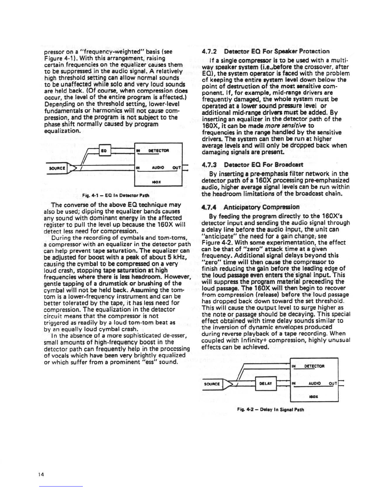
It is possible to separate certain vocals and
instruments from a mix by frequency-weighted
compression. With an equalizer ioserted ahead of
the detector input (but not in the audio path), the
equalization settings do not shift the timbre or
frequency response of the audio signal. They
merely alter the threshold response of the com-
13

pressor on a "frequency-weighted" basis (see
Figure 4-1). With this arrangement, raising
certain frequencies on the equalizer causes them
to be suppressed in the audio signal. A relatively
high threshold setting can allow normal sounds
t~ be una~fected while solo and very loud sounds
are held back. (Of course, when compression does
occur, the level of the entire program is affected.)
Depen.ding on the threshold setting, lower-level
fundamentals or harmonics will not cause com-
pression, and the program is not subject to the
phase shift normally caused by program
equalization. ·
10 ..NffCTOR
IOUflCI ., .. AUDIO OUT-
-
leOJI
Fig. 4•1 -EQ In DetKtor Padl
The converse of the aboveEQ technique may
also be used; dipping the equalizer bands causes
any sound with dominant energy in the affected
register to pull the level up because the 160X will
detect less need for compression.
During the recording of cymbals and tom-toms,
a compressor with an equalizer in the detector path
can help prevent tape saturation. The equalizer can
be adjusted for boost with a peakof about 5 kHz.
causing the cymbal to be compressed on a very
loud crash, stopping tape saturation at high
frequencies where there is less headroom. However,
gentle tapping of a drumstick or brushing of the
cymbal will not be held back.Assumingthe tom-
tom is a lower-frequency instrument and can be
better tolerated by the tape, it has less need for
compression. The equalization in the detector
circuit means that the compressor is not
triggered as readily by a loud tom-tom beat as
by an equally loud cymbal crash.
14
In the absence of a more sophisticated de-esser,
small amounts of high-frequency boost in the
detector path can frequently help in the processing
of vocals which have beenverybrightly equaHzed
or which suffer from a prominent "ess"sound.
.
4.7.2 Detector EQ For SpeakerProtection
If a single compressor is to beused with a multi-
way speaker system (i.e.,before the crossover, after
EQ), the system operator is faced with the problem
of keeping the entire system level down below the
point of destruction of the most sensitive com-
ponent. If. for example, mid-range drivers are
frequently damaged, the whole system must be
operated at a lower sound pressure level or
additional mid-range driven must beadded. By
inserting an equalizer in the detector path of the
160X, it can be made more unsitive to
frequencies in the range handled by the sensitive
drivers. The system can then be run at higher
averagelevels and will only be dropped back when
damaging signals are present.
4.7.3 DetectorEQForBroadcast
By inserting a pre-emphasis filter network in the
detector path of a 160X processing pre-emphasized
audio, higher averagesignal levels can be run within
the headroom limitations of the broadcast chain.
4.7.4 AnticipatoryCompression
By feeding the program directly to the 160X's
detector input and sending the audio signal through
a delay line before the audio input, the unit can
"anticipate" the need for a gain change; see
Figure 4-2. With some experimentation, the effect
can be that of "zero"attack time at a given
frequency. Additional signal delays beyond this
''zero" time will then cause the compressor to
finish reducing the gain before the leading edge of
the loud passageevenentersthe .signal input. This
will suppress the program material preceeding the
loud passage.The 160X will then begin to recover
from compression (release)before the loud passage
has dropped back down toward the set threshold.
This will cause the output level to surge higher as
the note or passage should be decaying. This special
effect obtained with time delay sounds similar to
the inversion of dynamic envelopes produced
during reverse playback of a tape recording. When
coupled with Infinity+ compression, highly unusual
effects can be achieved.
IN OfTECTOft
j ....
IOUIICE ......_ I DILAY IN AUDIO OUT
....
leOJI
Fit- 4-2 -Deley In Sitnal Path
Other manuals for 160X
2
Table of contents
Other dbx Air Compressor manuals
Popular Air Compressor manuals by other brands

Schneider Airsystems
Schneider Airsystems UNM 210-8-25 W operating manual

Ingersoll-Rand
Ingersoll-Rand GHH RAND SILU CS1050 LITE operating manual

Powerex
Powerex SE Series operating & maintenance manual

anko
anko 43058150 user manual

SGS
SGS SC100V owner's manual

F.F. Group
F.F. Group AC-B 90/4MC PRO Original instructions