DC Power Solutions B-COOL9000RM-12V User manual


INDEX:
Introduction & Company information...............................................................4
Safety instructions.............................................................................................. 5
Parts List .............................................................................................................. 6
B-COOL 9000 Specifications ............................................................................. 7
Parts List .............................................................................................................. 8
Installation............................................................................................................ 9
Technical & Install Specifications............................................................... ...10
Fault analysis.................................................................................................... 11
Operating Instructions......................................................................................12
Compressor / Trouble shooting ......................................................................13
Air Conditioner /Trouble shooting..................................................................14
Refrigerant Leakage..........................................................................................15
Maintenance.......................................................................................................16
SALES
OFFICE: 604-599-9200
MOBILE: 778-233-3905
For Sales Information:
Introduction
B-C OOL9000 is a fully self-contained –one piece - roof mount AC unit, available in 12 and 24 volts with
an inside cab air diffuser, ready to connect wire harness / battery cable and fuse block and comes pre-
charged with R134a refrigerant.
In other words –our roof mount air conditioner comes ready to go.
DC Power Solutions provides this document for informational purposes only. DC Power Solutions has
devoted significant time and effort to compile manuals (Installation, Maintenance and Trouble-shooting) to
assist customers with the installation of the AC and product usage. However, DC Power Solutions makes
no representations warranties expressed or implied with respect to the information, recommendation s
and descriptions contained within this and other documents. Information from the manuals should at no
time be regarded as covering all contingencies. If you are in need of additional information, contact DC
Power Solutions directly.
DC Power Solution’s warranty shall not apply to any product which has been installed, maintained,
repaired or altered in a manner as to affect the product’s integrity. Any alteration of these products and
deviation from suggested installation process without written approval will void DC Power solution’s
warranty.
DC Power Solutions accepts no liability to any person or entity for personal injury of any kind, property
damage, or any other direct, indirect, special, or consequential damages whatsoever arising out of the
use of the manuals or deriving from any information, recommendations or descriptions contained in the
manuals.
To ensure the durability of DC Power Solutions products, please follow and understand the instructions
within the manuals.
Recycle and dispose of the air conditioning unit properly to help keep the environment healthy.
There are Federal, Provincial and State regulations regarding the disposal of refrigeration /AC machines.
Consult a professional and ensure they follow the laws when disposing of the refrigeration/AC unit.
4

Recommendations / Safety instructions
The installation must be performed by a qualified
professional.
Switch off / disconnect the battery before installation
and performing maintenance work.
Wear goggles and gloves for the installation of this
product or disassembly an item for repair.
ATTENTION: The unit must be cooled before any work
is performed. Some parts are hot and can cause burns.
ATTENTION. Do not remove any protection provided
on the unit. This could cause serious injury.
ATTENTION: The unit is heavy. Do not handle or
install the unit alone.
5
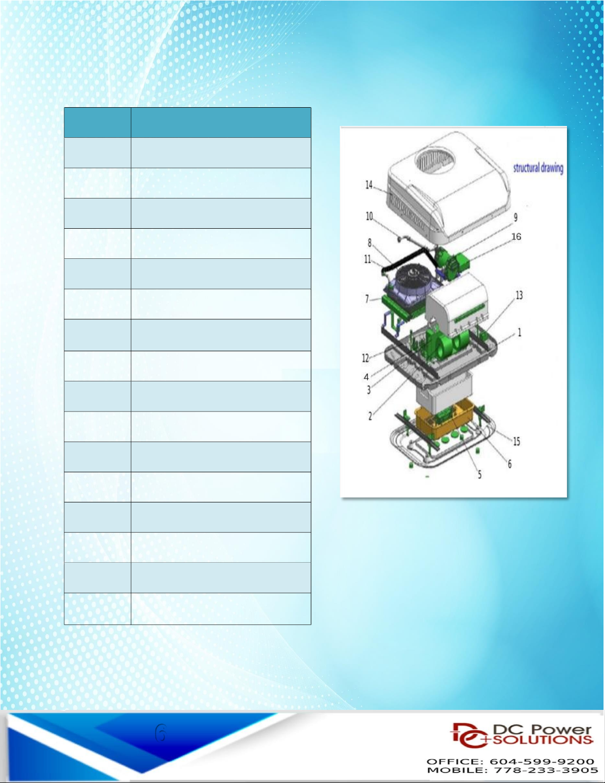
Parts List
6d
Item PART LIST
1 ase frame
2 lower motor
3 External Motor assembly
4 Expansion valve
5 Evaporator
6 Internal cover
7 Condenser
8 Condenser fan 12V/24V
9 Compressor 12V/24V
10 Piping
11 Hose
12 Dryer
13 Thermostat
14 Top cover
15 Decorative Cover
16 Compressor Controller
6

-Cool 9000 - Fully Self-Contained - 100% Electric
MODEL # -COOL9000RM12V -COOL9000RM24V
Voltage 12V 24V
Compressor type 25cc Electric scroll
compressor
25cc Electric scroll
compressor
Max. current 70amps 40 amps
Working current 50-70 amps 15-40 amps
Freon type R134a R134a
Freon amount 650g 650g
Cooling capacity 10,230 TU/h 10,230 TU/h
Evaporator air
flow
800m³/hr (470cfm) 800m³/hr (470cfm)
Condenser air
flow
2400m³/hr (1410cfm) 2400m³/hr (1410cfm)
Climate controller yes yes
Remote
controller
yes yes
AC roof top
dimensions
96cm L x 72cm W x 16.5cm H
(37.8 x 28.35 x 6.5 inches)
96cm L x 72cm W x 16.5cm
H (37.8 x 28.35 x 6.5
inches)
AC inside cabin
dimensions
50cm L x 34cm W x 11.4cm H
(19.7 x 13.4 x 4.5 inches)
50cm L x 34cm W x 11.4cm
H (19.7 x 13.4 x 4.5 inches)
AC unit net
weight
34.5 kg (76 lbs.) 34.5 kg (76 lbs.)
AC unit gross
weight
38 kg (83.75 lbs.) 38 kg (83.75 lbs.)
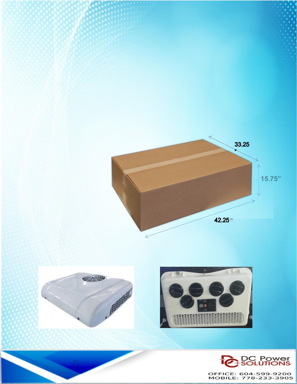
AC shipping box 107.5cm x 84.5cm x
40cm (42.3 x 33.25 x
15.75 inches)
107.5cm x 84.5cm x
40cm (42.3 x 33.25 x
15.75 inches)
7
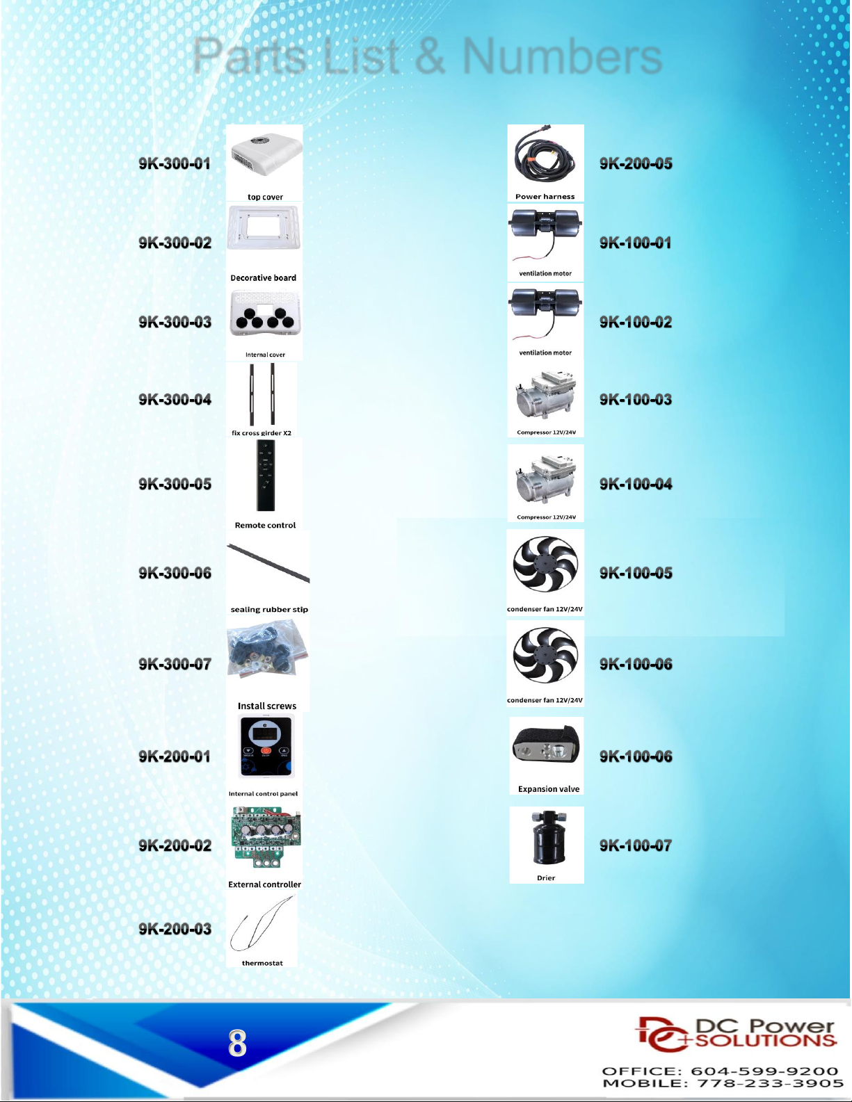
Parts List & Numbers
8
Installation
Installation Conditions:
1. Read the Installat on sect on to understand how the un t s mounted and nstalled before start ng.
2. Mount ng surfaces must be clean and free of debr s.
3. Gather all equ pment needed for the nstallat on.
4. Ver fy roof s strong enough to support the roof mount AC un t and the we ght.
5. Please look to techn cal spec f cat ons for we ght and space requ rements
6. Make sure there s no nterference w th any OEM electr cal w r ng, supports, etc. before
dr ll ng or cutt ng nto the veh cle.
7. D scuss w th customer or cons der appl cat on, keep ng mportant spaces open and enough
clearance at doors / roof for easy use of the system.
8. Prepare add t onal mount ng hardware s nce there are d fferences between veh cle types,
models, and appl cat ons.
Useful tools & equipment
• Tape measure
• Ut l ty kn fe
• Dr ll/Impact gun
• Dr ll b t set
• Angle gr nder
• Wrench set
• Pl ers
• W re cutters
• W re cr mpers
Installation (Roof-top Unit)
Ma n components of One-P ece a r cond t oner
8
”
15.75”
9

Installation Instructions For B-COOL9000
MODEL #
B-COOL9000RM12V & B-COOL9000RM24V
Roof top hole - MAXIMUM. cut size
75cm x 50cm (29.5in. x 19.7in.)
Roof top hole - MINIMUM cut size
62cm x 36cm ---OR--- 24.4 x 14.2 inches
Once the cut is made, clean the area around the hole.
Remove all dust & dirt.
Apply sealant tape around the cut hole
Make sure there are no wrinkles or twist in the sealant tape
Before Installation
Place the air conditioner on the roof.
Keep in mind - the unit weighs 34.5kg or 76lbs. Get someone
to help you.
Fit the air conditioner over the cut-out area.
Attach the air conditioner with the 2 cross bars provided.
Last, install the decorative cover with the parts provided.
Connect the power wire to the automotive battery.
Run the power cables from the main or auxiliary batteries.
Check the polarity before installing the cables
Use the provided 100A Maxi type fuse between the vehicle
battery and the positive main wire
10
1
ERROR Codes displayed on the controller
If, while the air conditioner is running, any of the following codes appear on the
controller screen, please take the following steps as the code may indicate a serious
problem
1: STOP THE AIR CONDITIONER & POWER OFF.
2: AFTER 10 MINUTES POWER ON & START A/C
3: IF THE CODE PERSISTS - STOP A/C & POWER OFF
4: CONTACT REPAIR CENTER.
E01 - Voltage is too low - Charge the battery or Start the Eng ne
E02 - Evaporator blower is not operating. Check w r ng and voltage of the supply w r ng and repa r.
Also check blower and replace f defect ve.
H22 / H23 - Check evaporator nlet sensor by power ng down the a r cond t oner and restart the a r
cond t oner. If the code reappears t means that the sensor s defect ve or has become d slodged from the
evaporator co l.
E04 - Temperature sensor of the plenum
E05 - Compressor over temperature indicator. Th s w ll power off the un t unt l to compressor cools
down so as not to damage the un t. Th s may happen f the amb ent temperature s very h gh. Once the
compressor cools the un t w ll restart aga n.
E06 / E07 - Condenser fan is not operating. Check the w r ng and voltage. Also check fan as t may be
defect ve and needs to be replaced
E09 - Condenser fan control board s defect ve and should be replaced.
E10 - Condenser fan fa lure - Replace the condens ng fan motor
E11 - The condenser fan is not operating. Check the w r ng for damage.
NOTE: If the number flashing on the indicator is not shown in this table, please replace the
compressor control panel
11
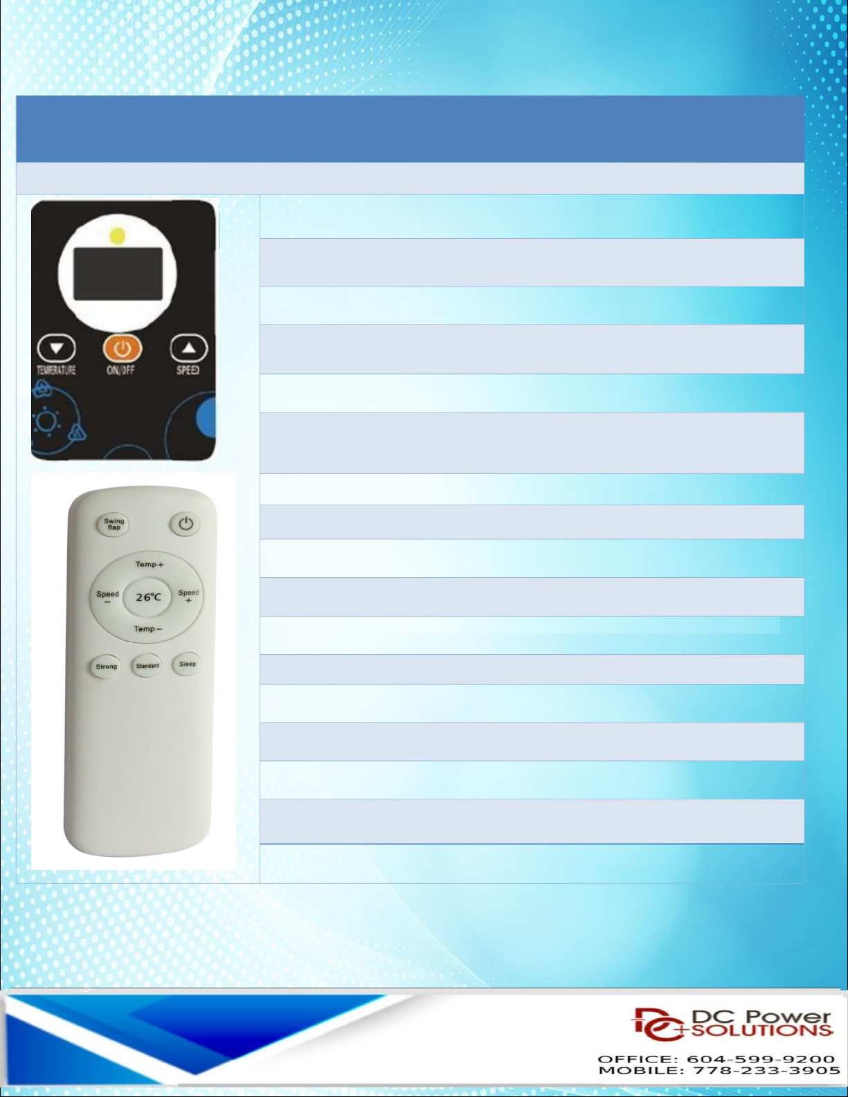
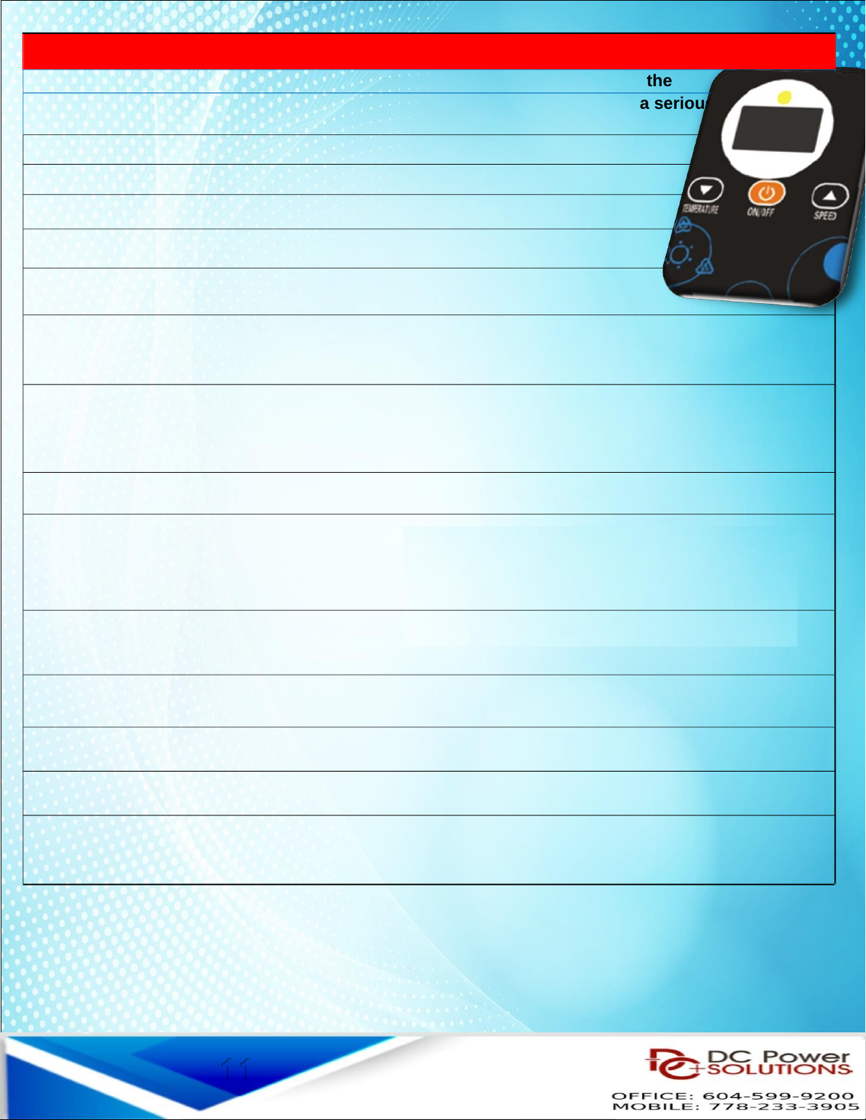
OPERATING INSTRUCTIONS
Functions of the Control panel & the Remote Control
Turn on A/C: Press On / Off button to turn on A/C (long press)
Check H gh/Low Pressure
Normal range: H/P 1.2 - 1.4 L/P 0.2 - 0.25
Temperature setting:
A) Cl ck the Temp. button (Arrow down) to set the temperature after
start ng the A r Cond t oner
B) After cl ck ng the down button, cl ck the DOWN button
or the UP button to set des red temperature (18°C [66°F] – or h gher)
Speed setting:
A) Cl ck the Speed button (Arrow up) to set speed after start ng the A r
Cond t oner
B) After cl ck ng the up button, cl ck the DOWN button or
the UP button to adjust the speed
Voltage setting:
A) After start ng the A r Cond t oner, cl ck the ON / OFF
button 3 t mes to enter the voltage sett ng
B) Cl ck the DOWN button or the UP button to set the
voltage
NOTE: Sw ng Flap, T med off , T med on – NO FUNCTION
12

Compressor Troubleshooting
Flash 1x
Standby
5x
Compressor Case temperature is too high- Lack of
refrigerant or dirty condenser
6x
Open circuit of cooling fan - Bad contact of
electromagnetic fan plug
7
x
Short circuit of cooling fan - Short circuit in the motor or
short circuit in the connection line.
9x
Condenser fan controller failure
10x
Condenser fan failure
11x
Condenser fan lost contact
13
Troubleshooting - Air conditioners
If any of the following situations occur during the use of air
conditioners, please find out a solution by following the index
If it’s a fault, Please contact the tech. / repair center.
Condition Solution
If the cooling
effect is not good
Select the right mode and set proper temperature and speed.
Check if there is any obstruction at the air inlet and outlet
Check if the surface of the condenser is too dirty
Check if it is short of refrigerant and if the high and low
voltage is within the normal range
There is water on
the surface of
indoor unit
When running in an environment with high humidity, water
drops may form on at the air outlet and core surface, which
is a normal physical phenomenon
Check battery for low voltage and verify the power source is
either DC 12V or 24V
The indoor unit
displays voltage
fault
Check if the low voltage protection value is too high
Check if the sensor at air inlet / outlet is plugged in correctly
The indoor unit
displays sensor
fault
Check if the display temperature is higher than normal
ambient temperature. If it is, change the sensor.
The indoor
unit displays fan
fault
Check if the fan is correctly plugged in. Connect the fan with
a separate 12V or 24V DC power source. If the fan doesn’t
work, replace fan.
Installation and User Manual for vehicle Electric Air – Conditioners
The indoor unit
displays outdoor unit
fault
Check if it is short of refrigerant.
Check if the high and low voltage is within the normal range.
Check if the condenser is too dirty - so that heat dissipation
is adversely affected.
14

The -COOL9000 unit comes pre-charged. However, should a leak or an
Incident occur during shipping, the following steps must be taken.
Leak Testing
1 - Refr gerant volume (check w th level glass)
2 - If volume s low or s lower than the prev ous check, nvest gate poss ble
leak by look ng for traces of o l.
3 - Attach the n trogen tank to the low s de port.
4 - Perform a leak test by pressur ng the system to 200 ps and then check for leaks
at each f tt ng and connect on and throughout the evaporator and condenser co ls.
5 - The system should hold pressure for at least 15 m nutes.
6 - Somet mes, but rarely, the un t could be damaged dur ng sh pp ng.
7 - If there are no leaks, evacuate the system.
Evacuate System
Evacuate the ent re system wh le meet ng local refr gerant handl ng standards.
We recommend at least 30-45 m nutes vacuum before charg ng.
After the un t s empty, move to charg ng the system and charge t w th 650g of
R134a refr gerant.
Charge the System
The system should be charged by a qual f ed A/C techn c an and
follow the gu del nes for R134a Freon.
15

Maintenance:
Before beg nn ng clean ng, make sure the a r cond t oner s
turned off, powered off
1) Surface Cleaning of inside unit:
W pe w th a clean damp cloth.
The cloth can be d pped n a m ld clean ng solut on f the un t s very d rty.
2) The core of evaporation chamber is too dirty.
Check for d rt and debr s n the evaporator, clean w th compressed a r f
necessary.
3) Outdoor unit cleaning:
Remove the top cover and clean the condenser w th compressed a r.
Pay attent on not to damage the condenser co l.
4)Long time not in use:
Unplug the a r cond t oner and wrap the outdoor un t to avo d any phys cal
damage
5) Using after long time not in use:
Clean the un t body condenser and evaporat on un t. Check for s gns of any
fore gn matter at the a r nlet or outlet of the un t. Check f the dra n s clear;
Install remote controller, make nspect on and power t on.
Tips:
Maintain the AC unit frequently - at least once every 2 months,
If you operate the AC in a dusty - dirty environment more
frequent cleaning will be required.
Check for blockage on top and bottom of the condenser fan,
the condenser coil and air flow before and after the evaporator
blower.
16
Other manuals for B-COOL9000RM-12V
1
This manual suits for next models
1
Table of contents
Other DC Power Solutions Automobile Accessories manuals


