DC Power Solutions B-COOL12000WMB 12V User manual
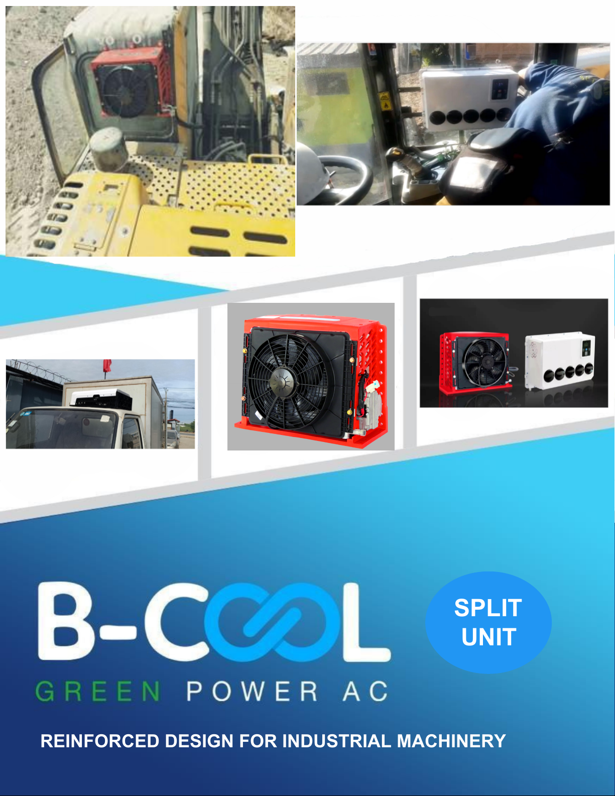
REINFORCED DESIGN FOR INDUSTRIAL MACHINERY
SPLIT
UNIT

INDEX:
Introduction & Company Information ...........................3
Safety instructions…............................................................4
B-COOL SPU Specifications… ..........................................5
Parts List & Numbers …………………………………….. 6
Parts List & Numbers Continued……………………….. 7
Installation………………………………………………….. 8
Technical & Install Specifications………………………. 9
Operating Instructions…………………………………… 10
Fault Analysis …………………………………………….. 11
Compressor / Trouble Shooting……………………….. 12
Refrigerant Leakage……………………………………... 13
Maintenance………………………………………………. 14

Introduction
B-COOL Split Unit Is an AC unit, available in 12 and 24 voltswith an inside cab air diffuser, ready to
connect wire harness / battery cable and fuse block and comes pre- charged with R134a refrigerant.
In other words –our unit comes completely ready to go.
DC Power Solutions provides this document for informational purposes only. DC Power Solutions has devoted
significant time and effort to compile manuals (Installation, Maintenance and Troubleshooting) to assist customers
with the installation of the AC and product usage. However, DC Power Solutions makes no representations
warranties expressed or implied with respect totheinformation, recommendation s and descriptions contained within
this andother documents. Information from the manuals should at no time be regarded as covering all contingencies.
If you are in need of additional information, contact DC Power Solutions directly.
DC Power Solution’s warranty shall not apply toany product which has beeninstalled, maintained, repaired or altered
in a manner as to affect the product’s integrity. Any alteration of these products and deviation from suggested
installation process without written approval will void DC Power solution’s warranty.
DC Power Solutions accepts no liability to any person or entity for personal injury of any kind, property damage, or
any other direct, indirect, special, or consequential damages whatsoever arising out of the use of the manuals or
deriving from any information, recommendations or descriptions contained in the manuals.
To ensure the durability of DC Power Solutions products, please follow and understand the instructions within the
manuals.
Recycle and dispose of the air conditioning unit properly to help keep the environment healthy.
There are Federal, Provincial and State regulations regarding the disposal of refrigeration /AC machines. Consult a
professional and ensure they follow the laws when disposing of the refrigeration/ACunit.
SALES
OFFICE:604-599-9200
MOBILE:778-233-3905
For Sales Information:
sandersen@dcpowersales.com
sales@dcpowersales.com
MAILING ADDRESS
P.O. Box 84556
101-12080 Nordel Way
Surrey BC, CANADA
V3W6Y7
3

Recommendations / Safety Instructions
The installation must be performed by a
qualified professional.
Switch off / disconnect the battery before
installation and performing maintenance work.
Wear goggles and gloves for the installation of
this product or disassembly an item for repair.
ATTENTION: The unit must be cooled before any
work is performed. Some parts are hot and can cause
burns.
ATTENTION. Do not remove any protection
provided on the unit. This could cause serious injury.
ATTENTION: The unit is heavy. Do not handle
or install the unit alone.
4

B-COOL12000WMB –SPLIT UNIT -
100% Electric
MODEL #
B-COOL12000WMB 12V
B-COOL12000WMB 24V
Voltage
12V
24V
Compressor type
DC scroll frequency
compressor
DC scroll frequency
compressor
Max. current
80amps
50 amps
Working current
60-80 amps
15-50 amps
Working Time
(Parked Vehicle)
6-8 Hours
6-8 Hours
Freon type
R134a
R134a
Freon amount
600-650g
600-650g
Cooling capacity
12,000 BTU/h
12,000 BTU/h
Evaporator air
flow
600m³/hr
600m³/hr
Condenser air
flow
2400m³/hr (1410cfm)
2400m³/hr (1410cfm)
Climate controller
yes
yes
Remote
controller
yes
yes
AC Outside
dimensions
53cm L x 44cm W x 22cm H
(20.86 x 17.32 x 8.66 inches)
53cm L x 44cm W x 22cm H
(20.86 x 17.32 x 8.66 inches)
AC inside cabin
dimensions
Weight of
Compressor,
condenser
45cm L x 33.5cm W x 16.5cm H
(17.72 x 13.2 x 6.49 inches)
24 kg (52.91 lbs.)
45cm L x 33.5cm W x 16.5cm H
(17.72 x 13.2 x 6.49 inches)
24 kg (52.91 lbs.)
Weight of
Evaporator
6.2 kg (13.66 lbs.)
6.2 kg (13.66 lbs.)
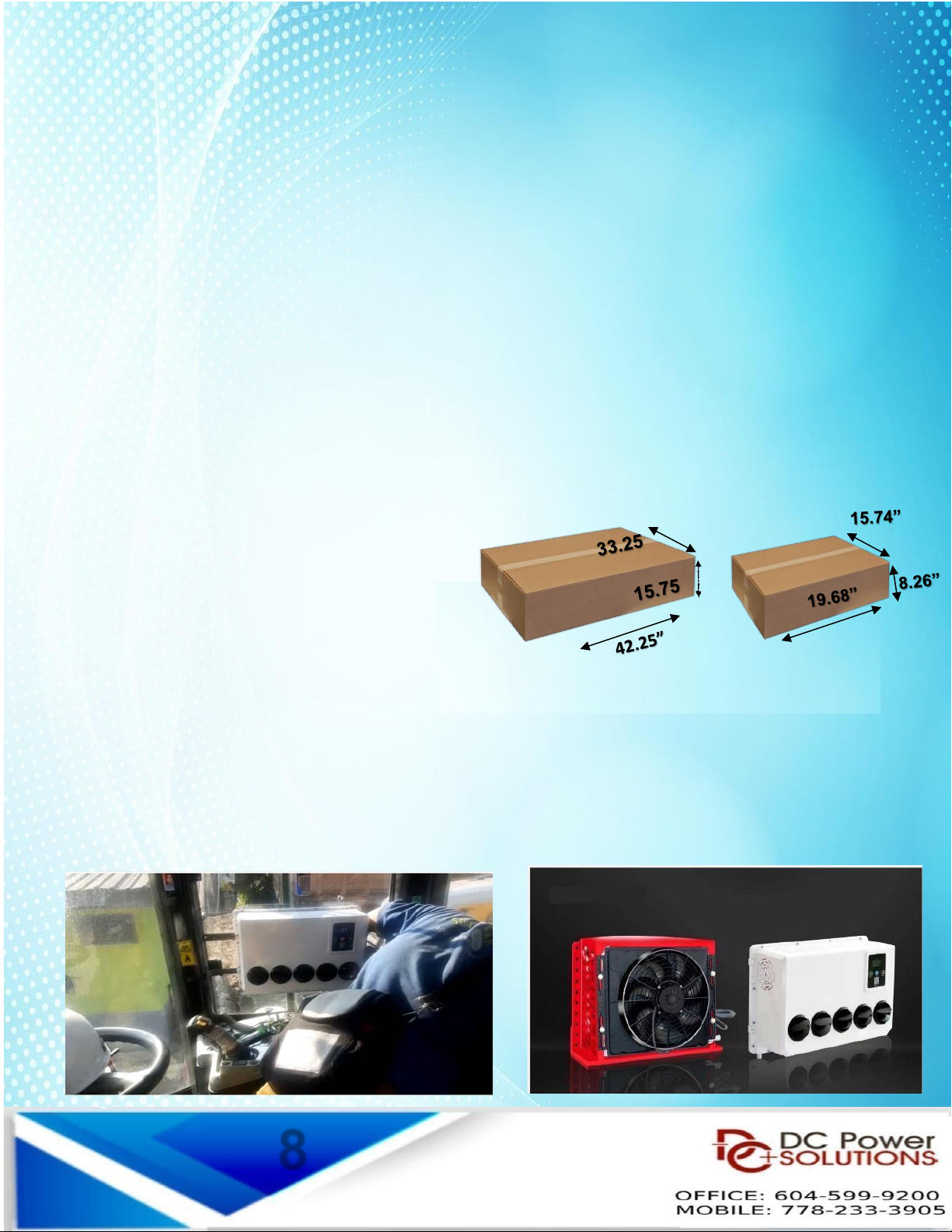
AC shipping box 1
AC shipping box 2
60cm x 50cm x 30cm
(23.62 x 19.68 x 11.811 inches)
50cm x 40cm x 21cm
(19.68 x 15.74 x 8.26 inches)
60cm x 50cm x 30cm
(23.62 x 19.68 x 11.811 inches)
50cm x 40cm x 21cm
(19.68 x 15.74 x 8.26 inches)
5

PARTS LIST & NUMBERS
SPU –BOX-TYPE
PLASTIC
ENCLOSURE
SPU –BOX-TYPE
UPPER COVER
SPU -
CONDENSER FAN
SPU –CONDENSER
SPU –BOX-TYPE
HIGH PRESSURE
PIPE
SPU –
COMPRESSOR
SHOCK PAD
SPU –INJECTION
MOLDDING
CONNECTION LINE
SPU –3 POINT
HOSE
SPU –300-02 ---------- 1X
SPU –100-05 (12V) ---------- 1X
SPU –100-06 (24V) ---------- 1X
SPU –100-11 –4X
6
SPU –300-01 ---------- 1X
SPU –100-13 –1X
SPU –100-12 –1X
SPU –100-09 ---------- 1X
SPU –100-10 ---------- 1X

SPU –5
POINT HOSE
SPU –POWER
HARNESS
SPU –CONTROL
HARNESS
SPU –
COMPRESSOR
CONTROLLER
SPU –
COMPRESSOR
12V / 24V
SPU –BOX-TYPE
SPU –100-14 –1X
SPU –100-15 –1X
SPU –100-16 –1X
SPU –100-17 –1X
SPU –100-18 –1X
SPU –100-19 –1X
7
PARTS LIST & NUMBERS
Installation
Pre-Install:
1. Open both the boxes and first check all the components and parts are present.
2. Read the Installation section to understand how the unit is mounted and installed before starting.
3. Mounting surfaces must be clean and free of debris.
4. Gather all equipment needed for the installation.
5. Verify roof is strong enough to support the roof mount AC unit and the weight.
6. Please look to technical specifications for weight and space requirements
7. Make sure there is no interference with any OEM electrical wiring, supports, etc.before
drilling or cutting into the vehicle.
8. Prepare additional mounting hardware since there are differences between vehicletypes,
models, and applications.
Useful tools & equipment
•
Tape measure
•
Utility knife
•
Drill/Impact gun
•
Drill bit set
•
Angle grinder
•
Wrench set
•
Pliers
•
Wire cutters
•
Wire crimpers
•
Pull Riveter
8

Installation Instructions For B-COOL12000SPU
MODEL #
B-COOL12000WMB 12V & 24V
Keep in mind the outside machine weighs 24 Kgs or 53lbs,
Get someone to help you.
Place the Air conditioner in the desired position.
Select the installation position and mark spot where to
punch the holes.
Use a pull riveter to fix the pull nut at the marked hole.
Install the shock absorption washer.
Attach the inside (evaporator) mounting plate
Now attach the evaporator - it weighs 6.2Kgs or 13.6lbs.
Install the expansion Valve.
Cut a hole(50mm) to connect internal and external
Units.
Connect the Pipe/ Hose provided.
Vacuum and Re-Fill the Freon for 30-45 minutes.
(R134a 650-700g).
Run the power cables to the main battery or auxiliary
batteries.
Check the polarity before installing the cables
Connect the power wire to the automotive battery.
Enjoy Cool Air.
9

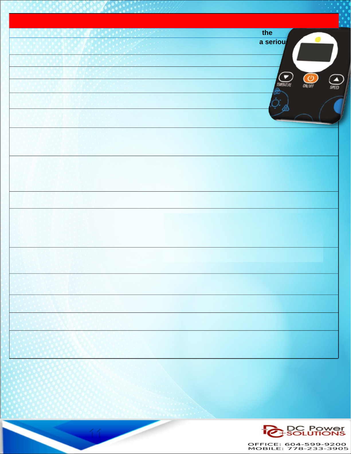
OPERATING INSTRUCTIONS
Functions of the Control panel & the Remote Control
Turn on A/C: Press On / Off button to turn on A/C (long press)
Check High/Low Pressure
Normal range: H/P 1.2 - 1.4 L/P 0.2 - 0.25
Temperature setting:
A) Click the Temp. button (Arrow down) to set the temperature after
starting the Air Conditioner
B) After clicking the down button, click the DOWN button
or the UP button to set desired temperature (18°C [66°F] –or higher)
Speed setting:
A) Click the Speed button (Arrow up) to set speed after starting the Air
Conditioner
B) After clicking the up button, click the DOWN button or
the UP button to adjust the speed
Voltage setting:
A) After starting the Air Conditioner, click the ON / OFF
button 3 times to enter the voltage setting
B) Click the DOWN button or the UP button to set the
voltage
NOTE: Swing Flap, timed off, Timed on –NO FUNCTION
10
1
ERROR Codes displayed on the controller
If, while the air conditioner is running, any of the following codes appear on the
controller screen, please take the following steps as the code may indicate a serious
problem
1: STOP THE AIR CONDITIONER & POWER OFF.
2: AFTER 10 MINUTES POWER ON & START A/C
3: IF THE CODE PERSISTS - STOP A/C & POWER OFF
4: CONTACT REPAIR CENTER.
E01 - Voltage is too low - Charge the battery or Start the Eng ne
E02 - Evaporator blower is not operating. Check w r ng and voltage of the supply w r ng and repa r.
Also check blower and replace f defect ve.
H22 / H23 - Check evaporator nlet sensor by power ng down the a r cond t oner and restart the a r
cond t oner. If the code reappears t means that the sensor s defect ve or has become d slodged from the
evaporator co l.
E04 - Temperature sensor of the plenum
E05 - Compressor over temperature indicator. Th s w ll power off the un t unt l to compressor cools
down so as not to damage the un t. Th s may happen f the amb ent temperature s very h gh. Once the
compressor cools the un t w ll restart aga n.
E06 / E07 - Condenser fan is not operating. Check the w r ng and voltage. Also check fan as t may be
defect ve and needs to be replaced
E09 - Condenser fan control board s defect ve and should be replaced.
E10 - Condenser fan fa lure - Replace the condens ng fan motor
E11 - The condenser fan is not operating. Check the w r ng for damage.
NOTE: If the number flashing on the indicator is not shown in this table, please replace the
compressor control panel
11

Troubleshooting - Air conditioners
If any of the following situations occur during the use of air
conditioners, please find out a solution by following the index
If it’s a fault, please contact the tech. / repair center.
Condition
Solution
If the cooling
effect is not good
Select the right mode and set proper temperature and speed.
Check if there is any obstruction at the air inlet and outlet
Check if the surface of the condenser is too dirty
Check if it is short of refrigerant and if the high and low
voltage is within the normal range
There is water on
the surface of
indoor unit
When running in an environment with high humidity, water
drops may form on at the air outlet and core surface, which
is a normal physical phenomenon
The indoor unit
displays voltage.
fault
Check battery for low voltage and verify the power source is
either DC 12V or 24V
Check if the low voltage protection value is too high
The indoor unit
displays sensor
fault
Check if the sensor at air inlet / outlet is plugged in correctly
Check if the display temperature is higher than normal
ambient temperature. If it is, change the sensor.
The indoor unit
displays fan fault
Check if the fan is correctly plugged in. Connect the fan with
a separate 12V or 24V DC power source. If the fan doesn’t
work, replace fan.
Installation and User Manual for vehicle Electric Air –Conditioners
The indoor unit
displays outdoor unit
fault
Check if it is short of refrigerant.
Check if the high and low voltage is within the normal range.
Check if the condenser is too dirty - so that heat dissipation
is adversely affected.
12

The B-COOL9000 unit comes pre-charged. However, should a leak or
an Incidentoccur during shipping, the following steps must be taken.
Leak Testing
1
- Refrigerant volume (check with level glass)
2
- If volume is low or is lower than the previous check, investigate possible
leak by looking for traces of oil.
3
- Attach the nitrogen tank to the low side port.
4
- Perform a leak test by pressuring the system to 200 psi and then check for leaks
at each fitting and connection and throughout the evaporator and condenser coils.
5 - The system should hold pressure for at least 15 minutes.
6 –Sometimes, but rarely the unit could get damaged during shipping.
7 - If there are no leaks, evacuate the system.
Evacuate System
Evacuate the entire system while meeting local refrigerant handling standards.
We recommend at least 30-45 minutes vacuum before charging.
After the unit is empty, move to charging the system and charge it with 650g of
R134a refrigerant.
Charge the System
The system should be charged by a qualified A/C technician and
follow the guidelines for R134a Freon.
13

Maintenance
Before beginning cleaning, make sure the air conditioner is
turned off, powered off.
1)
Surface Cleaning of inside unit:
Wipe with a clean damp cloth.
The cloth can be dipped in a mild cleaning solution if the unit is very dirty.
2)
The core of evaporation chamber is too dirty.
Check for dirt and debris in the evaporator, clean with compressed air
if necessary.
3)
Outdoor unit cleaning:
Remove the top cover and clean the condenser with compressed
air. Pay attention not to damage the condenser coil.
4)
Long time not in use:
Unplug the air conditioner and wrap the outdoor unit to avoid any
physical damage.
5)
Using after long time not in use:
Clean the unit body condenser and evaporation unit. Check for signs of any
foreign matter at the air inlet or outlet of the unit. Check if the drain is
clear; Install remote controller, make inspection and power it on.
Tips:
Maintain the AC unit frequently - at least once every 2 months, If
you operate the AC in a dusty - dirty environment more frequent
cleaning will be required.
Check for blockage on top and bottom of the condenser fan, the
condenser coil and air flow before and after the evaporator
blower.
14
This manual suits for next models
1
Table of contents
Other DC Power Solutions Automobile Accessories manuals


Popular Automobile Accessories manuals by other brands


Suzuki
Suzuki 99177-78R00 installation instructions

Intellitronix
Intellitronix BZ10005 installation guide

Rival
Rival 2333.0334.1 installation manual

LaserLine
LaserLine 921T user manual

TEINHOF
TEINHOF S-397 FITTING AND OPERATION MANUAL

Dakota Digital
Dakota Digital LED Tail Lights for 1969 Mustang LAT-NR372 installation instructions