DCA Z1G-FF-15 User manual
Edition 2 July, 2011
Read through carefully and understand these instructions
before use.

GENERAL SAFETY RULES
(ForAll Tools)
WARNING! Read and understand all instructions. Failure to
follow all instructions listed below may result in electric shock, fire
and/or serious personal injury.
Work Area
1. Keep work area clean and well lit. Cluttered areas and benches invite
injuries.
2. Do not operate power tools in explosive atmospheres, such as in the
presence of flammable liquids, gases, or dust. Power tools create sparks
which may ignite the dust or fumes.
3. Keep bystanders, children, and visitors away while operating a power
tool. Distractions can cause you to lose control.
Electrical Safety
4. Power tools must be plugged into an outlet properly installed or
grounded in accordance with all codes and ordinances. Never modify
the plug in any way. Do not use any adaptor plugs with grounded
(earthed) power tools. The original plug and proper outlet may reduce the
risk of electric shock.
5. Avoid body contact with grounded surfaces such as pipes, radiators,
ranges and refrigerators. There is an increased risk of electric shock if your
body is grounded.
6. Do not expose power tools to rain or wet conditions. Water entering a
power tool will increase the risk of electric shock.
7. Do not abuse the cord. Never use the cord to carry the tools or pull the
plug from an outlet. Keep cord away from heat, oil, sharp edges or
moving parts. Replace damaged cords immediately. Damaged or entangled
cords increase the risk of electric shock.
8. When operating a power tool outside, use only extension cords intended
for outdoors use. These cords may reduce the risk of electric shock.
Personal Safety
9. Stay alert, watch what you are doing and use common sense when operating
a power tool. Do not use tool while tired or under the influence of drugs,
alcohol, or medication. A moment of inattention while operating power tools may
result in serious personal injury.
10.Dress properly. Do not wear loose clothing or jewelry. Contain long hair.
Keep your hair, clothing, and gloves away from moving parts. Loose clothes,
jewelry, or long hair can be caught in moving parts.
11.Avoid accidental starting. Be sure switch is off before plugging in. Carrying
tools with your finger on the switch or plugging in tools that have the switch on invites
accidents.
12.Remove adjusting keys or wrenches before turning the tool on. A wrench or a
key that is left attached to a rotating part of the tool may result in personal injury.
13.Do not overreach. Keep proper footing and balance at all times. Proper footing
and balance enables better control of the tool in unexpected situations.
14.Use safety equipment. Always wear eye protection. Dust mask, non-skid safety
shoes, hard hat, or hearing protection must be used for appropriate conditions.
Ordinary eye or sun glasses are NOT eye protection.
15.If devices are provided for the connection of dust extraction and collection
facilities, ensure these are connected and properlyused. Use of dust collection
can reduce dust-related hazards.
Tool Use and Care
16.Do not force tool. Use the correct tool for your application. The correct tool will
do the job better and safer at the rate for which it is designed.
17.Do not use tool if switch does not turn it on or off. Any tool that cannot be
controlled with the switch is dangerous and must be repaired.
18.Disconnect the plug from the power source before making any adjustments,
changing accessories, or storing the tool. Such preventive safety measures
reduce the risk of starting the tool accidentally.
19.Store idle tools out of reach of children and other untrained persons. Tools
are dangerous in the hands of untrained users.
-1- -2-

20. Maintain tools with care. Keep cutting tools sharp and clean. Properly
maintained tools with sharp cutting edges are less likely to bind and are
easier to control.
21. Check for misalignment or binding of moving parts, breakage of parts,
and any other condition that may affect the tools operation. If damaged,
have the tool serviced before using. Many accidents are caused by poorly
maintained tools.
22. Use only accessories that are recommended by the manufacturer for
your model. Accessories that may be suitable for one tool, may become
hazardous when used on another tool.
Ser ice
23. Tool service must be performed only by qualified repair personnel.
Service or maintenance performed by unqualified personnel could result in a
risk of injury.
24. When servicing a tool, use only identical replacement parts. Follow
instructions in the Maintenance section of this manual.
Use of
unauthorized parts or failure to follow Maintenance instructions may create a
risk of electric shock or injury.
VOLTAGE WARNING:
Before connecting the tool to a power source (receptacle, outlet, etc.), be sure the
voltage supplied is the same as that specified on the nameplate of the tool. A
power source with voltage greater than that specified for the tool can result in
SERIOUS INJURY to the user, as well as damage to the tool. If in doubt, DO NOT
PLUG IN THE TOOL. Using a power source with voltage less than nameplate
rating is harmful to the motor.
SPECIFICATIONS
Rated Power Input 1240 W
Blows per Minute 1400 …/min
Net Weight 16 kg
※Due to the continuing program of research and development, the specifications
herein are subject to change without prior notice.
ADDITIONAL SAFETY RULES
1. Be sure to wear a safety helmet. Also wear ear protectors, safety glasses, face
shield and/or thickly padded gloves when necessary.
2. Check and ensure that the bit be correctly installed and secured before operation.
3. Hold tools by insulated gripping surfaces when performing an operation where the
cutting tool may contact hidden wiring or its own cord. Contact with a “live” wire will
make exposed metal parts of the tool “live” and shock the operator.
4. Vibration will be occurred in normal operation according to the design. That will
cause the screws easy to be loosened and invite damages and accidents. Check
tightness of screws carefully before operation.
5. In cold weather or when the tool has not been used for a long time, let the tool
warm up for a while by operating it under no load. This will loosen up lubrication.
Without proper warm-up, hammering operation is difficult.
6. Always be sure to have a firm footing. Use safety belt and be sure no one is below
when using the tool in high locations.
7. Always use the auxiliary handle and hold the tool firmly with both hands.
8. Keep hands away from the rotating parts.
9. Do not leave the tool running. Operate the tool only when hand-held.
10.Do not point the tool at anyone in the area when operating. The bit could fly out and
injure someone seriously.
-3- -4-
11. Do not touch the bit or parts close to the bit immediately after operation; they
may be extremely hot and could burn your skin.
12. Some material contains chemicals which may be toxic. Take caution to
prevent dust inhalation and skin contact. Follow material supplier safety
data.
SAVE THESE INSTRUCTIONS.
WARNING! MISUSE or failure to follow the safety rules stated in this
instruction manual may cause serious personal injury.
INSTRUCTIONS FOR OPERATION
1.
..
.
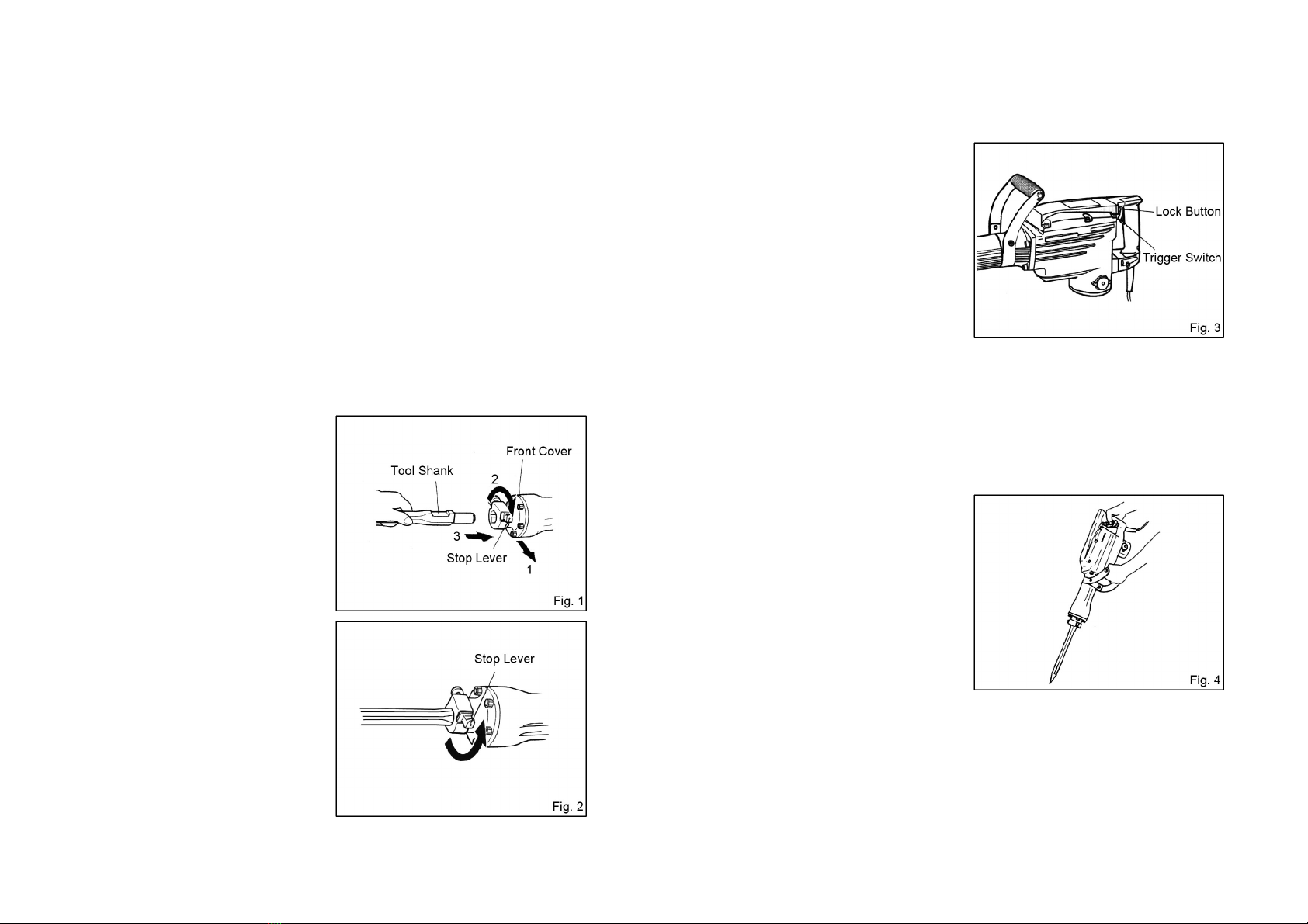
Installing or Remo ing the Bit
CAUTION: Always be sure that the tool is switched OFF and unplugged
before installing or removing the
bit.
Clean the bit shank and smear it
with grease or machine oil before
installation.
To install the bit, rotate the stop
lever 180°in a clockwise direction
while pulling it toward you. Then
insert the bit shank into the
hexagonal hole on the front cover.
(Fig. 1)
Clamp the tool by turning the stop
lever by half a turn in the opposite
direction. (Fig. 2)
To remove the bit, follow the
installation procedure in reverse.
2.
..
.
Switch Operation
CAUTION: Before plugging in the tool, always check to see that the trigger switch
actuates properly and returns to the “OFF” position when released.
To start the tool, simply pull the switch
trigger. Release the trigger to stop. For
continuous operation, pull the switch
trigger and then push in the lock button.
To stop the tool from the locked position,
press the switch trigger fully, then
release it. (Fig. 3)
3.
..
.
Chipping/Scaling/Demolition
Pull the trigger switch after applying the tip of the bit to the crushing position. In
some cases, it is necessary to punch the tip of the bit against the crushing position
forcibly in order to begin the striking motion. This is not due to malfunction of the
tool. It means that the safe guard
mechanism against no-load striking is
working.
Operate the tool by utilizing its empty
weight. The performance will not be
better even if the tool is pressed or
thrust forcibly against the work surface.
Hold the tool with a force just sufficient
to counteract the reaction. (Fig. 4)
CAUTION:
Sometimes the tool does not begin the striking motion even when the motor
rotates because the oil has become thick.
If the tool is used at low temperatures or if it is used after a long time idle, the
tool should be used running in for five minutes in order to warm it up.
-5- -6-
4.
..
.
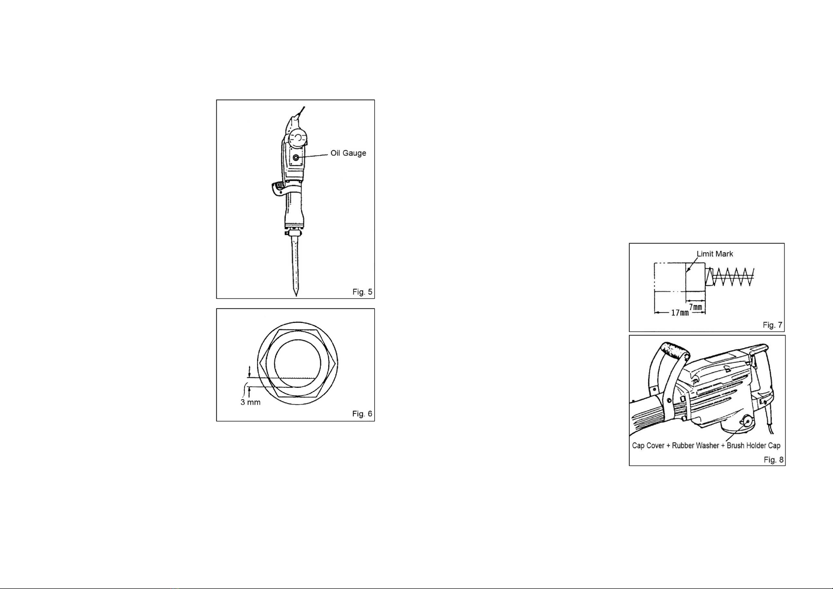
Oil Feeding
CAUTION: Prior to oil feeding, always disconnect the plug from the
receptacle.
Since an oil chamber is built in this
tool, it can be used for approximately
20 days without replenishing
lubrication oil, assuming that the tool
is used continuously 3-4 hours daily.
(Fig. 5)
Feed oil into the oil tank as
described below before using this
tool.
Just before the oil level, which
can be visible in the oil gauge
window, is decreasing lower
than 3 mm when the power tool
is held upright, feed oil without
fail. (Fig. 6)
Before feeding oil, use the
provided wrench to remove the
oil gauge. Be careful not to lose
the rubber packing attached
below the oil gauge.
After feeding oil, securely clamp
the oil gauge.
Check the oil level once a day, confirming that oil is filled.
NOTE:
As an optional accessory, the oil is sold separately. Shell Oil Co. ROTELLA
#40 (engine oil) can also be used. This oil is sold as Shell gasoline stations
most anywhere.
MAINTENANCE AND INSPECTION
CAUTION:
Always be sure that the tool is switched off and unplugged before attempting to
perform inspection or maintenance.
1.
..
.
Inspecting the Bit
Since use of a dull bit will degrade efficiency and cause possible motor malfunction,
sharpen or replace the bit as soon as abrasion is noted.
2.
..
.
Inspecting the Mounting Screws
Regularly inspect all mounting screws and ensure that they are properly tightened.
Should any of the screws be loose, retighten them immediately. Failure to do so
could result in serious hazard.
3.
..
.
Inspecting and Replacing Carbon Brushes
Remove and check the carbon brushes
regularly. Replace when they wear down
less than 7 mm (Fig. 7). Keep the carbon
brushes clean and free to slip in the
holders. Both carbon brushes should be
replaced at the same time. Use only
identical carbon brushes.
Loosen the screw of the cap covers,
remove the cap covers, rubber washers
and brush holder caps in order. Take out
the worn carbon brushes, insert new ones
and secure the brush holder caps, then
mount the rubber washers and cap covers
securely. (Fig. 8)
※
※※
※ To maintain product SAFETY and RELIABILITY, repairs, any other maintenance or
adjustment should be performed by authorized centers, always using original
replacement parts.
-7- -8-
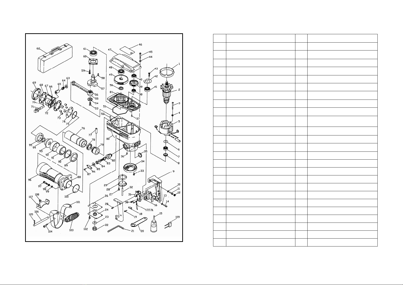
EXPLAINATION OF GENERAL VIEW
1 Baffle Plate 26 Cover Seal
2 Armature Assembly 27 Pan Head Screw M4×10
3 Pan Head Tapping Screw ST4.8×63
28 Oil Cap
4 Screw Cover 29 Rubber Seal
5 Stator Assembly 30 Pan Head Tapping Screw
6 Flat Washer 31 Trigger Switch
7 Ball Bearing 32 Oil Felt
8 Wave Washer 33 Hex Socket Head Screw M5×12
9 Handle Set 34 Rear Cover
10 Screw Cover 35 Insulation Washer
11 Hex Socket Head Screw 36 Hex Socket Screw with Flat Point
M5×8
12 Screw Cover 37 Lock Pin
13 Screw Cover 38 Ball Bearing
14 Hex Socket Head Screw M6×25 39 2
#
Gear
15 Lubricant Oiler 40 Ball Bearing
16 Switch Cover 41 Ball Bearing
17 Cord 42 Bearing Retainer
17A
Cord Guard 43 Hex Socket Head Screw M5×12
18 Strain Relief 44 Spring Lock Washer
19 PanHeadTappingScrewST4×16
45 Hex Socket Head Screw M6×45
20 Wrench 46 Nameplate
21 Hex Wrench 47 Gear Housing Cover
22 Oil Gauge 48 Ball Bearing
23 Oil Seal 49 3
#
Gear
24 Cover Plate 50 Guide Washer
25 Pan Head Tapping Screw ST4.2×20
51 Hexagon Seal
-9- -10-

EXPLAINATION OF GENERAL VIEW
52
Guide Pin 81
Gear Housing
53
Hex Socket Head Screw M8×20
82
Carbon Brush Holder
54
Metal Plate 83
Carbon Brush
55
Connecting Rod 84
Brush Holder Cap
56
Needle Bearing 85
Rubber Washer
57
Crank Shaft 86
Brush Holder Cap Cover
58
Woodruff Key 87
Pan Head Screw M4×10
59
Hex Socket Head Screw M5×16 88
Fiber Washer
60
Bearing Retainer 89
Nylon Seal
61
Ball Bearing 90
Washer
62
Steel Case 91
Rubber Sleeve
63
Flat Washer 92
Snap Washer
64
Compression Spring 93
Shank Sleeve
65
Spring Retainer 94
O Ring
66
Flat Washer 95
Nylon Seal
67
Hex Socket Head Screw M8×40 96
Cylinder Case
68
Six-Hole Rubber Pad 97
Hex Socket Head Screw M8×35
69
Rear Cover 98
Spring Washer
70
Roll Pin 99
Washer
71
Stopper Lever 100
O Ring
72
Cap 101
Auxiliary Handle
73
Iron Sleeve 102
Hex Socket Head Screw M5×12
74
Six-Hole Shim 103
Grip
75
O Ring 104
Hex Socket Head Screw M8×16
76
Cylinder 105
Split Pin
77
Piston Pin 106
Auxiliary Handle Shaft
78
Seal 107
Auxiliary Handle Holder
79
Piston 108
Hex Nut M8
80
Motor Housing 109
Capacitor
-11-
Table of contents
Popular Tools manuals by other brands


Tsubaki
Tsubaki BS-F Series Installation and maintenance manual

Parkside
Parkside 73785 Operation and safety notes translation of original operation manual

Current Tools
Current Tools 615 Operating, Maintenance, Safety and Parts Manual

MSW
MSW MSW-OPG-12.2 user manual

Hilti
Hilti DD 30-W manual

Macnaught
Macnaught MAN1915-01 manual