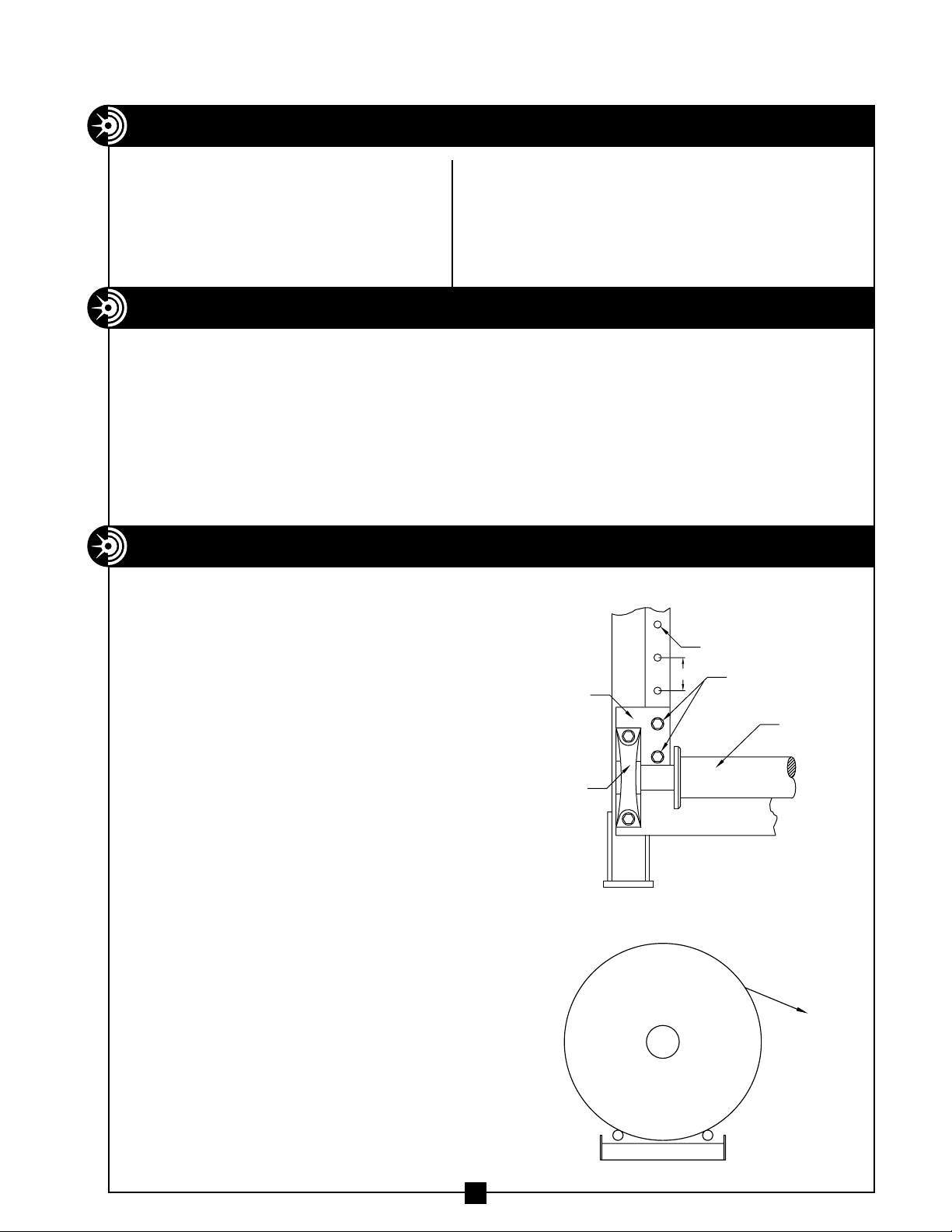
manuals.online logo
Brands
  1. Home
  2. •
  3. Brands
  4. •
  5. Current Tools
  6. •
  7. Tools
  8. •
  9. Current Tools 615 User manual

Current Tools 615 User manual

CURRENT TOOLS • P. O. BOX 17026 GREENVILLE, SC 29606
800.230.5421 or 864-721-4230 • FAX 864-721-4232
www.currenttools.com
Model 615 Cable Reel Roller
with 615-113 Motor
Operating, Maintenance, Safety
and Parts Manual
04/22
This manual is free of charge. All personnel who operate the Cable Reel Roller
should have a copy of this manual and read and understand its contents. To
request a copy, call or write to the address below. All information, specifications
and product designs may change due to design improvements or updates and
are subject to change without notice. Current Tools does not assume any liability
for damages resulting from misuse or incorrect application of its products.
Read and understand this material before operating
or servicing the Cable Reel Roller. Failure to
understand how to safely operate and service this
unit may result in serious injury or death.
SAFETY INFORMATION
• ALWAYS place the cable reel roller on a firm, level surface. Be sure the
surface is capable of supporting the full load of the cable reel roller and the
reel of cable.
• ALWAYS remove reel of cable before moving or transporting the cable reel
roller.
• ALWAYS lift the cable reel roller using forklift pockets or by lifting eyes
provided at each corner of the unit.
• NEVER attempt to lift the cable reel roller by the rollers.
• DO NOT operate or store the cable reel roller in wet or damp locations.
DO NOT EXPOSE TO RAIN.
• Only use this unit for its intended purpose as a cable reel roller.
• DO NOT exceed load rating of the cable reel roller.
• ALWAYS inspect the cable reel roller before each use.
• DO NOT operate in explosive atmosphere.
• ALWAYS disconnect the cable reel roller before servicing.
• ALWAYS plug into grounded receptacle that is GFCI protected.
• KEEP all body parts, hair, loose clothing, etc., away from rotating parts and
pinch points.
• DO NOT alter this cable reel roller. Doing so will void the warranty. Guards
and safety features are provided for your protection.
• DO NOT use extension cord longer than 100 ft. Extension cord should be
12 gauge wire with ground.
• When operating, operator should stand to the side of the cable reel roller
and out of the path of the cable.
2
TABLE OF CONTENTS
This manual should be read and understood by all personnel who operate
or service this Cable Reel Roller. Failure to understand how to operate
and service this equipment could result in injury or death. This Cable Reel
Roller should only be operated by qualified personnel.
Safety Alerts ....................................................... 2
Specifications & Features ............................................ 3
Operating Instructions ............................................... 3
615-255 Motor Assembly Exploded View and Parts List ................... 4
615-255 Motor Assembly Installation..................................5,6
Maintenance ....................................................... 7
Wiring Schematic ................................................... 7
Roller Position Chart ................................................ 8
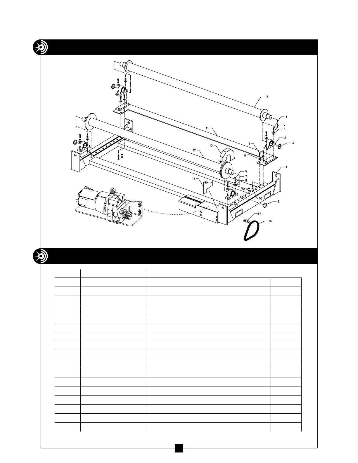
Exploded View and Parts List — Frame and Rollers....................... 9
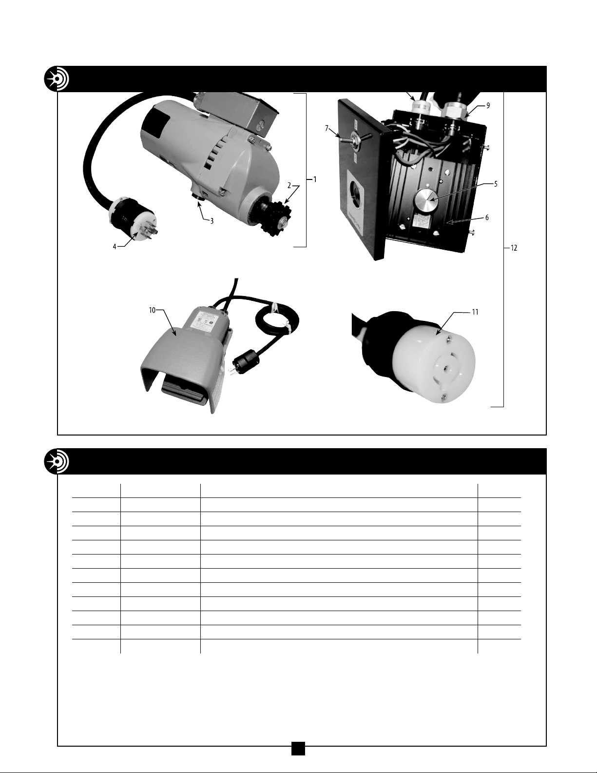
Major Components and Parts List .................................... 10
width — 122"
length — 603⁄4"
height — 19"
weight — 2,800 lbs.
maximum 12' diameter
reel size — 96" width, 15 tons
motor specs — 120 volts, 11.5 amps
BENDING
1.Move the cable reel roller into position for
operation using the forklift pockets on the
sides of the unit, or by the lifting eyes
provided at each corner of the unit.
2. Locate the cable reel roller on a surface
capable of supporting the combined weight
of the unit plus the reel of cable.
3. Adjust the distance between the rollers.
(See Idler Roller Position Chart on pg. 8)
Remove the four adjusting bolts (2 each
side) connecting the idler roller plate to the
reel roller base. Slide the idler roller
assembly to the desired position and
replace the 4 bolts. See figure 1.
4. Load the cable reel onto the cable reel
roller such that the cable feeds from the top
of the reel. See figure 2.
5. Use the hand-held control to set forward or
reverse as required and to adjust the
operating speed of the unit.
6. After making the adjustments with the hand
controls, a foot control is provided to switch
the unit off and on remotely.
7. Always place the controls so that the
operator is clear of the path of the
unwinding cable.
BENDING
• Heavy duty welded frame
for strength and durability
• Heavy duty self-aligning
pillow block bearings
• Pendant control can be
easily disconnected for
safe storage
ADJU
S
TING B
O
LT
S
F
O
R
IDLER R
O
LLER L
O
CATI
ON
4 INCHE
S
VIEW FR
O
M AB
O
V
E
C
O
RNER
O
F
CABLE REEL R
O
LLE
R
IDLER R
O
LLE
R
ADJU
S
TING H
O
LE
S
PILL
OW
BL
O
C
K
BEARIN
G
IDLER
R
O
LLE
R
PLATE
figure 1
figure 2
CABLE
FEED
DIRECTION
SPECIFICATIONS
• Speed control for variable
cable feeding rates
• One roller adjusts to
accommodate various
reel sizes
• On/off foot control for
remote operation
• Rugged and durable
drive motor
• Convenient forklift
pockets on both sides
of unit for quick
transport with forklift
FEATURES
OPERATING INSTRUCTIONS
3
615-255 MOTOR ASSEMBLY EXPLODED VIEW (WITH 615-113 MOTOR)
4
615-255
ASSEMBLED VIEW
(SHOWN OUTSIDE OF MOUNTING
LOCATION ON 615 FRAME)
ITEM # PART # DESCRIPTION Q T Y.
1615-113 4262 MOTOR WITH SPROCKET 1
2615-252 ADJUSTING PLATE – 4262 MOTOR 1
3615-156 JACK SCREW — 615 DRIVE 1
4615-33 SCREW–HEX HEAD CAP GR5 ZINC (1/2"-13×2") 1
5450-1A 1/4-20 ×.75 HHCS 4
6450-14G WASHER–LOCK 1/4 4
7450-14IWASHER – FLAT ZINC 1/4" (USS) 4
8524-11 3/8-16 ×1.0" HEX HEAD SCREW 4
9506-3 WASHER–FLAT 3/8 (USS) ZINC 2
10 452-27 WASHER–LOCK MEDIUM 3/8 ZINC 4
11 615-29D WASHER–OVERSIZE ZINC 2
615-255 MOTOR ASSEMBLY PARTS LIST (WITH 615-113 MOTOR)
615-255 MOTOR ASSEMBLY INSTALLATION (WITH 615-113 MOTOR)
5
1. Remove the two chain guards, chain, old motor
and adjusting plate from frame of reel roller
2. Install new adjusting plate into the opening such that
the four motor mounting screw slots are accessible
3. Insert the new motor (Part #615-113) into the adjusting plate and
fasten as shown. Connect the ground wire from the motor to the
adjusting plate using the grounding screw
615-255 MOTOR ASSEMBLY INSTALLATION (WITH 615-113 MOTOR) — CONTINUED
6
4. Hang the adjusting plate by the Jack Screw (#3). Loosely fit the four plate
mounting screws (#8) into the corner slots in the adjusting plate as shown. Be
sure to use the two thicker washers (#11) with the two lower mounting holes.
5. Install the chain across the sprockets. Using the jack screw (#3) and the leveling
screw (#4), adjust the motor until the chain is tight and the motor is level with the
frame of the reel roller. Fully tighten the four plate mounting screws (#8) and
reinstall the two chain covers.
• DO NOT store the cable reel roller in wet or damp locations.
• Grease the pillow block bearings every 20 hours of operation with a good
quality multi-purpose (MP) grease.
• Lubricate drive chain every 20 hours of operation with 90W gear oil.
• Before each use, inspect power and control cords for damage.
• Inspect drive chain for wear every 40 hours of operation.
7
MAINTENANCE
WIRING SCHEMATIC 615-113 MOTOR (MILWAUKEE #4262)
48
7654
5
6
7
IDLER ROLLER
POSITIONS
(4 INCH INCREMENTS)
312
POWERED ROLLER
(FIXED POSITION)
RECOMMENDED MAXIMUM
REEL DIAMETERS
FOR EACH POSSIBLE
ROLLER POSITION
2
1
3
4
24.00
30.00
60.00
72.00
96.00
40.00
MODEL # 615
CABLE REEL ROLLER
50.00
FORKLIFT POCKET FORKLIFT POCKET
ROLLER POSITION CHART
9
EXPLODED VIEW — MODEL 615 FRAME AND ROLLERS
PARTS LIST — MODEL 615 FRAME AND ROLLERS
ITEM # PART # DESCRIPTION Q T Y.
1 615-004 WELDMENT – FRAME, 615 1
2 615-9 PILLOW BLOCK BEARING 4
3 615-17 SHAFT COLLAR – 2-15/16 4
4 615-2H SCREW – HEX HD CAP 3/4-10 × 2" 4
5 615-2G SCREW – HEX HD CAP 3/4-10 × 2½" 4
6 615-2F SCREW – HEX HD CAP 3/4-10 × 2¼" 4
7 615-2I WASHER – LOCK, ¾" 12
8 615-4B WASHER – FLAT, ¾" 4
9 77-017 WASHER – FLAT, ¾" SAE 8
10 615-2J NUT – HEX ¾"-10 4
11 615-209 SLIDE PLATE 1
12 615-488A ROLLER – DRIVE 1
13 615-500 CHAIN GUARD 1
14 615-672 CHAIN SHIELD 1
15 615-488B ROLLER – IDLER 1
16 615-25 CHAIN, DOUBLE 40 1
17 615-25A LINK – MASTER, DOUBLE 40 1
615-255 MOTOR ASSEMBLY (MILWAUKEE #4262)
(SEE EXPLODED VIEW AND PARTS LISTS ON PAGE 4)
615-255
ASSEMBLED VIEW
(SHOWN OUTSIDE OF MOUNTING
LOCATION ON 615 FRAME)
MAJOR COMPONENTS — MODEL 615 REEL ROLLER
PARTS LIST — MODEL 615 FRAME AND ROLLERS
ITEM # PART # DESCRIPTION Q T Y.
1 615-113 MOTOR ASSEMBLY 1
2 615-1B SPROCKET 4
4 615-4 PLUG, MALE TWIST LOCK 4
5 615-6A – KNOB SPEED CONTROL KNOB 4
6 615-6A SPEED CONTROL 4
7 615-7 TOGGLE SWITCH 4
8 615-18 STRAIN RELIEF 12
9 615-15 STRAIN RELIEF 4
10 615-30 FOOT CONTROL 8
11 615-5 PLUG, FEMALE TWIST LOCK 4
12 615-30A HAND CONTROL ASSEMBLY 1
10

Other Current Tools Tools manuals

Current Tools 66 Cable Puller User manual

Current Tools

Current Tools 66 Cable Puller User manual

Current Tools 66 User manual

Current Tools

Current Tools 66 User manual

Current Tools 66 Cable Puller User manual

Current Tools

Current Tools 66 Cable Puller User manual

Current Tools 509 User manual

Current Tools

Current Tools 509 User manual

Popular Tools manuals by other brands

BGS technic 62676 manual

BGS technic

BGS technic 62676 manual

Mooney M20R - Ovation Flight manual

Mooney

Mooney M20R - Ovation Flight manual

EINHELL Bavaria BHP 1500-2 operating instructions

EINHELL Bavaria

EINHELL Bavaria BHP 1500-2 operating instructions

Lincoln Electric AC2400 user guide

Lincoln Electric

Lincoln Electric AC2400 user guide

Stahlwille TORSIOTRONIC TT 120 manual

Stahlwille

Stahlwille TORSIOTRONIC TT 120 manual

Trotec SP3000 Operation manual

Trotec

Trotec SP3000 Operation manual

Gage Bilt GB106 Series Original instructions

Gage Bilt

Gage Bilt GB106 Series Original instructions

Beta 1937RT Operation manual and instructions

Beta

Beta 1937RT Operation manual and instructions

Max Twintier RB611T Instruction manual and safety instructions

Max

Max Twintier RB611T Instruction manual and safety instructions

ReelCraft LP80000 Series operating instructions

ReelCraft

ReelCraft LP80000 Series operating instructions

Robin DR400/140B Supplementary information

Robin

Robin DR400/140B Supplementary information

Sealey SA894.V3 instructions

Sealey

Sealey SA894.V3 instructions

REED RGCOMBO2 Operator's manual

REED

REED RGCOMBO2 Operator's manual

TRI tool BEVELMASTER 201BA manual

TRI tool

TRI tool BEVELMASTER 201BA manual

MATLOCK CRP130 INSTRUCTIONS & GENERAL INFORMATION

MATLOCK

MATLOCK CRP130 INSTRUCTIONS & GENERAL INFORMATION

Matco Tools MST7899 manual

Matco Tools

Matco Tools MST7899 manual

VITO PRO-POWER PL600W instruction manual

VITO

VITO PRO-POWER PL600W instruction manual

AL-KO 3004 How-to

AL-KO

AL-KO 3004 How-to

manuals.online logo
manuals.online logoBrands
  • About & Mission
  • Contact us
  • Privacy Policy
  • Terms and Conditions

Copyright 2025 Manuals.Online. All Rights Reserved.