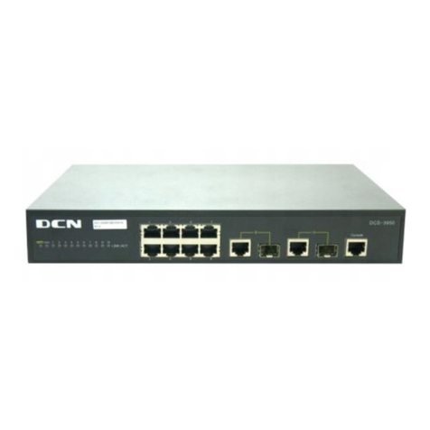
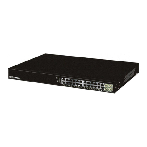
DCN DCRS-5650-28CT User manual

PortConfiguration Content
1
Content
CHAPTER 1 PORT CONFIGURATION......................................1-1
1.1 INTRODUCTION TO PORT ......................................................................1-1
1.2 NETWORK PORT CONFIGURATION TASK LIST ........................................1-1
1.3 PORT CONFIGURATION EXAMPLE .........................................................1-3
1.4 PORT TROUBLESHOOTING ...................................................................1-4
CHAPTER 2 PORT ISOLATION FUNCTION CONFIGURATION
....................................................................................................2-1
2.1 INTRODUCTION TO PORT ISOLATION FUNCTION......................................2-1
2.2 TASK SEQUENCE OF PORT ISOLATION...................................................2-1
2.3 PORT ISOLATION FUNCTION TYPICAL EXAMPLES ...................................2-2
CHAPTER 3 PORT LOOPBACK DETECTION FUNCTION
CONFIGURATION ......................................................................3-1
3.1 INTRODUCTION TO PORT LOOPBACK DETECTION FUNCTION ...................3-1
3.2 PORT LOOPBACK DETECTION FUNCTION CONFIGURATION TASK LIST .....3-2
3.3 PORT LOOPBACK DETECTION FUNCTION EXAMPLE ...............................3-3
3.4 PORT LOOPBACK DETECTION TROUBLESHOOTING ................................3-4
CHAPTER 4 ULDP FUNCTION CONFIGURATION...................4-1
4.1 INTRODUCTION TO ULDPFUNCTION.....................................................4-1
4.2 ULDP CONFIGURATION TASK SEQUENCE .............................................4-2
4.3 ULDP FUNCTION TYPICAL EXAMPLES ..................................................4-5
4.4 ULDP TROUBLESHOOTING ..................................................................4-6
CHAPTER 5 LLDP FUNCTION OPERATION CONFIGURATION

PortConfiguration Content
2
....................................................................................................5-1
5.1 INTRODUCTION TO LLDPFUNCTION .....................................................5-1
5.2 LLDPFUNCTION CONFIGURATION TASK SEQUENCE..............................5-2
5.3 LLDPFUNCTION TYPICAL EXAMPLE ....................................................5-5
5.4 LLDPFUNCTION TROUBLESHOOTING...................................................5-6
CHAPTER 6 PORT CHANNEL CONFIGURATION....................6-1
6.1 INTRODUCTION TO PORT CHANNEL.......................................................6-1
6.2 PORT CHANNEL CONFIGURATION TASK LIST .........................................6-2
6.3 PORT CHANNEL EXAMPLES .................................................................6-3
6.4 PORT CHANNEL TROUBLESHOOTING ....................................................6-5
CHAPTER 7 JUMBO CONFIGURATION...................................7-1
7.1 INTRODUCTION TO JUMBO....................................................................7-1
7.2 JUMBO CONFIGURATION TASK SEQUENCE ............................................7-1

PortConfiguration Chapter1PortConfiguration
1-1
Chapter 1 Port Configuration
1.1 Introduction to Port
DCRS-5650-28CT provides 24 fixed 100M electric ports and 4 fixed 1000M ports (2
1000M electric ports and 2 1000M combo ports).
DCRS-5650-52CT provides 48 fixed 100M electric ports and 4 fixed 1000M ports (2
1000M electric ports and 2 1000M combo ports).
DCRS-5650-28C provides 24 fixed 100M electric ports and 4 fixed 1000M combo
ports.
DCRS-5650-52C provides 48 fixed 100M electric ports and 4 fixed 1000M combo
ports.
1.2 Network Port Configuration Task List
1. Enter the network port configuration mode
2. Configure the properties for the network ports
(1) Enable/Disable ports
(2) Configure port names
(3) Configure port cable types
(4) Configure port speed and duplex mode
(5) Configure bandwidth control
(6) Configure traffic control
(7) Enable/Disable port loopback function
3. Set the date traffic suppression function
4. Virtual cable test
1. Enter the Ethernet port configuration mode
Command Explanation
Global Mode
interface ethernet <interface-list> Enters the network port configuration
mode.
2. Configure the properties for the Ethernet ports

PortConfiguration Chapter1PortConfiguration
1-2
Command Explanation
Port Mode
shutdown
no shutdown Enables/Disables specified ports.
name <string>
no name
Names or cancels the name of specified
ports.
mdi { auto | across | normal }
no mdi Sets the cable type for the specified port
speed-duplex {auto | force10-half |
force10-full | force100-half |
force100-full | force100-fx |
{{force1g-half | force1g-full}
[nonegotiate [master | slave]]}}
Sets port speed and duplex mode of 1000M
fiber ports.
bandwidth control <bandwidth>
{both | receive | transmit}
no bandwidth control
Sets or cancels the bandwidth used for
incoming/outgoing traffic for specified ports.
flow control
no flow control
Enables/Disables traffic control function for
specified ports.
loopback
no loopback
Enables/Disables loopback test function for
specified ports.
3. Set the date traffic suppression function
Command Explanation
Port Configuration Mode
rate-suppression {broadcast|
brmc|brmcdlf|all} <Kbits>
no rate-suppression
Enable the packet suppression function of
the switch, and set the allowed data traffic.
The no operation of this command will
disable this function.
4. Virtual cable test
Command Explanation
Port Configuration Mode
virtual-cable-test Test virtual cables of the port.

PortConfiguration Chapter1PortConfiguration
1-3
1.3 Port Configuration Example
Fig 1-1 Port Configuration Example
No VLAN has been configured in the switches, default VLAN1 is used.
Switch Port Property
Switch1 0/0/7 Ingress bandwidth limit: 150 M
Switch2 0/0/8 Mirror source port
0/0/9 100Mbps full, mirror source port
0/0/27 1000Mbps full, mirror destination port
Switch3 0/0/12 100Mbps full
The configurations are listed below:
Switch1:
Switch1(config)#interface ethernet 0/0/7
Switch1(Config-If-Ethernet0/0/7)#bandwidth control both 50
Switch2:
Switch2(config)#interface ethernet 0/0/9
Switch2(Config-If-Ethernet0/0/9)#speed-duplex force100-full
Switch2(Config-If-Ethernet0/0/9)#exit
Switch2(config)#interface ethernet 0/0/27
Switch2(Config-If-Ethernet0/0/27)# speed-duplex force1000-full
Switch2(Config-If-Ethernet0/0/27)#exit
Switch2(config)#monitor session 1 source interface ethernet0/0/8;0/0/9
Switch2(config)#monitor session 1 destination interface ethernet 0/0/27
Switch3:
Switch3(config)#interface ethernet 0/0/12
Switch3(Config-If-Ethernet0/0/12)#speed-duplex force1000-full
0/0/7
S
wi
tc
h 2
Switch 3
0/0/9
0/0/12 0/0/8
0/0/27
S
wi
tc
h 1

PortConfiguration Chapter1PortConfiguration
1-4
Switch3(Config-If-Ethernet0/0/12)#exit
1.4 Port Troubleshooting
Here are some situations that frequently occurs in port configuration and the advised
solutions:
&Two connected fiber interfaces won’t link up if one interface is set to auto-negotiation
but the other to forced speed/duplex. This is determined by IEEE 802.3.
&The following combinations are not recommended: enabling traffic control as well as
setting multicast limiting for the same port; setting broadcast, multicast and unknown
destination unicast control as well as port bandwidth limiting for the same port. If such
combinations are set, the port throughput may fall below the expected performance.

Port Configuration Chapter 2 Port Isolation Function Configuration
2-1
Chapter 2 Port Isolation Function
Configuration
2.1 Introduction to Port Isolation Function
Port isolation is an independent port-based function working in an inter-port way,
which isolates flows of different ports from each other. With the help of port isolation, users
can isolate ports within a VLAN to save VLAN resources and enhance network security.
After this function is configured, the ports in a port isolation group will be isolated from
each other, while ports belonging to different isolation groups or no such group can
forward data to one another normally. No more than 16 port isolation groups can a switch
have.
100M ports are usually downlink ports, and only used as uplink ones in special cases.
Please notice that 8 of them work as a whole group, which means, if ethernet 0/0/1 is
configured as an uplink port, ports from ethernet 0/0/1 to ethernet 0/0/8 will all become
uplink ones, and be able to communicate with other ports; if ethernet 0/0/1 is configured
as a downlink port, ports from ethernet 0/0/1 to ethernet 0/0/8 will all become downlink
ones. Other ports follow the same rule.
2.2 Task Sequence of Port Isolation
1. Create an isolate port group
2. Add Ethernet ports into the group
3. Display the configuration of port isolation
1. Create an isolate port group
Command Explanation
Global Mode
isolate-port group <WORD>
no isolate-port group <WORD>
Set a port isolation group; the no operation
of this command will delete the port
isolation group.
2. Add Ethernet ports into the group
Command Explanation
Global Mode

Port Configuration Chapter 2 Port Isolation Function Configuration
2-2
isolate-port group <WORD> switchport
interface [<ethernet>] <IFNAME>
no isolate-port group <WORD>
switchport interface [<ethernet>]
<IFNAME>
Add one port or a group of ports into a port
isolation group to isolate, which will become
isolated from the other ports in the group;
the no operation of this command will
remove one port or a group of ports out of a
port isolation group.
3. Display the configuration of port isolation
Command Explanation
Admin Mode and Global Mode
show isolate-port group [ <WORD> ]
Display the configuration of port isolation,
including all configured port isolation
groups and Ethernet ports in each group.
2.3 Port Isolation Function Typical Examples
Fig 2-1 A typical example of port isolation function
The topology and configuration of switches are showed in the figure above, with
e0/0/1, e0/0/10 and e0/0/17 all belonging to VLAN 100. The requirement is that, after port
e0/0
/1
S1
Vlan
e0/0/17
S3S2
e0/0
/10

Port Configuration Chapter 2 Port Isolation Function Configuration
2-3
isolation is enabled on switch S1, e0/0/1 and e0/0/10 on switch S1 can not communicate
with each other, while both of them can communicate with the uplink port e0/0/17. That is,
the communication between any pair of downlink ports is disabled while that between any
downlink port and a specified uplink port is normal. The uplink port can communicate with
any port normally.
The configuration of S1:
Switch(config)#isolate-port group test
Switch(config)#isolate-port group test switchport interface ethernet 0/0/1;0/0/10

Port Configuration Chapter 3 Port Loopback Detection
Function Configuration
3-1
Chapter 3 Port Loopback Detection
Function Configuration
3.1 Introduction to Port Loopback Detection Function
With the development of switches, more and more users begin to access the network
through Ethernet switches. In enterprise network, users access the network through
layer-2 switches, which means urgent demands for both internet and the internal layer 2
Interworking. When layer 2 Interworking is required, the messages will be forwarded
through MAC addressing the accuracy of which is the key to a correct Interworking
between users. In layer 2 switching, the messages are forwarded through MAC
addressing. Layer 2 devices learn MAC addresses via learning source MAC address, that
is, when the port receives a message from an unknown source MAC address, it will add
this MAC to the receive port, so that the following messages with a destination of this
MAC can be forwarded directly, which also means learn the MAC address once and for all
to forward messages.
When a new source MAC is already learnt by the layer 2 device, only with a different
source port, the original source port will be modified to the new one, which means to
correspond the original MAC address with the new port. As a result, if there is any
loopback existing in the link, all MAC addresses within the whole layer 2 network will be
corresponded with the port where the loopback appears (usually the MAC address will be
frequently shifted from one port to another ), causing the layer 2 network collapsed. That
is why it is a necessity to check port loopbacks in the network. When a loopback is
detected, the detecting device should send alarms to the network management system,
ensuring the network manager is able to discover, locate and solve the problem in the
network and protect users from a long-lasting disconnected network.
Since detecting loopbacks can make dynamic judgment of the existence of loopbacks
in the link and tell whether it has gone, the devices supporting port control (such as port
isolation and port MAC address learning control) can maintain that automatically, which
will not only reduce the burden of network managers but also response time, minimizing
the effect caused loopbacks to the network.

Port Configuration Chapter 3 Port Loopback Detection
Function Configuration
3-2
3.2 Port Loopback Detection Function Configuration
Task List
1.Configure the time interval of loopback detection
2.Enable the function of port loopback detection
3.Configure the control method of port loopback detection
4.Display and debug the relevant information of port loopback detection
5.Configure the loopback-detection control mode (automatic recovery enabled or
not)
1.Configure the time interval of loopback detection
Command Explanation
Global Mode
loopback-detection interval-time
<loopback> <no-loopback>
no loopback-detection interval-time
Configure the time interval of loopback
detection.
2.Enable the function of port loopback detection
Command Explanation
Port Mode
loopback-detection specified-VLAN
<vlan-list>
no loopback-detection specified-vlan
<vlan-list>
Enable and disable the function of port
loopback detection.
3.Configure the control method of port loopback detection
Command Explanation
Port Mode
loopback-detection control {shutdown
|block| learning}
no loopback-detection control
Enable and disable the function of port
loopback detection control.
4.Display and debug the relevant information of port loopback detection
Command Explanation
Admin Mode

Port Configuration Chapter 3 Port Loopback Detection
Function Configuration
3-3
debug loopback-detection
no debug loopback-detection
Enable the debug information of the
function module of port loopback
detection. The no operation of this
command will disable the debug
information.
show loopback-detection [interface
<interface-list>]
Display the state and result of the
loopback detection of all ports, if no
parameter is provided; otherwise, display
the state and result of the corresponding
ports.
5. Configure the loopback-detection control mode (automatic recovery enabled or
not)
Command Explanation
Global Mode
loopback-detection control-recovery
timeout <0-3600>
Configure the loopback-detection control
mode (automatic recovery enabled or
not) or recovery time.
3.3 Port Loopback Detection Function Example
Fig 3-1 A typical example of port loopback detection
As shown in the above configuration, the switch will detect the existence of loopbacks
in the network topology. After enabling the function of loopback detection on the port
Network Topology
SWITCH

Port Configuration Chapter 3 Port Loopback Detection
Function Configuration
3-4
connecting the switch with the outside network, the switch will notify the connected
network about the existence of a loopback, and control the port on the switch to guarantee
the normal operation of the whole network.
The configuration task sequence of SWITCH:
Switch(config)#loopback-detection interval-time 35 15
Switch(config)#interface ethernet 0/0/1
Switch(Config-If-Ethernet0/0/1)#loopback-detection special-vlan 1-3
Switch(Config-If-Ethernet0/0/1)#loopback-detection control block
3.4 Port Loopback Detection Troubleshooting
The function of port loopback detection is disabled by default and should only be
enabled if required.

Port Configuration Chapter 4 ULDP Function Configuration
4-1
Chapter 4 ULDP Function Configuration
4.1 Introduction to ULDP Function
Unidirectional link is a common error state of link in networks, especially in fiber links.
Unidirectional link means that only one port of the link can receive messages from the
other port, while the latter one can not receive messages from the former one. Since the
physical layer of the link is connected and works normal, via the checking mechanism of
the physical layer, communication problems between the devices can not be found. As
shown in Graph, the problem in fiber connection can not be found through mechanisms in
physical layer like automatic negotiation.
Fig 4-1 Fiber Cross Connection
Fig 4-2 One End of Each Fiber Not Connected
This kind of problem often appears in the following situations: GBIC (Giga Bitrate
g0/0/1
S
wi
tc
h B
Switch C
g0/0/2
g0/0/3
Switch A
g0/0/2
S
wi
tc
h B
g0/0/4
g0/0/3
g0/0/1
Switch A

Port Configuration Chapter 4 ULDP Function Configuration
4-2
Interface Converter) or interfaces have problems, software problems, hardware becomes
unavailable or operates abnormally. Unidirectional link will cause a series of problems,
such as spinning tree topological loop, broadcast black hole.
ULDP (Unidirectional Link Detection Protocol) can help avoid disasters that could
happen in the situations mentioned above. In a switch connected via fibers or copper
Ethernet line (like ultra five-kind twisted pair), ULDP can monitor the link state of physical
links. Whenever a unidirectional link is discovered, it will send warnings to users and can
disable the port automatically or manually according to users’ configuration.
The ULDP of switches recognizes remote devices and check the correctness of link
connections via interacting ULDP messages. When ULDP is enabled on a port, protocol
state machine will be started, which means different types of messages will be sent at
different states of the state machine to check the connection state of the link by
exchanging information with remote devices. ULDP can dynamically study the interval at
which the remote device sends notification messages and adjust the local TTL (time to live)
according to that interval. Besides, ULDP provides the reset mechanism, when the port is
disabled by ULDP, it can check again through reset mechanism. The time intervals of
notification messages and reset in ULDP can be configured by users, so that ULDP can
respond faster to connection errors in different network environments.
The premise of ULDP working normally is that link works in duplex mode, which
means ULDP is enabled on both ends of the link, using the same method of authentication
and password.
4.2 ULDP Configuration Task Sequence
1. Enable ULDP function globally
2. Enable ULDP function on a port
3. Configure aggressive mode globally
4. Configure aggressive mode on a port
5. Configure the method to shut down unidirectional link
6. Configure the interval of Hello messages
7. Configure the interval of Recovery
8. Reset the port shut down by ULDP
9. Display and debug the relative information of ULDP
1. Enable ULDP function globally
Command Explanation
Global configuration mode

Port Configuration Chapter 4 ULDP Function Configuration
4-3
uldp enable
uldp disable
Globally enable or disable ULDP
function.
2. Enable ULDP function on a port
Command Explanation
Port configuration mode
uldp enable
uldp disable
Enable or disable ULDP function on a
port.
3. Configure aggressive mode globally
Command Explanation
Global configuration mode
uldp aggressive-mode
no uldp aggressive-mode Set the global working mode.
4. Configure aggressive mode on a port
Command Explanation
Port configuration mode
uldp aggressive-mode
no uldp aggressive-mode Set the working mode of the port.
5. Configure the method to shut down unidirectional link
Command Explanation
Global configuration mode
uldp manual-shutdown
no uldp manual-shutdown
Configure the method to shut down
unidirectional link.
6. Configure the interval of Hello messages
Command Explanation
Global configuration mode
uldp hello-interval <integer>
no uldp hello-interval
Configure the interval of Hello messages,
ranging from 5 to 100 seconds. The
value is 10 seconds by default.
7. Configure the interval of Recovery
Command Explanation
Global configuration mode

Port Configuration Chapter 4 ULDP Function Configuration
4-4
uldp recovery-time <integer>
no uldp recovery-time <integer>
Configure the interval of Recovery reset,
ranging from 30 to 86400 seconds. The
value is 0 second by default.
8. Reset the port shut down by ULDP
Command Explanation
Global configuration mode or port
configuration mode
uldp reset
Reset all ports in global configuration
mode;
Rest the specified port in
port configuration mode.
9. Display and debug the relative information of ULDP
Command Explanation
Admin mode
show uldp [interface ethernet IFNAME]
Display ULDP information. No parameter
means to display global ULDP
information. The parameter specifying a
port will display global information and
the neighbor information of the port.
debug uldp fsm interface ethernet
<IFname>
no debug uldp fsm interface ethernet
<IFname>
Enable or disable the debug switch of the
state machine transition information on
the specified port.
debug uldp error
no debug uldp error
Enable or disable the debug switch of
error information.
debug uldp event
no debug uldp event
Enable or disable the debug switch of
event information.
debug uldp packet {receive|send}
no debug uldp packet {receive|send}
Enable or disable the type of messages
can be received and sent on all ports.
debug uldp {hello|probe|echo|
unidir|all}[receive|send] interface
ethernet <IFname>
no debug uldp {hello|probe|echo|
unidir|all}[receive|send] interface
ethernet <IFname>
Enable or disable the content detail of a
particular type of messages can be
received and sent on the specified port.

Port Configuration Chapter 4 ULDP Function Configuration
4-5
4.3 ULDP Function Typical Examples
Fig 4-3 Fiber Cross Connection
In the network topology in Graph, port g0/0/1 and port g0/0/2 of SWITCHA as well as
port g0/0/3 and port g0/0/4 of SWITCH B are all fiber ports. And the connection is cross
connection. The physical layer is connected and works normally, but the data link layer is
abnormal. ULDP can discover and disable this kind of error state of link. The final result is
that port g0/0/1, g0/0/2 of SWITCH A and port g0/0/3, g0/0/4 of SWITCH B are all shut
down by ULDP. Only when the connection is correct, can the ports work normally (won’t
be shut down).
Switch A configuration sequence:
SwitchA(config)#uldp enable
SwitchA(config)#interface ethernet 0/0/1
SwitchA (Config-If-Ethernet0/0/1)#uldp enable
SwitchA (Config-If-Ethernet0/0/1)#exit
SwitchA(config)#interface ethernet0/0/2
SwitchA(Config-If-Ethernet0/0/2)#uldp enable
Switch B configuration sequence:
SwitchB(config)#uldp enable
SwitchB(config)#interface ethernet0/0/3
SwitchB(Config-If-Ethernet0/0/3)#uldp enable
SwitchB(Config-If-Ethernet0/0/3)#exit
SwitchB(config)#interface ethernet0/0/4
SwitchB(Config-If-Ethernet0/0/4)#uldp enable
As a result, port g0/0/1, g0/0/2 of SWITCH A are all shut down by ULDP, and there is
g0/0/2
S
wi
tc
h B
g0/0/4
g0/0/3
g0/0/1
Switch A
PC1 PC2

Port Configuration Chapter 4 ULDP Function Configuration
4-6
notification information on the CRT terminal of PC1.
%Oct 29 11:09:50 2007 A unidirectional link is detected! Port Ethernet0/0/1 need to
be shutted down!
%Oct 29 11:09:50 2007 Unidirectional port Ethernet0/0/1 shut down!
%Oct 29 11:09:50 2007 A unidirectional link is detected! Port Ethernet0/0/2 need to
be shutted down!
%Oct 29 11:09:50 2007 Unidirectional port Ethernet0/0/2 shutted down!
Port g0/0/3, and port g0/0/4 of SWITCH B are all shut down by ULDP, and there is
notification information on the CRT terminal of PC2.
%Oct 29 11:09:50 2007 A unidirectional link is detected! Port Ethernet0/0/3 need to
be shutted down!
%Oct 29 11:09:50 2007 Unidirectional port Ethernet0/0/3 shutted down!
%Oct 29 11:09:50 2007 A unidirectional link is detected! Port Ethernet0/0/4 need to
be shutted down!
%Oct 29 11:09:50 2007 Unidirectional port Ethernet0/0/4 shutted down!
4.4 ULDP Troubleshooting
Configuration Notice:
&In order to ensure that ULDP can discover that the one of fiber ports has not
connected or the ports are incorrectly cross connected, the ports have to work in
duplex mode and have the same rate.
&If the automatic negotiation mechanism of the fiber ports with one port misconnected
decides the working mode and rate of the ports, ULDP won’t take effect no matter
enabled or not. In such situation, the port is considered as “Down”.
&In order to make sure that neighbors can be correctly created and unidirectional links
can be correctly discovered, it is required that both end of the link should enable
ULDP, using the same authentication method and password.At present, no password
is needed on both ends.
&The hello interval of sending hello messages can be changed (it is10 seconds by
default and ranges from 5 to 100 seconds) so that ULDP can respond faster to
connection errors of links in different network environments. But this interval should
be less than 1/3 of the STP convergence time. If the interval is too long, a STP loop
will be generated before ULDP discovers and shuts down the unidirectional
connection port. If the interval is too short, the network burden on the port will be
increased, which means a reduced bandwidth.
&ULDP does not handle any LACP event. It treats every link of TRUNK group (like
Port-channal, TRUNK ports) as independent, and handles each of them respectively.

Port Configuration Chapter 4 ULDP Function Configuration
4-7
&ULDP does not compact with similar protocols of other vendors, which means users
can not use ULDP on one end and use other similar protocols on the other end.
&ULDP function is disabled by default. After globally enabling ULDP function, the
debug switch can be enabled simultaneously to check the debug information. There
are several DEBUG commands provided to print debug information, such as
information of events, state machine, errors and messages. Different types of
message information can also be printed according to different parameters.
&The Recovery timer is disabled by default and will only be enabled when the users
have configured recovery time (30-86400 seconds).
&Reset command and reset mechanism can only reset the ports automatically shut
down by ULDP. The ports shut down manually by users or by other modules won’t be
reset by ULDP.
This manual suits for next models
3
Table of contents
Other DCN Network Router manuals
