DCS ATrack AK11 User manual

Presents:
AK11
User Manual
Revision: V05
Revision Date: 2018/05/08
Direct Communications Solutions Inc.
17150 Via del Campo Suite #200
San Diego, CA 92127
Tel: 858-798-7100
Fax: 858-408-3045
www.dcsbusiness.com

Confidential Document
Page 2 of 27
Table of Contents
1.
Notification..........................................................................................................................3
1.1.
Disclaimer ............................................................................................................................... 3
1.2.
Copyright ................................................................................................................................ 3
1.3.
Warning .................................................................................................................................. 3
2.
Introduction ........................................................................................................................4
3.
Installation ..........................................................................................................................5
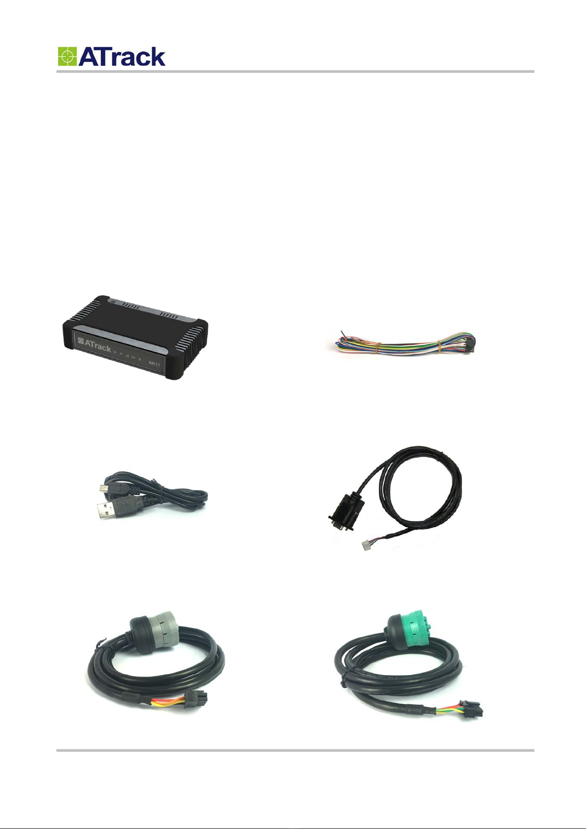
3.1.
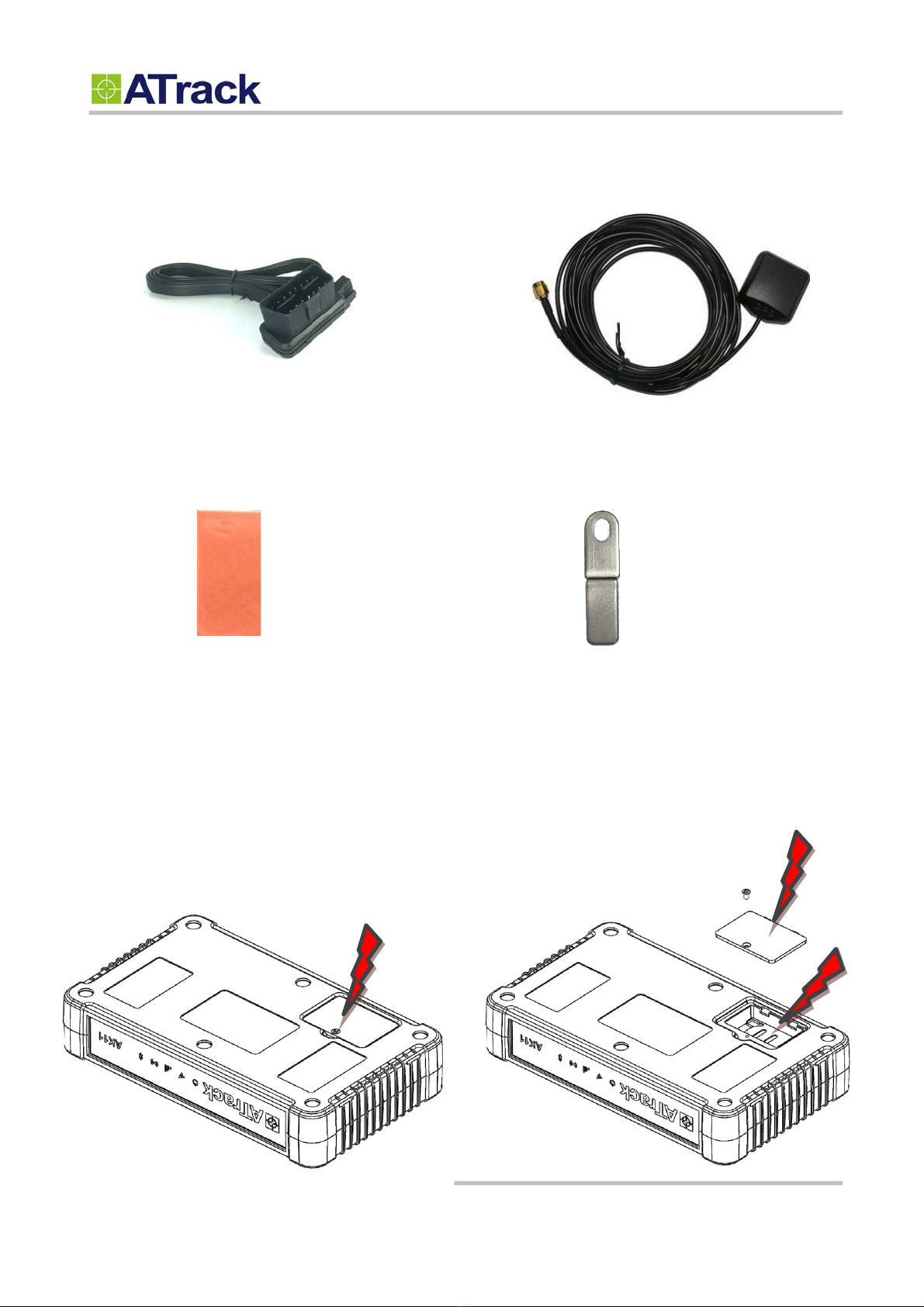
Package Content .................................................................................................................... 5
3.2.
SIM Card Installation ............................................................................................................... 6
3.3.
Power I/O Pin Assignment....................................................................................................... 7
3.4.
AT$IOCG Configure I/O Pin Characteristics .......................................................................... 8
3.5.
DLC Pin Assignment ............................................................................................................... 9
3.6.
USB Port and Driver Installation ............................................................................................ 10
3.7.
LED Indicators ...................................................................................................................... 11
4.
Bluetooth (Optional).........................................................................................................12
4.1.
AT$BTEN Query or set the Bluetooth connection property .................................................. 12
4.2.
Demo APP ............................................................................................................................ 14
4.3.
SDK for Android and iOS APP ............................................................................................... 16
5.
WiFi HotSpot (Optional) ..................................................................................................17
5.1.
AT$WIFI Query or set the WiFi hotspot property ................................................................. 17
5.2.
AT$IPFC Query or set the IP Filter property ........................................................................ 18
5.3.
AT$MDSC Query or set the Data Usage Monitoring property .............................................. 19
6.
Configuration....................................................................................................................20
6.1.
Connecting a Device Using HyperTerminal ........................................................................... 20
6.2.
Connecting AK11 to a Remote Server ................................................................................... 23
7.
Firmware Upgrade ...........................................................................................................24
8.
Cellular Selecting..............................................................................................................26
8.1.
AT$FUNC="USEN" Query or set the US Cellular ................................................................ 26
9.
Double Side Tape....................................................................................................................... 27
10.
Mounting Bracket.............................................................................................................27

Confidential Document
Page 3 of 27
1
1.
.
N
No
ot
ti
if
fi
ic
ca
at
ti
io
on
n
1
1.
.1
1.
.
D
Di
is
sc
cl
la
ai
im
me
er
r
This document, and all other related products, including device, firmware, and software, are exclusively
developed by ATrack Technology Inc. Due to the continuous developments and improvements of device
functionalities, changes in the protocol, specification, and firmware functions are subjects to change without
notice. ATrack Technology Inc. reserves the right to modify all documentations based on its own timelines.
Document modification notices will be released to ATrack Technology Inc.’s customers upon completion.
ATrack Technology Inc. products are not intended to be used as life support or rescue equipment. ATrack
Technology Inc. is not liable for any loss or injury caused by using or referencing to any of its products. Any
possible means of using or integrating ATrack Technology Inc. products shall be avoided.
1
1.
.2
2.
.
C
Co
op
py
yr
ri
ig
gh
ht
t
ATrack Technology Inc. holds all parts of intellectual rights applicable in the copyright laws in all the countries.
Any and all contents of this document shall not be exposed, delivered, and/or disclosed to non-authorized 3rd
party without any form of approval and consent from ATrack Technology Inc. Any form of, including but not
limited to, verbal, duplicate, or internet sharing, of releasing or exposing information to an unauthorized party
shall be prohibited. ATrack Technology Inc. reserves the rights of litigation in the violation of copyright laws.
1
1.
.3
3.
.
W
Wa
ar
rn
ni
in
ng
g
Connecting of the input wires can be hazardous to both the installer and your vehicle’s electrical system if not
done by an inexperienced installer. This document assumes you are aware of the inherent dangers of working
in and around a vehicle and have qualified understanding of electrical behaviors.

Confidential Document
Page 4 of 27
2
2.
.
I
In
nt
tr
ro
od
du
uc
ct
ti
io
on
n
Congratulations on your purchase of the ATrack AK11 Vehicle Telematics device. The AK11 is equipped with
state of the art cellular and GPS technology, providing the most reliable and up-to-date information of your
vehicle’s location and movement status. In addition, vehicle tracking can be combined with a variety of
customized events based on your needs.

Confidential Document
Page 5 of 27
*AK11 Device * 1
3
3.
.
I
In
ns
st
ta
al
ll
la
at
ti
io
on
n
3
3.
.1
1.
.
P
Pa
ac
ck
ka
ag
ge
e
C
Co
on
nt
te
en
nt
t
When you open the package, verify that you received the following:
* I/O Cable * 1
*USB Cable * 1 (Optional) * Serial Cable * 1 (Optional)
*
J1708 Cable * 1 (Optional) * J1939 Cable * 1 (Optional)

Confidential Document
Page 6 of 27
*
OBD Cable * 1 (Optional) * GPS external antenna * 1 (Optional)
*
Double Side Tape * 2 * Mounting Bracket * 4 (Optional)
3
3.
.2
2.
.
S
SI
IM
M
C
Ca
ar
rd
d
I
In
ns
st
ta
al
ll
la
at
ti
io
on
n
AK11 supports SIM cards with 1.8V (ISO/IEC 7816-3 class C) or 3V (ISO/IEC 7816-3 class B) operating
voltages. To install a SIM card, remove the screw and the cover.

Confidential Document
Page 7 of 27
3
3.
.3
3.
.
P
Po
ow
we
er
r
I
I/
/O
O
P
Pi
in
n
A
As
ss
si
ig
gn
nm
me
en
nt
t
Pin1
Yellow
Pin3
Purple
Pin5
Pink
Pin7
White
Pin9
Dark Brown
Pin11
Light Blue
Pin13
Red
Pin2
Dark Green
Pin4
Blue
Pin6
Light Brown
Pin8
Orange
Pin10
Gray
Pin12
Green
Pin14
Black
The following table describes the function of each bare wire.
Power I/O Connector
Pin#
Function
Color
Designation
Note
1
ACC Input
Yellow
ACC
Ignition status positive trigger input
2
General Input1
Dark Green
IN1
Positive trigger input
3
General Input2
Purple
IN2
Negative trigger input
4
General Input3
Blue
IN3
Negative trigger input
5**
General Input4 (Default)
General Output5
Analog Input1
Pink
IN4/O5/A1
Positive trigger input
Open collector output (Max.300mA)
Analog input (DC0V~40V)
6
General Input5
Light Brown
IN5
Negative trigger input
7**
General Input6
General Output1 (Default)
White
IN6/O1
Negative trigger input
Open collector output (Max.300mA)
8**
General Input7
General Output2 (Default)
Analog Input2
Orange
IN7/O2/A2
Positive trigger input
Open collector output (Max.300mA)
Analog input (DC0V~40V)
9
General Output3
Dark Brown
O3
Open collector output (Max.300mA)
10**
General Input8
General Output4 (Default)
White
IN8/O4
Negative trigger input
Open collector output (Max.300mA)
11
Analog Input3
Light Blue
A3
Analog input (DC0V~5V)
12
1-Wire Protocol Input
Green
1W
1-Wire Data Input
13
Main power input
Red
PWR
DC 8V~40V DC input
14
Common ground
Black
GNT
Ground

Confidential Document
Page 8 of 27
* 1-Wire® Protocol supports up to three 1-Wire™ devices simultaneously, which means you can have one
iButton® sensor (DS1990A) and two 1-Wire™ temperature sensor probes (DS18B20).
** You may configure the AT$IOCG command to change these specific I/O pins to any of those functions
mentioned as above. Note: Please do not connect a positive voltage to any output pin!
3
3.
.4
4.
.
A
AT
T$
$I
IO
OC
CG
G
C
Co
on
nf
fi
ig
gu
ur
re
e
I
I/
/O
O
P
Pi
in
n
C
Ch
ha
ar
ra
ac
ct
te
er
ri
is
st
ti
ic
cs
s
Command Description
This command is used to set or query the I/O port characteristics of the AK11. It is recommended to disconnect all I/O
connections prior to changing the I/O characteristic in order to avoid damage to the I/O port.
Syntax
Write Command
AT$IOCG=<IO1>,<IO2>,<IO3>,<IO4>
Response
$OK
Read Command
AT$IOCG=?
Response
$IOCG=<IO1>,<IO2>,<IO3>,<IO4>
Parameter Description
Parameters
Description
Data Type
Default
<IO1>
1: Input 4
2: Output 5
3: Analog Input 1
U8
1
<IO2>
1: Input 7
2: Output 2
3: Analog Input 2
U8
2
<IO3>
1: Input 6
2: Output 1
U8
2
<IO4>
1: Input 8
2: Output 4
U8
2
Example
(1)
Change all ports to inputs:
AT$IOCG=1,1,1,1
(2)
Change IO1, IO3 and IO4 to inputs, and IO2 to analog input:
AT$IOCG=1,3,1,1
Remark
MEMO
SERIAL
SMS
GPRS

Confidential Document
Page 9 of 27
3
3.
.5
5.
.
D
DL
LC
C
P
Pi
in
n
A
As
ss
si
ig
gn
nm
me
en
nt
t
Pin1
Pin3
Pin5
Pin7
Pin9
Pin11
Pin2
Pin4
Pin6
Pin8
Pin10
Pin12
The following table describes the function of each pin.
Power I/O Connector
Pin#
Function
Color
Designation
Note
1
Main power input
DC 8V~40V DC input
2
Power ground
Ground
3
J1850BUS+
4
J1850BUS-
5
K-line
6
7
RS485_A+/ J1708+
8
RS485_B-/ J1708-
9
CAN HI/ J1939+
10
CAN Lo/ J1939-
11
12

Confidential Document
Page 10 of 27
3
3.
.6
6.
.
U
US
SB
B
P
Po
or
rt
t
a
an
nd
d
D
Dr
ri
iv
ve
er
r
I
In
ns
st
ta
al
ll
la
at
ti
io
on
n
The following figure shows the position of AK11’s USB port.
USB Port
Double click the USB driver VCP_V1.3.1_Setup/ VCP_V1.3.1_Setup_x64. Then, click the Finish button to
complete the process.
Note: Please connect the main power to AK11 in order for the USB to work properly.

Confidential Document
Page 11 of 27
3
3.
.7
7.
.
L
LE
ED
D
I
In
nd
di
ic
ca
at
to
or
rs
s
The following figure shows the location of AK11’s LEDs.
LED
Indication
Description
PWR (Green)
Solid On
In full operation mode
1 blink (0.1 sec.) in every 8 sec.
In sleep mode
GPS (Red)
0.7 sec. On, 0.7 sec. Off
Searching for GPS signal
Solid On
Position fixed
WWAN (Red)
Off
WWAN module off
0.7 sec. On, 0.7 sec. Off
Searching for WWAN signal
0.2 sec. On, 2 sec. Off
Registered to WWAN network
2 blinks in every 2 sec.
Connected to WWAN network
Continuous blinking
SIM PIN Error
WIFI Hotspot (Red)
Bluetooth
Solid On
If a BT gadget is connected
Off
No BT gadget is connected
Note: In the case of SIM PIN Error, the device will check the AT$SPIN every 10 minutes and try to
access the SIM again. The PIN will be validated 3 times and if it fails the 3rd attempt, including the first
inserting time, the SIM card will be locked. Once the SIM is locked, you need to contact your GSM
carrier for the PUK in order to unlock the SIM card using your cell phone.
PWR
GPS
WWAN
WIFI
Bluetooth

Confidential Document
Page 12 of 27
4
4.
.
B
Bl
lu
ue
et
to
oo
ot
th
h
(
(O
Op
pt
ti
io
on
na
al
l)
)
4
4.
.1
1.
.
A
AT
T$
$B
BT
TE
EN
N
Q
Qu
ue
er
ry
y
o
or
r
s
se
et
t
t
th
he
e
B
Bl
lu
ue
et
to
oo
ot
th
h
c
co
on
nn
ne
ec
ct
ti
io
on
n
p
pr
ro
op
pe
er
rt
ty
y
Command Description
This command is used to set Bluetooth Low Energy (single mode) configuration.
Syntax
Write Command
AT$BTEN=<Mode>,<"Password">,<"Name">,<Position Format>,<Format Filter>,<"Custom
Info">,<"JData Fields">,<ZData Fields>.<Timeout>,<Retry>,<ReportACK>
Response
$OK
Read Command
AT$BTEN=?
Response
$BTEN=<BT Mode>,<"Password">,<"Name">,<Position Format>,<Format Filter>,<"Custom
Info">,<"JData Fields">,<Timeout>,<Retry>,<ReportACK>
Parameter Description
Parameters
Description
Data Type
Default
<Mode>
Setup BT reporting mode
0: Follow AT$TRAC setting
1 ~ 255: Reporting Interval in seconds
U8
0
<"Password">
Setting for BT connection password. This password is
needed for establish the BT connection.
String(4)
""
<"Name">
Setting for BT names when searching for device.
String(10)
""
<Position Format>
To setup report format.
0: ASCII
1: Binary
U8
0
<Format Filter>
To setup if ATrack standard format or custom format should
be used to construct the report. If custom format is set, the
device will send the report in the order of
<Header><"Custom Info"><"JData Fields"><"ZData
Fields">
0: ATrack standard format
1: Custom format
U8
0
<"Custom Info">
To append or setup custom report format. If <Format Filter>
is set to 0, variables specified in this field will be appended
to the ATrack standard format string. Refer to ATrack AK11
String(100)
""

Confidential Document
Page 13 of 27
Protocol Document AT$FORM command pages for
available % variables.
<"JData Fields">
To append or setup custom report format. If <Format Filter>
is set to 0, variables specified in this field will be appended
to the ATrack standard format string. Refer to ATrack AK11
Protocol Document AT$FMSC command pages for
available % variables.
String(100)
""
<"ZData Fields">
To append or setup custom report format. If <Format Filter>
is set to 0, variables specified in this field will be appended
to the ATrack standard format string. Refer to ATrack AK11
Protocol Document AT$1708 command pages for available
% variables.
String(100)
""
<Timeout>
Timeout in seconds for each data transmission retries.
U8
10
<Retry>
Number of data sending retries in case of transmission
failure.
U8
3
<ReportACK>
Specify if an Acknowledge is required or not. If the ACK is
required, device will wait for the ACK and then send out
next report. If no ACK is received within <TimeOut> value
for <Retry> + 1 times, the device will reset BT module. The
external BT device should try to connect again in such
case. Reports not acknowledged will be queued and wait
for next connection.
0: ACK not required
1: ACK required
U8
0
Example
Setup reporting interval as AT$TRAC, connection password "1234", and Device name as "future":
AT$BTEN=0,"1234","future"
Setup reporting interval to 5 seconds, no connection password, device name as "AK11BT", and enable report ack:
AT$BTEN=5,"","AK11BT",,,,,,,1
Setup binary format data, reporting interval to 3 seconds, no connection password, device name as "AK11GW", and adding
multiple % variables for OBDII data:
AT$BTEN=3,"","AK11GW",1,,"%RP%SD%TR%EL%ET%FC%VN%MF%MP%IA"
Setup custom format with above 3rd condition and J1939 data:
AT$BTEN=3,"","AK11GW",1,1,"%RP%SD%TR%EL%ET%FC%VN%MF%MP%IA","%JO1%JO2%JO3%JO4"
Remark
MEMO SERIAL SMS GPRS

Confidential Document
Page 14 of 27
4
4.
.2
2.
.
D
De
em
mo
o
A
AP
PP
P
Please download “Terminal IO” from either Apple Store or Google Play. And you can see the screen below
when you open the APP.
Press the “Scan” button to scan AK11. The default name “AK11_last_5_digits of IMEI” should be found and
shown in the list. And, press the “Connect” button to get the connection established.

Confidential Document
Page 15 of 27
After the Connect button is pressed, the connecting process will be executed immediately. And, the message
box of Bluetooth Pairing Request should be popped up in short. The default password is “000000”
The icon at the bottom can be seen if the connecting process is successfully finished. Please press the icon to
jump into next page.

Confidential Document
Page 16 of 27
With the properly configuration, the position report can be obtained by the APP via Bluetooth.
4
4.
.3
3.
.
S
SD
DK
K
f
fo
or
r
A
An
nd
dr
ro
oi
id
d
a
an
nd
d
i
iO
OS
S
A
AP
PP
P
Please contact your technical consultant at ATrack for the SDK document.

Confidential Document
Page 17 of 27
5
5.
.
W
Wi
iF
Fi
i
H
Ho
ot
tS
Sp
po
ot
t
(
(O
Op
pt
ti
io
on
na
al
l)
)
5
5.
.1
1.
.
A
AT
T$
$W
WI
IF
FI
I
Q
Qu
ue
er
ry
y
o
or
r
s
se
et
t
t
th
he
e
W
Wi
iF
Fi
i
h
ho
ot
ts
sp
po
ot
t
p
pr
ro
op
pe
er
rt
ty
y
Command Description
This command is used to set or query WiFi hotspot property
Syntax
Write Command
AT$WIFI=<Enable>,<"SSID">,<Encryption Type>,<"Encryption Key">,<Clients>
Response
$OK
Read Command
AT$WIFI=?
Response
$WIFI=<Enable>,<SSID>,<Encryption Type>,<"Encryption Key">,<Clients>,<"Mac address">
Parameter Description
Parameters
Description
Data Type
Default
<Enable>
0: Disable
1: Enable
U8
0
<SSID>
Set the SSID of the WIFI access point with which the
clients connect to.
String(32)
"ATRACK_WIFI"
<Encryption Type>
0
– Open
1
– WEP
2
– WPA & WPA2 (factory default)
2
<"Encryption Key">
Set key of the WEP encryption
WPA: 8 to 63 characters
WEP: 5 to 13 characters
String(64)
"password"
<Clients>
Set the maximum clients can be connected to this
WiFi hot spot. (1~4 clients)
U8
1
<Mac address>
The Mac address
"XX:XX:XX:XX:XX:XX"
Example
Enable the WiFi hotspot function with displaying name of ATrack_AK11 and password of 19850428
AT$WiFi=1,"ATrack_AK11",,"19850428"
Remark
MEMO
SERIAL
SMS
GPRS

Confidential Document
Page 18 of 27
5
5.
.2
2.
.
A
AT
T$
$I
IP
PF
FC
C
Q
Qu
ue
er
ry
y
o
or
r
s
se
et
t
t
th
he
e
I
IP
P
F
Fi
il
lt
te
er
r
p
pr
ro
op
pe
er
rt
ty
y
Command Description
This command is used to set or query IP filter property
Syntax
Write Command
AT$IPFC=<Enable>,<"IP Address1">,<"IP Address2"> …<"IP Address28">
Response
$OK
Read Command
AT$IPFC=?
Response
$IPFC=<Enable>,<"IP Address1">,<"IP Address2"> …<"IP Address28">
Parameter Description
Parameters
Description
Data Type
Default
<Enable>
0: Disable
1: Enable Black list
2: Enable While list
U8
0
<IP Address#>
Set the IPV4 IP address.
String(16)
""
Example
Enable the Black list with “61.219.81.246”, “58.214.36.33”,”219.88.56.98”,”43.48.33.244”
AT$IPFC=1,"61.219.81.246","58.214.36.33","219.88.56.98","43.48.33.244"
Enable the While list with “61.19.81.246”, “58.214.36.33”,”219.88.56.98”,”43.48.33.44”
AT$IPFC=2,"61.19.81.246","58.214.36.33","219.88.56.98","43.48.33.44"
NOTE:
The IP on the Black list is the IP not being allowed to be accessed.
The IP on the While list is the IP only being allowed to be accessed.
Remark
MEMO
SERIAL
SMS
GPRS

Confidential Document
Page 19 of 27
5
5.
.3
3.
.
A
AT
T$
$M
MD
DS
SC
C
Q
Qu
ue
er
ry
y
o
or
r
s
se
et
t
t
th
he
e
D
Da
at
ta
a
U
Us
sa
ag
ge
e
M
Mo
on
ni
it
to
or
ri
in
ng
g
p
pr
ro
op
pe
er
rt
ty
y
Command Description
This command is used to set or query the Data Usage Monitoring property
Syntax
Write Command
AT$MDSC= <Time>,<Maximum Usage>,<Maximum Usage of Upload>,<Maximum Usage of
Download>
Response
$OK
Read Command
AT$MDSC=?
Response
$MDSC= <Reset Time>,<Maximum Usage>,<Maximum Usage of Upload>,<Maximum Usage
of Download>,<Current Usage of Upload>,<Current Usage of Download>
Parameter Description
Parameters
Description
Data Type
Default
<Time>
Days need to be elapsed before reset the current
usage status (Min. 1 day)
U8
0
<Maximum Usage>
The total amount of Mb it can take to upload and
download.(Min. 0.1Mb)
U64
0
<Maximum Usage of
Upload>
The total amount of Mb it can take to upload
(Min. 0.1Mb).
U64
0
<Maximum Usage of
Download>
The total amount of Mb it can take to download
(Min. 0.1Mb)
U64
0
<Current Usage of
Upload>
The total amount of Mb it has taken to upload since
last reset
U64
0
<Current Usage of
Download>
The total amount of Mb it has taken to download
since last reset
U64
0
Example
To reset the counter of data usage every 30 days, and 10Mb for maximum usage that 6Mb for uploading and 4Mb for
downloading.
AT$MDSC=30,100,60,40
NOTE:
1.
The Upload will be locked when the usage is over the threshold you set on Maximum Usage of Upload. However, the
tracking data transmission will not be affected.
2.
The Download will be locked when the usage is over the threshold you set on Maximum Usage of Download.
However, the tracking data transmission will not be affected.
Remark
MEMO
SERIAL
SMS
GPRS

Confidential Document
Page 20 of 27
6
6.
.
C
Co
on
nf
fi
ig
gu
ur
ra
at
ti
io
on
n
You can explore many of AK11’s great features through AT commands. The commands can be sent to AK11
via USB, SMS or cellular network (e.g. WCDMA/ LTE).
6
6.
.1
1.
.
C
Co
on
nn
ne
ec
ct
ti
in
ng
g
a
a
D
De
ev
vi
ic
ce
e
U
Us
si
in
ng
g
H
Hy
yp
pe
er
rT
Te
er
rm
mi
in
na
al
l
The following example shows how to connect the AK11 through Hyper Terminal. You may use other popular
terminal emulators such as Putty or Tera Term Pro to establish a console session with the AK11.
(1)
Run HyperTerminal and select the correct COM port and click on the [Configure…] button.
Table of contents