CORTO-C INSTALLATION GUIDE |PAGE
INSTALLATION INSTRUCTIONS
PRE WIRING – CONTINUED
• For masonry walls using an angle grinder and masonry cutting disc, cut a 25mm deep slot from the cable leg to the eventual location
of the transformer, see Fig 2.0.
• Place the supplied low voltage wiring in the slot created and render over directly.
• Black polytube is supplied to locate the wire in the correct position. Conduit may also be used but is not essential.
• Low voltage wiring tails should protrude from the nished lined wall approx 150mm to allow for trimming.
3. TOWEL RAIL ASSEMBLY
• Fix the legs to the towel rail using the stainless steel machine screws and spring washers supplied. See Fig 3.0
• The small grub screw holes must face, what will be, the BOTTOM of the towel rail.
4. TOWEL RAIL FIXING / CONNECTION
• If a wirenut is accidentally removed, it may be reconnected with the spare waterproof wirenut connector provided. Waterproof wirenuts
MUST NOT BE REUSED.
• Fix the round polycarbonate bushes to the wall using the screws provided. DO NOT substitute other screws. In particular, DO NOT
use countersunk head screws less than 50mm long.
• Use the towel rail as a guide to determine the correct position for the bushes. MAKE SURE IT IS LEVEL.
• Make the electrical connection to the towel rail using the waterproof wirenut connectors provided. See Fig 7.0
• The connectors and excess wiring should be pushed back into the leg of the towel rail and/or into the wall.
• If there is a concern that water may enter into the wall cavity, neutral cure silicone sealant may be applied around the cable where it
exits the wall lining.
• Finally, x the towel rail in position using the self tapping grub screws provided. See Fig 5.0
5. TIMER AND SWITCH
• The towel rail must have a switch in the bathroom that can be identied as the towel rail switch. This is typically a separate switch
mechanism on the light switch plate for the bathroom. eg. 3 gang switch plate – lights – extractor – towel rail.
• The supplied ‘ECOTIMER’ is a 230 – 240V device that should be installed behind the switchplate between the switch and the transformer.
See Fig 6.0.
FIGURE 4 FIGURE 5 FIGURE 6
ELECTRICIANS please ensure a copy of the installation
instructions is left with the end user for future reference.
DCS
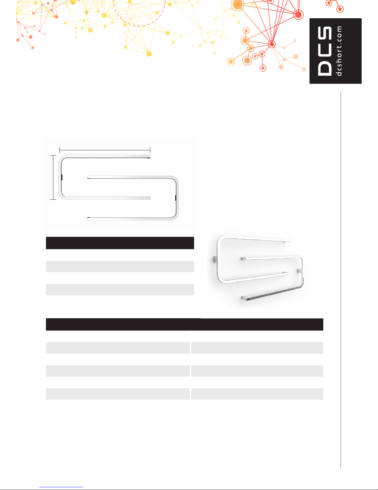
CORTO 350, 550, 750
Electricians, please ensure a copy of the installation
instructions is left with the end user for future reference
2. PRE WIRING - CONTINUED.
• For masonry walls using an angle grinder and masonry cutting disc,
cut a 25mm deep slot from the cable leg to the eventual location of the
transformer, see Fig 2.0
• Place the supplied low voltage wiring in the slot created and render over
directly.
• Black poly tube is supplied to locate the wire in the correct position. Conduit
may also be used but is not essential.
• Low voltage wiring tails should protrude from the nished lined wall approx
150mm to allow for trimming.
3. TOWEL RAIL ASSEMBLY
• Fix the legs to the towel rail using the stainless steel machine screws and
spring washer supplied. See Fig 3.0
• The small grub screw holes must face, what will be, the BOTTOM of the
towel rail.
3. TOWEL RAIL CONNECTION
• Fix the polycarbonate rectangular bushes to the wall using the screws
provided. DO NOT substitute other screws. In particular, DO NOT use
countersunk head screws less than 50mm long. See Fig 4.0
• Use the towel rail as a guide to determine the correct position for the bushes
or use the xing dimensions Table 1.0. MAKE SURE IT IS LEVEL.
• Make the electrical connection to the towel rail using the waterproof wirenut
connectors provided. See Fig 7.0
Waterproof wirenuts MUST NOT BE REUSED. A spare is included.
• The connectors and excess wiring should be pushed back into the leg of
the towel rail.
• If there is a concern that water may enter into the wall cavity, neutral cure
silicone sealant may be applied around the cable where it exits the wall
lining.
• Finally, x the towel rail in position using the small stainless steel screws
provided. See Fig 5.0
• Note: Drilling a 2mm pilot hole makes it much easier to screw in the
self tapping screws. The bushes are moulded from glass reinforced
polycarbonate and are very hard.
5. TIMER AND SWITCH
• The towel rail must have a switch in the bathroom that can be identied
as the towel rail switch. This is typically a separate switch mechanism on
the light switch plate for the bathroom. eg. 3 gang switch plate - lights -
extractor - towel rail
• The supplied ‘ECOTIMER’ is a 230 - 240V device that should be installed
behind the switchplate between the switch and the transformer. See Fig 6.0
To wel Rail
Wall Switch
Transformer
N
L
Mains
12 Volt
Ecotimer
Red
Blue
Brown
To wel Rail
To wel Rail
Screw xing approx 14mm
from cable hole centre
10mm
hole
DCS
CORTO 350, 550, 750
Electricians, please ensure a copy of the installation
instructions is left with the end user for future reference
2. PRE WIRING - CONTINUED.
• For masonry walls using an angle grinder and masonry cutting disc,
cut a 25mm deep slot from the cable leg to the eventual location of the
transformer, see Fig 2.0
• Place the supplied low voltage wiring in the slot created and render over
directly.
• Black poly tube is supplied to locate the wire in the correct position. Conduit
may also be used but is not essential.
• Low voltage wiring tails should protrude from the nished lined wall approx
150mm to allow for trimming.
3. TOWEL RAIL ASSEMBLY
• Fix the legs to the towel rail using the stainless steel machine screws and
spring washer supplied. See Fig 3.0
• The small grub screw holes must face, what will be, the BOTTOM of the
towel rail.
3. TOWEL RAIL CONNECTION
• Fix the polycarbonate rectangular bushes to the wall using the screws
provided. DO NOT substitute other screws. In particular, DO NOT use
countersunk head screws less than 50mm long. See Fig 4.0
• Use the towel rail as a guide to determine the correct position for the bushes
or use the xing dimensions Table 1.0. MAKE SURE IT IS LEVEL.
• Make the electrical connection to the towel rail using the waterproof wirenut
connectors provided. See Fig 7.0
Waterproof wirenuts MUST NOT BE REUSED. A spare is included.
• The connectors and excess wiring should be pushed back into the leg of
the towel rail.
• If there is a concern that water may enter into the wall cavity, neutral cure
silicone sealant may be applied around the cable where it exits the wall
lining.
• Finally, x the towel rail in position using the small stainless steel screws
provided. See Fig 5.0
• Note: Drilling a 2mm pilot hole makes it much easier to screw in the
self tapping screws. The bushes are moulded from glass reinforced
polycarbonate and are very hard.
5. TIMER AND SWITCH
• The towel rail must have a switch in the bathroom that can be identied
as the towel rail switch. This is typically a separate switch mechanism on
the light switch plate for the bathroom. eg. 3 gang switch plate - lights -
extractor - towel rail
• The supplied ‘ECOTIMER’ is a 230 - 240V device that should be installed
behind the switchplate between the switch and the transformer. See Fig 6.0
To wel Rail
Wall Switch
Transformer
N
L
Mains
12 Volt
Ecotimer
Red
Blue
Brown
To wel Rail
To wel Rail
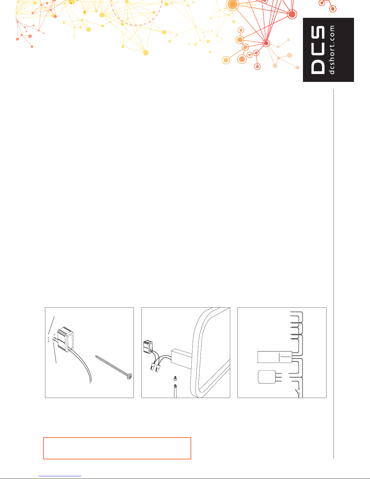
Fig 4.0
Fig 5.0
Fig 6.0
Screw xing approx 14mm
from cable hole centre
10mm
hole
page 3 of 5
DCS
CORTO 350, 550, 750
Electricians, please ensure a copy of the installation
instructions is left with the end user for future reference
2. PRE WIRING - CONTINUED.
• For masonry walls using an angle grinder and masonry cutting disc,
cut a 25mm deep slot from the cable leg to the eventual location of the
transformer, see Fig 2.0
• Place the supplied low voltage wiring in the slot created and render over
directly.
• Black poly tube is supplied to locate the wire in the correct position. Conduit
may also be used but is not essential.
• Low voltage wiring tails should protrude from the nished lined wall approx
150mm to allow for trimming.
3. TOWEL RAIL ASSEMBLY
• Fix the legs to the towel rail using the stainless steel machine screws and
spring washer supplied. See Fig 3.0
• The small grub screw holes must face, what will be, the BOTTOM of the
towel rail.
3. TOWEL RAIL CONNECTION
• Fix the polycarbonate rectangular bushes to the wall using the screws
provided. DO NOT substitute other screws. In particular, DO NOT use
countersunk head screws less than 50mm long. See Fig 4.0
• Use the towel rail as a guide to determine the correct position for the bushes
or use the xing dimensions Table 1.0. MAKE SURE IT IS LEVEL.
• Make the electrical connection to the towel rail using the waterproof wirenut
connectors provided. See Fig 7.0
Waterproof wirenuts MUST NOT BE REUSED. A spare is included.
• The connectors and excess wiring should be pushed back into the leg of
the towel rail.
• If there is a concern that water may enter into the wall cavity, neutral cure
silicone sealant may be applied around the cable where it exits the wall
lining.
• Finally, x the towel rail in position using the small stainless steel screws
provided. See Fig 5.0
• Note: Drilling a 2mm pilot hole makes it much easier to screw in the
self tapping screws. The bushes are moulded from glass reinforced
polycarbonate and are very hard.
5. TIMER AND SWITCH
• The towel rail must have a switch in the bathroom that can be identied
as the towel rail switch. This is typically a separate switch mechanism on
the light switch plate for the bathroom. eg. 3 gang switch plate - lights -
extractor - towel rail
• The supplied ‘ECOTIMER’ is a 230 - 240V device that should be installed
behind the switchplate between the switch and the transformer. See Fig 6.0
To wel Rail
Wall Switch
Transformer
N
L
Mains
12 Volt
Ecotimer
Red
Blue
Brown
To wel Rail
To wel Rail
Fig 4.0
Fig 5.0
Fig 6.0
Screw xing approx 14mm
from cable hole centre
10mm
hole
page 3 of 5