de Gier GW series User manual
GW Installation manual
Standard Winch Rack drive HB series HC series
GW10 GW10L GW10TGA GW40HB GW40HC
GW20 GW30L GW20TGA GW80HB GW80HC
GW30 GW40L GW100HB GW125HC
GW40 GW150HC
GW60
GW80
GW100
GW110S
GW150S
P.INS.GW.01.EN
Version 1 – 2015 / 09 / 06

De Gier B.V., Westlandseweg 9, 2291 PG WATERINGEN, THE NETHERLANDS, Tel. +31 (0)174 292089, Fax +31 (0)174 295644, E-mail: sales@degier.nl
www.degier.eu
Version 1 – 2014 / 06 / 11
2
INSTALLATION MANUAL
Declaration of incorporation
Declaration of incorporation in accordance with the European Machinery Directive 2006/42/EC, Annex II,
No. 1B
DE GIER B.V.
WESTLANDSEWEG 9
NL-2291 PG WATERINGEN
THE NETHERLANDS
We hereby declare that pursuant to article 2G the following partly completed machines are exclusively intended to
be integrated into or mounted in another machine or piece of equipment:
Motor: GW10 / GW20 / GW30 / GW40 / GW80 / GW100 / GW110S / GW150S / GW40HB / GW80HB /
GW100HB / GW40HC / GW80HC / GW125HC / GW150HC / GW10L / GW30L / GW40L /
GW10TGA / GW20TGA
The specic technical documents pursuant to annex VII B have been drawn up and shall be sent on request by
post to the national authorities.
This partly completed machine is compliant with the provisions of the following European directives:
European Machinery Directive 2006/42/EC
European EMC Directive 2004/108/EC
The following harmonised standards (or parts of these standards) have been applied:
EN ISO 12100-1, -2: 04/2004
Safety of machinery: Basic terms, general design principles
EN ISO 14121-1:12/2007
Safety of machinery: Risk assessments
EN 60204-1:06/2007
Safety of machinery: Machinery electrical equipment
EN 60034-5:09/2007
Rotating electrical machines (only electric motors)
This partly completed machine may only be commissioned if it has been established that the machine into which
this partly completed machine needs to be built satises the provisions of the machinery directive.
Authorised compiler of the technical documents:
Rob Sandberg
Director General of De Gier B.V.
Wateringen, 14-10-2014

De Gier B.V., Westlandseweg 9, 2291 PG WATERINGEN, THE NETHERLANDS, Tel. +31 (0)174 292089, Fax +31 (0)174 295644, E-mail: sales@degier.nl
www.degier.eu
Version 1 – 2014 / 06 / 11
3
INSTALLATION MANUAL
Contents
Declaration of incorporation 2
Contents 3
Dimensions 4
Technical specications 5
1 Explanation of symbols and safety instructions 6
2 Product name 8
3 Instructions for use 8
4 Installation 10
5 Electrical connection and commissioning 16
6 Use 18
7 Inspection and maintenance 18
8 Dismounting 19
9 Troubleshooting 20
10 Spare parts and parts replacement 21
11 Disposal 21
12 Warranty 21
Glossary 22
Appendix:
Wiring diagram for 400 V three-phase supply 23
Wiring diagram for 230 V single-phase supply 24
Thank you
for choosing an electric motor gearbox from De Gier Drive Systems’ GW series.
Please pay careful attention to the information in the installation manual during installation and set-up. If you have
any questions or come across problems, please do not hesitate to contact us.
Our service number is: +31 174 - 29 20 89
Or by e-mail: sales@degier.nl
De Gier Drive Systems
De Gier B.V., Westlandseweg 9, 2291 PG WATERINGEN, THE NETHERLANDS, Tel. +31 (0)174 292089, Fax +31 (0)174 295644, E-mail: sales@degier.nl
www.degier.eu
Version 1 – 2014 / 06 / 11
4
INSTALLATION MANUAL
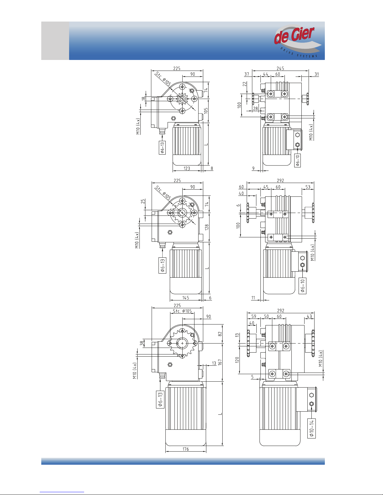
Dimensions
GW10
GW20 - GW30
GW40 - GW150
De Gier B.V., Westlandseweg 9, 2291 PG WATERINGEN, THE NETHERLANDS, Tel. +31 (0)174 292089, Fax +31 (0)174 295644, E-mail: sales@degier.nl
www.degier.eu
Version 1 – 2014 / 06 / 11
5
INSTALLATION MANUAL
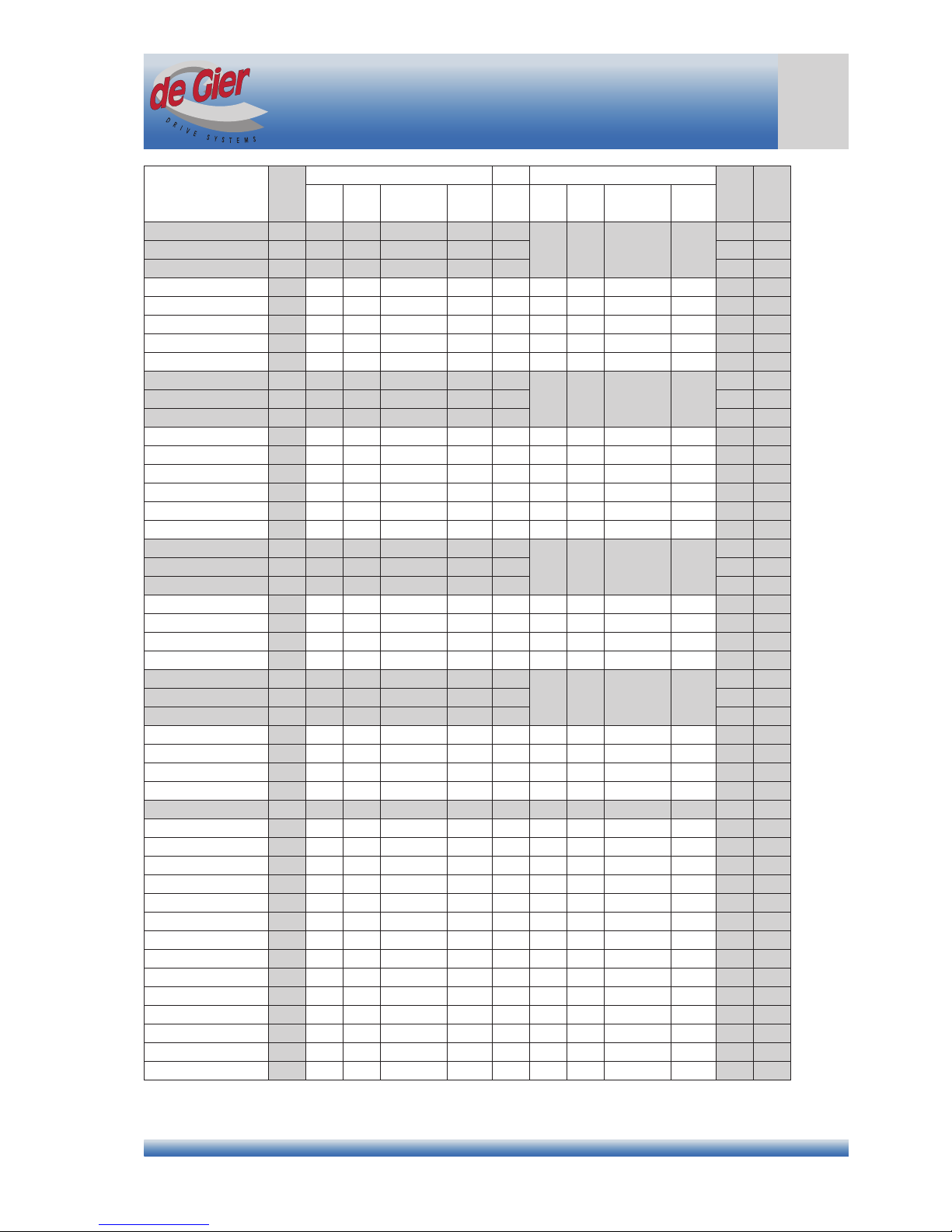
Technical specications
Description T
50 Hz 60 Hz
L m
n P U I n P U I
[Nm] [rpm] [kW] [V] [A] [rpm] [kW] [V] [A] [mm] [kg]
P.GW10.230.13. *1 100 1,3 0,09 230 (~1) 1,3 / -
*2 *2 *2 *2
191 20
P.GW10.230.26. *1 100 2,6 0,18 230 (~1) 1,6 / - 191 23
P.GW10.230.52. *1 100 5,2 0,18 230 (~1) 1,5 / - 191 23
P.GW10.400.13. *1 100 1,3 0,09 230/400 (~3) 0,9/0,5 1,6 0,11 277/480 (3~) 0,9/0,5 191 20
P.GW10.400.26. *1 100 2,6 0,09 230/400 (~3) 0,7/0,4 3,1 0,11 277/480 (3~) 0,7/0,4 168 20
P.GW10.400.52. *1 100 5,2 0,18 230/400 (~3) 1,0/0,6 6,3 0,22 277/480 (3~) 1,0/0,6 191 23
P.GW10.400.150. *1 100 15 0,37 230/400 (~3) 1,7/1,0 18 0,44 277/480 (3~) 1,7/1,0 220 34
P.GW10.400.300. *1 100 30 0,75 230/400 (~3) 3,5/2,0 36 0,90 277/480 (3~) 3,5/2,0 220 34
P.GW20.230.13. *1 200 1,3 0,18 230 (~1) 1,6 / -
*2 *2 *2 *2
191 23
P.GW20.230.26. *1 200 2,6 0,37 230 (~1) 3,2 / - 220 28
P.GW20.230.52. *1 200 5,2 0,37 230 (~1) 3,6 / - 220 28
P.GW20.400.13. *1 200 1,3 0,18 230/400 (~3) 1,2/0,7 1,6 0,22 277/480 (3~) 1,2/0,7 191 23
P.GW20.400.26. *1 200 2,6 0,18 230/400 (~3) 1,2/0,7 3,1 0,22 277/480 (3~) 1,2/0,7 191 23
P.GW20.400.52. *1 200 5,2 0,37 230/400 (~3) 1,7/1,0 6,3 0,44 277/480 (3~) 1,7/1,0 20 28
P.GW20.400.80. *1 200 8 0,37 230/400 (~3) 1,7/1,0 9,6 0,44 277/480 (3~) 1,7/1,0 220 34
P.GW20.400.150. *1 200 15 0,75 230/400 (~3) 3,5/2,0 18 0,90 277/480 (3~) 3,5/2,0 242 34
P.GW20.400.300. *1 200 30 1,5 230/400 (~3) 5,9/3,4 36 1,8 277/480 (3~) 5,9/3,4 242 34
P.GW30.230.13. *1 300 1,3 0,37 230 (~1) 3,2 / -
*2 *2 *2 *2
220 25
P.GW30.230.26. *1 300 2,6 0,37 230 (~1) 3,2 / - 220 28
P.GW30.230.52. *1 300 5,2 0,56 230 (~1) 4,5 / - 220 28
P.GW30.400.13. *1 300 1,3 0,18 230/400 (~3) 1,2/0,7 1,6 0,22 277/480 (3~) 1,2/0,7 191 23
P.GW30.400.26. *1 300 2,6 0,25 230/400 (~3) 1,4/0,8 3,1 0,33 277/480 (3~) 1,4/0,8 220 25
P.GW30.400.52. *1 300 5,2 0,37 230/400 (~3) 1,7/1,0 6,3 0,44 277/480 (3~) 1,7/1,0 220 28
P.GW30.400.150. *1 300 15 1,1 230/400 (~3) 5,4/3,1 18 1,3 277/480 (3~) 5,4/3,1 242 34
P.GW40.230.13. *1 400 1,3 0,37 230 (~1) 3,2 / -
*2 *2 *2 *2
220 28
P.GW40.230.26. *1 400 2,6 0,55 230 (~1) 4,8 / - 242 33
P.GW40.230.52. *1 400 5,2 0,75 230 (~1) 6,0 / - 242 34
P.GW40.400.13. *1 400 1,3 0,25 230/400 (~3) 1,4/0,8 1,6 0,33 277/480 (3~) 1,4/0,8 220 28
P.GW40.400.26. *1 400 2,6 0,37 230/400 (~3) 1,7/1,0 3,1 0,44 277/480 (3~) 1,7/1,0 220 30
P.GW40.400.52. *1 400 5,2 0,55 230/400 (~3) 2,8/1,6 6,3 0,65 277/480 (3~) 2,8/1,6 220 30
P.GW40.400.80. *1 400 8 0,75 230/400 (~3) 3,4/2,0 9,6 0,90 277/480 (3~) 3,4/2,0 242 34
P.GW60.230.52. *1 600 5,2 1,1 230 (~1) 9,5 / - *2 *2 *2 *2 242 34
P.GW60.400.52. *1 600 5,2 0,75 230/400 (~3) 3,5/2,0 6,3 1,13 277/480 (3~) 3,5/2,0 220 30
P.GW80.400.13. *1 800 1,3 0,37 230/400 (~3) 1,7/1,0 1,6 0,44 277/480 (3~) 1,7/1,0 220 30
P.GW80.400.26. *1 800 2,6 0,55 230/400 (~3) 2,6/1,5 3,1 0,66 277/480 (3~) 2,6/1,5 220 32
P.GW80.400.40. *1 800 4 0,75 230/400 (~3) 3,5/2,0 6,3 0,90 277/480 (3~) 3,5/2,0 242 39
P.GW100.400.26. *1 1000 2,6 0,75 230/400 (~3) 3,8/2,2 3,1 0,90 277/480 (3~) 3,8/2,2 242 39
P.GW110S.400.40. *1 1100 4 1,1 230/400 (~3) 5,4/3,1 4,8 1,3 277/480 (3~) 5,4/3,1 242 38
P.GW150S.400.40. *1 1500 4 1,5 230/400 (~3) 6,4/3,7 4,8 1,8 277/480 (3~) 6,4/3,7 280 40
P.GW40HB.400.26. *1 400 2,6 0,37 230/400 (~3) 1,7/1,0 3,1 0,44 277/480 (3~) 1,7/1,0 266 32
P.GW40HC.400.26. *1 400 2,6 0,37 230/400 (~3) 1,7/1,0 3,1 0,44 277/480 (3~) 1,7/1,0 220 30
P.GW80HB.400.26. *1 800 2,6 0,55 230/400 (~3) 2,6/1,5 3,1 0,66 277/480 (3~) 2,6/1,5 266 34
P.GW80HC.400.26. *1 800 2,6 0,55 230/400 (~3) 2,6/1,5 3,1 0,66 277/480 (3~) 2,6/1,5 218 32
P.GW100HB.400.26. *1 1000 2,6 0,75 230/400 (~3) 3,8/2,2 3,1 0,90 277/480 (3~) 3,8/2,2 298 38
P.GW125HC.400.26. *1 1250 2,6 0,88 230/400 (~3) 4,5/2,6 3,1 1,0 277/480 (3~) 4,5/2,6 238 38
P.GW150HC.400.26. *1 1500 2,6 1,1 230/400 (~3) 5,2/3,0 3,1 1,3 277/480 (3~) 5,2/3,0 242 40
*1) Depending on version, K = chain coupling, L = Winch, T = Rack drive
*2) Ask for the possibilities of both 60 Hz electric motors and dual voltage electric motors

De Gier B.V., Westlandseweg 9, 2291 PG WATERINGEN, THE NETHERLANDS, Tel. +31 (0)174 292089, Fax +31 (0)174 295644, E-mail: sales@degier.nl
www.degier.eu
Version 1 – 2014 / 06 / 11
6
INSTALLATION MANUAL
1. Explanation of symbols and safety instructions
This installation manual is part of the delivery of the electric motor gearbox and must be kept in the vicinity of the
motor gearbox.
1.1 Explanation of symbols and instructions in this manual
Important procedures are emphasised in this user manual in a separate box with the initial lines printed in bold.
See below for an explanation of the various instructions you will encounter in this manual.
Symbol Meaning Unit Symbol Meaning Unit
T Torque Nm n Rotational speed rpm
P Power kW L Length mm
U Voltage V m Mass kg
I Current A
Tip - Hazard -
Note - Electrical hazard -
Instruction Explanation
Tip
Attention!
Caution!
Warning!
Risk of injury or death!
Gives the user suggestions and advice for carrying out specic tasks easily or more
practically.
Remarks with supplementary information for the user. These remarks draw the user’s
attention to potential problems.
Material damage can occur when the procedures are not followed carefully.
Serious injury to the user and/or serious damage to the product can occur if the
procedures are not followed carefully.
The user’s life is directly endangered.
1.2 Explanation of symbols on the motor gearbox
The following symbols are shown on the motor gearbox.
Symbol Meaning Symbol Meaning
Do not spray Fit the red vent plug
Electrically live parts PE connection point (earth)
Read the documentation
Explanation of symbols

De Gier B.V., Westlandseweg 9, 2291 PG WATERINGEN, THE NETHERLANDS, Tel. +31 (0)174 292089, Fax +31 (0)174 295644, E-mail: sales@degier.nl
www.degier.eu
Version 1 – 2014 / 06 / 11
7
INSTALLATION MANUAL
Safety instructions
1.3 General safety instructions
• Read the installation manual carefully and in full;
• Check that the delivery is complete before starting to install the motor gearbox;
• Strictly observe the step-by-step procedures set out in the installation manual;
• Observe all of the information in the installation manual, in particular all information relating to safety, use,
maintenance and servicing;
• Keep the installation manual in a safe place throughout the entire service life of the product;
• Switch off power to the motor gearbox before starting to work on the motor gearbox or in its immediate vicinity;
• Clean up the hazard area and leave it before switching the power back on;
• Improper installation, commissioning, maintenance etc. of the motor gearbox can lead to personal injury and/
or material damage due to the high torque of the motor gearbox;
• Operate the motor within its electrical ratings to avoid damage to the motor, drive train or other parts of the
system;
• Do not allow people to stand under or close to suspended loads;
• Never loosen screws, couplings or other parts while the drive train is under load;
• Also observe national legislation and guidelines regarding working conditions and safety.
1.4 General safety instructions
• Switch the power off before starting to work on the motor gearbox or the system and lock it out (for example,
with a padlock) to prevent it from being switched back on. This also applies to auxiliary circuits, such as limit
switches or standby heating. It is not sufcient to switch off the controller by selecting ‘stop’ or ‘0’. The motor
gearbox may also continue to operate in the «Stop» or «0» position in response to higher-level functions, such
as signals from wind or rain sensors;
• Attached or driven parts may have a shorter service life than the motor gearbox itself;
• With a three-phase supply, swapping two of the phases reverses the direction of rotation of the motor gearbox,
which can affect the operation of the limit switch mechanism;
• De Gier supplies motor gearboxes that are self-braking, but this function may not be effective under certain
conditions. We strongly recommend that for hoisting applications you use a motor gearbox equipped with a
mechanical brake and mount a fall-arrest brake on the driven shaft;
• With attached or driven components there is a risk of becoming trapped or injured. Amongst other things, the
safety distances set out in EN 349 and EN 13857 must be observed and suitable precautions must be taken,
such as safety devices or a dead-man vigilance system;
• The housing of the motor gearbox can reach temperatures above 60°C / 140°F. Fit a protective cover if
necessary, depending on the location of the motor gearbox;
• Despite careful planning and compliance with all regulations, some risks cannot be prevented.
1.5 Qualied staff
All activities described below must be performed by qualied staff. Qualied staff means persons who, based
upon their training, experience and/or education, have obtained sufcient knowledge of the applicable standards,
provisions, accident prevention regulations and operating conditions and are thus able to identify and avoid
potential hazards during relevant activities (for instance, installers recommended by De Gier). Approval by the
safety ofcer for the overall plant or system is always required before work may be carried out.

De Gier B.V., Westlandseweg 9, 2291 PG WATERINGEN, THE NETHERLANDS, Tel. +31 (0)174 292089, Fax +31 (0)174 295644, E-mail: sales@degier.nl
www.degier.eu
Version 1 – 2014 / 06 / 11
8
INSTALLATION MANUAL
2 Product name
2.1 Manufacturer
The address details of De Gier are set out below;
De Gier B.V.
Westlandseweg 9
NL-2291 PG Wateringen
The Netherlands
I : www.degier.eu
E : sales@degier.nl
T : +31 174 – 292 089
F : +31 174 – 295 644
2.2 Rating plate
Let op! De prefab aandrijfassen van de U
2.3 Description
The structure of the item number on the above rating plate is set out below with an explanation of the possible
versions.
CODE SERIES TORQUE
[ x 10 Nm]
VOLTAGE
[V]
RPM
[ x 10-1 rpm]
VERSION
P GW 10 400 26 K
Possible versions Possible versions
K Chain coupling L1 Single cable drum
K100 1” Drive tube L2 Dual cable drum
K125 1,25” Drive tube LB Belt winch drum
K200 2” Drive tube T Toothed rack
L Winch drum Txxx Stroke length xxx mm
3. Instructions for Use
3.1 Intended use
GW motor gearboxes are intended for ventilation, screening and hoisting applications, such as:
• Ridge ventilation: linear-drive roof ventilation systems, for example in greenhouses, garden centres, ofce
buildings, halls, stables or polytunnels;
• Side ventilation: linear-drive side ventilation systems, for instance in greenhouses, facades, halls, or roll-up
curtains or plastic tarps for stables or greenhouses;
• Screening: for example, screens driven by cables or toothed racks in greenhouses or strip curtain systems;
• Hoisting applications: for example, growing tube or chrysanthemum (hoisting) heating. Only permitted with
fall-arrest brake protection.
Product name
1
2
3
4
5
6
7
Item number
Potentiometer resistance (optional)
Motor identication number
Production date
Serial number
De Gier barcode
De Gier address details
Example of an identication sticker

De Gier B.V., Westlandseweg 9, 2291 PG WATERINGEN, THE NETHERLANDS, Tel. +31 (0)174 292089, Fax +31 (0)174 295644, E-mail: sales@degier.nl
www.degier.eu
Version 1 – 2014 / 06 / 11
9
INSTALLATION MANUAL
Instructions for use
3.2 Special versions
The following special versions (amongst others) can be supplied in consultation with the manufacturer (not for
every type):
• 24 VDC;
• Version for non-standard mains voltage and/or frequency;
• Versions for use with high relative air humidity (RH > 60%);
• Non-standard approvals.
3.2 Conditions of use
The following conditions of use are applicable when using the motor gearbox:
• Operating ambient temperature range:
• Above 0.6 kW: -15°C to 60°C [5°F to 140°F];
• Below 0.6 kW: +5°C to 60°C [32°F to 140°F];
• Max. force on output shaft:
• GW10: radial 1,000 N, axial 400 N
• All other types with the exception of GW10: radial 4,000 N, axial 400 N;
• Hoisting of freely suspended loads (not persons), such as a growth tube or chrysanthemum (hoistable) heating
frame or assimilation lighting, is only permitted with a fall-arrest brake protection system;
• The motor gearboxes are suitable for S3-30% operation;
• The maximum continuous on time is 25 minutes;
• The motor gearbox may be cycled a maximum of 3 times per minute;
• The service life of the motor gearbox increases signicantly with low loads and switching cycles which allow
intermediate cooling of the motor gearbox.
3.3 Restrictions on use
Structural modications to the motor gearbox are not permitted. Any such modications render the manufacturer’s
warranty null and void and relieve the manufacturer of liability for any consequences. In addition, the following
restrictions are applicable with regard to the use of the motor gearbox:
• Do not load the motor gearbox or drive train with a torque greater than the maximum specied torque;
• Do not use the motor gearbox to operate parts located in the immediate vicinity (within easy reach) of people.
Maintain safe distances in accordance with EN ISO 13857;
• Do not expose the motor gearbox to direct water spray, rain or snow;
• Do not use the motor gearbox to operate smoke and heat exhaust ventilation systems compliant with NEN
6093 or DIN 18232;
• Do not use the motor gearbox to operate automatic doors or gates used by people;
• Do not use the motor gearbox in explosion hazard areas if express permission has not been granted to do so.
3.4 Unintended use (misuse)
We expressly warn against the following types of unintended use:
• Do not use the motor gearbox for lifting suspended loads in areas in which people are present;
• Do not use the motor gearbox for transporting people (for example, for passenger lifts, etc.).
3.5 Storage
To safeguard the service life and correct functioning of the motor gearboxes, the following rules must be followed:
• Ensure that the motor gearboxes are stored in a dust-free and moisture-free environment;
• The relative air humidity of the storage location must be less than 50%;
• Store the motor gearboxes at temperatures between -15 and +60°C [5°F to 140°F];
• Avoid sudden changes in temperature to prevent the formation of condensation.
If you wish to store the motor gearboxes for a lengthy period of time, you can use preservatives to protect the
unpainted surfaces, such as threaded holes and mounting surfaces for chain couplings, against corrosion.

De Gier B.V., Westlandseweg 9, 2291 PG WATERINGEN, THE NETHERLANDS, Tel. +31 (0)174 292089, Fax +31 (0)174 295644, E-mail: sales@degier.nl
www.degier.eu
Version 1 – 2014 / 06 / 11
10
INSTALLATION MANUAL
4 Installation
Installation of the motor gearbox and adjustment of the limit switches may only be carried out by qualied staff (see
Section 1.5).
4.1 Installation positions and vent plug
Consider the following points when determining the installation position:
• For both side mount and foot mount congurations, use M10 bolts with a strength class of at least 8.8
threaded into the motor gearbox by 10 to 15 mm;
• Maintain a clearance of approximately 500 mm above the black cover for adjusting the limit switches;
• When mounted in a dusty or humid space, the motor gearbox must be tted in a suitable enclosure;
• Keep approximately 300 mm of space free behind the motor so that in the event of power failure the motor
gearbox can be operated manually or with a drill (maximum speed 250 rpm) using the hex socket in the end of
the motor shaft.
Every gear unit is pre-lled during manufacture with the correct type and quantity of oil. Every gear unit is also
tted with two plastic screw plugs. The higher of the two plugs in the selected installation position must be replaced
by the supplied red vent plug, with the supplied gasket tted behind the vent plug.
4.2 Mounting the motor gearbox
The motor gearbox is normally coupled to the load bGy a chain coupling to the drive shaft. See the details below
for maximum torques and maximum alignment error.
Warning!
● Do not exceed the maximum rated torque of chain couplings and accessories.
● The load must be distributed evenly over both ends of the shaft. Preferably fit the drive unit in the middle
of the drive train.
● The maximum angle a chain coupling is allowed to make must remain below the specified value.
Type of chain coupling Max. torque [Nm] Max. angle
08B Z12 (1/2” x 5/16”) 120 1°
08B Z16 (1/2” x 5/16”) 240 4°
10B Z16 (5/8” x 3/8”) 420 4°
12B Z16 (3/4” x 7/16”) 675 3°
12B Z18 (3/4” x 7/16”) 760 3°
Mount congurations, 1; side mount, 2; foot mount Installation positions and vent plug
Installation

De Gier B.V., Westlandseweg 9, 2291 PG WATERINGEN, THE NETHERLANDS, Tel. +31 (0)174 292089, Fax +31 (0)174 295644, E-mail: sales@degier.nl
www.degier.eu
Version 1 – 2014 / 06 / 11
11
INSTALLATION MANUAL
Installation
4.2.1 Transport
Risk of injury or death! Falling objects can present a danger to people!
● Transport the motor gearbox carefully and avoid shocks.
● Force causes damage to the motor gearbox.
● Use a work platform, or lift the motor gearbox using hoisting equipment and appropriate slings tted
around the output shaft.
4.2.2 Foot mounting and side mounting
• With foot mounting, align the output shaft with the drive tube using shim washers under the feet of the motor
gearbox;
• Secure the motor gearbox with four bolts for foot mounting or three bolts for side mounting. Tighten the bolts to
50 Nm.
Attention! The output shaft and the drive train must be in a single line.
● If alignment errors cannot be avoided, use a exible coupling.
● Chain couplings can accommodate an alignment error of 1 to 4 degrees maximum, depending on the
coupling type.
● For larger angles a universal joint can be used.
If you use wood screws or wall anchors for mounting, you must determine the right screws and tightening torques
yourself, provided they have the same strength as M10 8.8 bolts.
4.3 Mounting the welding socket
1. Weld the welding socket to the tube to be driven.
2. Then t the welding socket onto the output shaft of the motor gearbox using the pre-tted bolt (tightening
torque 8 Nm) so the coupling cannot move axially and slip off the shaft.
Attention! The output shaft and the drive train must be in a single line.
● If alignment errors cannot be avoided, use a exible coupling.
● Chain couplings can accommodate an alignment error of 1 to 4 degrees maximum, depending on the
coupling type.
● For larger angles a universal joint can be used.
4.4 Mounting the chain coupling
1. Fit the two halves of the coupling on the output shaft and the drive tube;
2. Turn the coupling halves until the teeth are aligned;
3. Wrap the dual chain around the teeth of the coupling sections so the ends of the chain are on top;
4. Fit the chain as shown in the diagrams below.
Tip
De Gier can supply chain couplings which can be used to compensate for limited alignment errors.
Different types can be combined with each other.
1 2 3 4
De Gier B.V., Westlandseweg 9, 2291 PG WATERINGEN, THE NETHERLANDS, Tel. +31 (0)174 292089, Fax +31 (0)174 295644, E-mail: sales@degier.nl
www.degier.eu
Version 1 – 2014 / 06 / 11
12
INSTALLATION MANUAL
4.5 Adjusting the limit switches
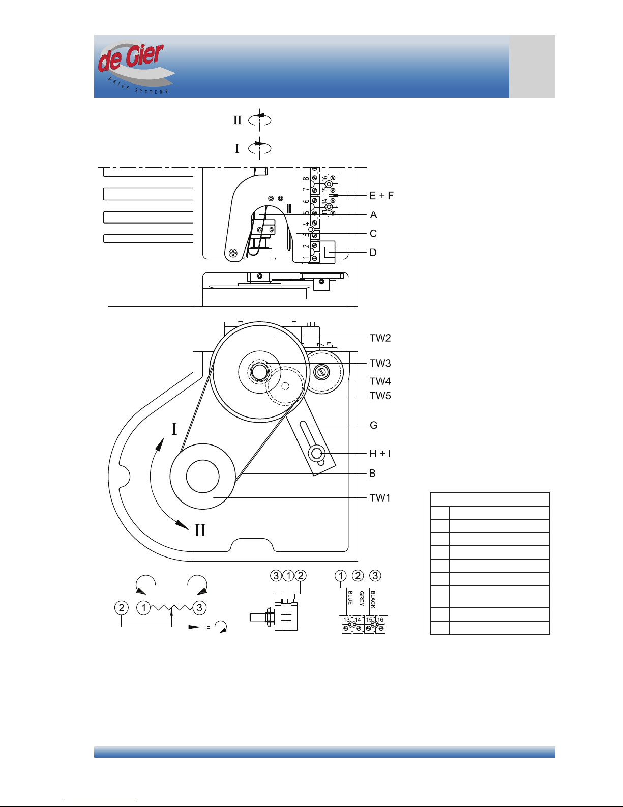
Use the following procedure and the gures on page 13 to adjust the built-in limit switches.
Operation
• The switch shaft (A) of the limit switch mechanism is driven by a toothed belt from the output shaft of the motor
gearbox.
• On the switch shaft (A) there are two switch nuts (E) consisting of a knurled nut (D) and an adjustment ring
(C). The adjustment ring can be secured to the knurled nut (D) by a short set screw (G) and a long set screw
(H).
• The switch nuts (E) move along the switch shaft (A) in direction I or II, depending on the direction of rotation of
the motor gearbox. When the switch nut reaches the stop nut (B) at the end of the switch shaft and is not able
to travel any further, the switch nut (E) will start to turn with the switch shaft (A).
• The limit switch has two spring arms (F), each of which actuates a working switch and an emergency switch:
either working switch S11 and emergency switch S21 for rotation direction I, or working switch S12 and
emergency switch S22 for rotation direction II.
• The emergency switch (S21 or S22) is a safety device and is only actuated if the working switch (S11 or S12)
does not stop the motor gearbox on time.
• The long set screw (H) of each switch nut (E) is located between the spring arms. If one of the switch nuts
reaches its stop nut, the switch nut rotates with the shaft and the long set screw actuates the working and
emergency limit switches corresponding to direction of travel via the spring arm (F).
Mounting the limit switch (standard factory-tted)
1. Remove the black plastic protective cover from the motor gearbox;
2. Fit the complete limit switch in its intended position;
3. Ensure that both long set screws (H) are located between the spring arms (F) so the spring arms release their
limit and emergency switches when the switch nut starts to turn with the shaft;
4. Secure the limit switch above the switch shaft (A) by screwing the two Phillips screws hand-tight.
Adjustment procedure
1. Remove the black plastic protective cover to reveal the limit switch mechanism and the toothed belt;
2. Check whether the adjustment rings (C) are free to move on the knurled nuts (D) by manually moving the
knurled nuts along the switch shaft (A). If they do not move freely, loosen the set screws by one turn (do not
remove);
3. Use a hex key to rotate the motor gearbox from the rear of the motor and determine which working switch
(S11 or S12) marks the start and end points in your application;
4. Using a hex bit, move the motor gearbox to the start point (see the diagram below);
Caution!
When driving the electric motor with a hex bit, keep the speed below 250 rpm to avoid damage to the hex
socket at the rear of the motor shaft.
5. Hand-tighten the associated knurled nut (D) against its stop nut (B);
6. Fit the included hex key (X) in the long set screw (H) and turn the adjusting ring (C) over the knurled nut (D)
until the spring arm moves away from the plastic case and you hear a soft click. Then tighten the long set
screw on the knurled nut to 2 Nm;
7. Tighten the short set screw (G) of the switch nut (E) that has just been adjusted to 2 Nm;
8. Using a hex bit, move the motor gearbox to the other end point;
9. Repeat steps 5 through 7 to adjust the other working switch;
10. Replace the black plastic protective cover on the motor gearbox and tighten the four screws again;
11. Keep this manual with adjustment instructions in a suitable place.
Tip
To avoid mistakes in the future, mark the switches to indicate which one limits the start position and which
one limits the end position.
Adjusting the limit switches

De Gier B.V., Westlandseweg 9, 2291 PG WATERINGEN, THE NETHERLANDS, Tel. +31 (0)174 292089, Fax +31 (0)174 295644, E-mail: sales@degier.nl
www.degier.eu
Version 1 – 2014 / 06 / 11
13
INSTALLATION MANUAL
Adjusting the limit switches
Hex key and spare set screws
Adjusting the limit switch
Parts
A Switch shaft (1x)
B Stop nut (2x)
C Adjustment ring (2x)
D Knurled nut (2x)
E Switch nut (2x)
F Switch spring (2x)
G Short set screw (2x)
H Long set screw (2x)
Equipment and spare parts
included
X Hex key 2 mm
Y Spare set screw M4x20
Z Spare set screw M4x6
Driving the motor gearbox using a hex bit
Attention!
Do not keep any loose parts or documents under the black plastic protective cover, since they may impair
the operation of the limit switch mechanism.

De Gier B.V., Westlandseweg 9, 2291 PG WATERINGEN, THE NETHERLANDS, Tel. +31 (0)174 292089, Fax +31 (0)174 295644, E-mail: sales@degier.nl
www.degier.eu
Version 1 – 2014 / 06 / 11
14
INSTALLATION MANUAL
4.6 Potentiometer (optioneel)
Application
The potentiometer kit is only intended to be used with GW motor gearboxes from De Gier
• The potentiometer has a maximum range of 10 turns and is available with the following resistance values: 0.5
kΩ, 1.0 kΩ, 2.0 kΩ, 5.0 kΩ and 10 kΩ;
• Operating temperature range: +1°C to +60°C.
Operation
The switch shaft (A) of the limit switch mechanism is driven by a toothed belt from the output shaft of the
motor gearbox. A gear set reduces the number of turns of the switch shaft to a maximum of nine turns of the
potentiometer shaft. Depending on the gear ratio, this gear set consists of two or three gears (if there are only two
gears, the bracket (G) and gear TW5 are not included).
Mounting
Use the following procedure to retrot the potentiometer kit:
1. Remove the black plastic protective cover and the side plate of the motor gearbox to reveal the limit switch
mechanism and toothed belt;
2. Slide the toothed belt (B) off the plastic gear wheel (TW2);
3. Remove the retaining rings and the gear wheel (TW2) from the switch shaft (A);
4. Fit the gear wheel (TW3) on the switch shaft (A);
5. Loosen the two screws on the limit switch (C) and remove the limit switch;
6. Slide the terminal block (E) over the plastic bracket (F) and click them together under the limit switch (C);
7. Fit the potentiometer (D) and ret the limit switch (C), taking care to ensure it is tted correctly;
8. Slide the gear wheel (TW4) onto the potentiometer shaft (D). Do not tighten this gear wheel yet.
9. Fit the gear wheel (TW5), if included, on the bracket (G); otherwise continue with step 12;
10. Fit the bracket (G) in place with the bolt (H) and lock washer (I), but do not tighten the bolt;
11. Fit the gear wheel (TW5) on the bracket (G) between the gear wheels (TW3 and TW4) and tighten the bracket.
The gear wheel (TW5) should be pressed very lightly against the other gear wheels. The gears should turn
smoothly and easily;
12. Ret the retaining rings and the gear wheel (TW2) on the switch shaft (A);
13. Slide the toothed belt (B) over the gear wheel (TW2);
14. Adjust the limit switch mechanism (see adjustment instructions in Section 4.5);
15. Adjust the potentiometer and secure the gear wheel (TW4) on the potentiometer shaft;
16. Fit the side plate and the black plastic protective cover.
4.7 I-DE Intelligent digital encoder (optional)
Application
The intelligent digital encoder (I-DE) is a multifunction position encoder which provides extremely accurate
information about the position of the GW motor gearbox. It has digital and analogue outputs. This position encoder
can easily be tted in place of a conventional potentiometer.
More information about tting, connecting and adjusting the I-DE can be found in the specic manual for the I-DE.
Potentiometer
De Gier B.V., Westlandseweg 9, 2291 PG WATERINGEN, THE NETHERLANDS, Tel. +31 (0)174 292089, Fax +31 (0)174 295644, E-mail: sales@degier.nl
www.degier.eu
Version 1 – 2014 / 06 / 11
15
INSTALLATION MANUAL
Potentiometer
Limit switch mechanism with potentiometer
Parts
A Switch shaft
B Toothed belt
C Limit switch
D Potentiometer
E Terminal block
F Plastic bracket
G Bracket for intermediate
gear wheel (optional)
H Bolt M5 x 8
I Washer M5
De Gier B.V., Westlandseweg 9, 2291 PG WATERINGEN, THE NETHERLANDS, Tel. +31 (0)174 292089, Fax +31 (0)174 295644, E-mail: sales@degier.nl
www.degier.eu
Version 1 – 2014 / 06 / 11
16
INSTALLATION MANUAL
5. Electrical connection and commissioning
Connecting and commissioning may only be carried out by qualied staff.
Risk of injury or death! Risk of injury or death due to electrical or mechanical forces!
Before starting to work on the motor gearbox or related parts, always switch the power off at the master
switch or operating switch and lock it out with a padlock to prevent switching on again.
5.1 Mains connection for single-phase AC motors
Caution
The maximum permissible deviation of the mains voltage from the voltage stated on the rating plate of the
motor is 5%.
The wiring diagram can be found in the appendix on page 24.
1. Remove the cover from the terminal block of the electric motor;
2. Insert the cable through the cable gland and rubber gasket;
3. Connect the green/yellow lead to the PE terminal (earth);
4. Connect the neutral lead (N) to terminal U1 and the live lead (L) to terminal V1 or W1 as shown on the wiring
diagram, depending on the desired direction of rotation;
5. Using a hex bit, move the motor gearbox to a position between the two limit switches;
6. Check the direction of rotation of the output shaft in relation to the limit switch and the control cabinet. If
necessary, switch the wiring between V1 and W1 (see diagram);
7. Fit the terminal block cover and gasket back on the motor and tighten the cable gland;
8. Make sure that the cables are clear of any moving parts.
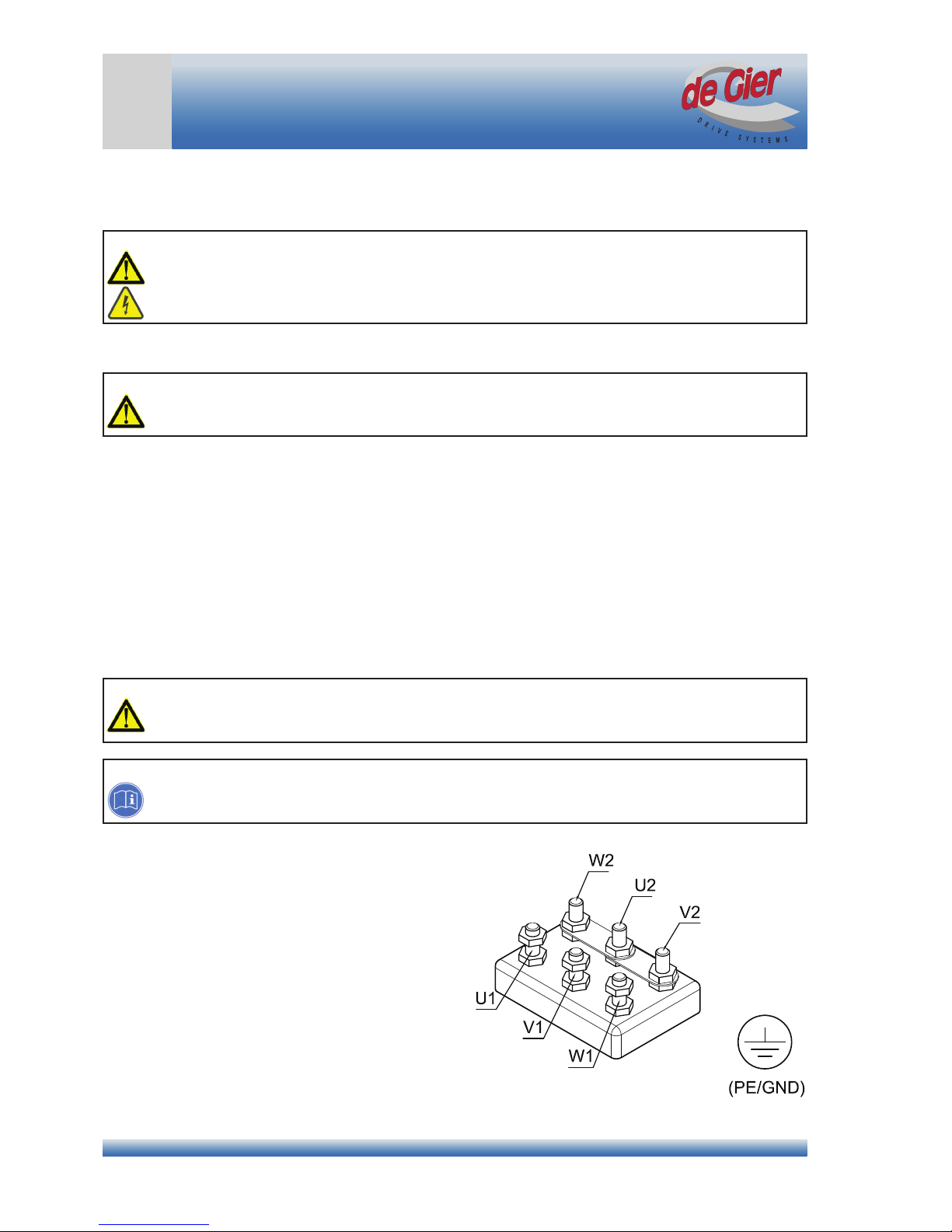
5.2 Mains connection for three-phase AC motors
Caution
The maximum permissible deviation of the mains voltage from the voltage stated on the rating plate of the
motor is 10%.
Attention!
Swapping the supply voltage phase connections changes the direction of rotation of the drive. A switch in
phase will affect the operation of the limit switch mechanism.
The wiring diagram can be found on page 23.
1. Remove the cover from the terminal block of the
electric motor;
2. Insert the cable through the cable gland and rubber
gasket;
3. Connect the green/yellow lead to the PE terminal
(earth);
4. Connect phase L1 to terminal U1, phase L2 to terminal
V1 and phase L3 to terminal W1 (see diagram)
5. Using a hex bit, move the motor gearbox to a position
between the two limit switches;
6. Check the direction of rotation of the output shaft in
relation to the limit switch and the control cabinet, and
swap two phases if necessary;
7. Fit the terminal block cover and gasket back on the
motor and tighten the cable gland;
8. Make sure that the cables are clear of any moving
parts.
Electrical connection
Terminal block for three-phase motor

De Gier B.V., Westlandseweg 9, 2291 PG WATERINGEN, THE NETHERLANDS, Tel. +31 (0)174 292089, Fax +31 (0)174 295644, E-mail: sales@degier.nl
www.degier.eu
Version 1 – 2014 / 06 / 11
17
INSTALLATION MANUAL
Electrical Connection
5.3 Mains connection for DC motors
Caution
The maximum permissible deviation of the mains voltage from the voltage stated on the rating plate of the
motor is 10%.
The wiring diagram is supplied upon request.
1. Remove the cover from the terminal block of the electric motor;
2. Insert the cable through the cable gland;
3. Connect the green/yellow lead to the PE terminal (earth);
4. Connect the 24 VDC lead to terminal A1 and neutral lead to terminal A2;
5. Using a hex bit, move the motor gearbox to a position between the two limit switches;
6. Check the direction of rotation of the output shaft in relation to the limit switch and the control cabinet; if
necessary swap the leads on A1 and A2;
7. Fit the terminal block cover and gasket back on the motor and tighten the cable gland;
8. Make sure that the cables are clear of any moving parts.
5.4 Connecting the limit switch
Attention! Observe the maximum (peak) switching current rating of 6 A at 250 VAC.
The optional Goldline limit switches from De Gier, which have gold-plated contacts, must be used if the
control voltage is less than 30 V or the control current is less than 400 mA.
1. Remove the black plastic protective cover from the motor gearbox;
2. Insert the cable through the cable gland;
3. Connect the working and emergency switches as indicated in the diagram below;
4. Fit a jumper between contacts 1 and 7;
5. Fit a jumper between contacts 6 and 10;
6. Make sure that the cables are free and tighten the cable gland;
7. Re-t the black plastic protective cover on the motor gearbox.
Wiring diagram for working and emergency switches

De Gier B.V., Westlandseweg 9, 2291 PG WATERINGEN, THE NETHERLANDS, Tel. +31 (0)174 292089, Fax +31 (0)174 295644, E-mail: sales@degier.nl
www.degier.eu
Version 1 – 2014 / 06 / 11
18
INSTALLATION MANUAL
5.5 Commissioning
Caution!
Operate the drive in manual mode at rst; not in automatic mode.
After the motor gearbox has been installed, connected and adjusted, a test run in the system is necessary. Pay
attention to the following points during the test run:
1. Ensure that no people or objects are within the working area of the motor gearbox and connected parts;
2. Check whether the vent plug is tted in the correct position (see Section 4.1);
3. Check the operation of the system in manual mode. The direction of movement must match the indication on
the control panel;
4. Check that the limit switches and stop positions are properly adjusted, and re-adjust them if necessary (see
Section 4.5).
Tip
Install an operating hours counter.
6. Use
6.1 Noise level
The noise level (sound pressure level) at a distance of one metre is below 60 dB(A).
6.2 Heating
• The motor gearbox is not suitable for continuous operation.
• The motor gearboxes are suitable for S3-30% operation;
• The maximum continuous on time is 25 minutes;
• The motor gearbox may be cycled at most three times per minute.
Warning! Risk of burns!
The outside of the drive unit can reach temperatures in excess of 60°C.
We recommend tting a protective cover if the unit is within easy reach.
7. Inspection and maintenance
Inspection and maintenance tasks may only be carried out by qualied staff (see Section 1.3).
7.1 Maintenance intervals
Risk of injury or death! Risk of injury or death due to electrical or mechanical forces!
Before starting to work on the motor gearbox or related parts, always switch the power off at the master
switch or operating switch and lock it out with a padlock to prevent switching on again.
Every 6 months
• Check for increased noise level
• Lubricate chain couplings (oil viscosity 80 cST to 120 cST at 20°C)
Every year
• Check and re-tighten mounting bolts
• Check couplings for wear and corrosion
• Check the limit and emergency switch mechanism for corrosion
• Re-tighten set screws in switch mechanism
• Check the wiring of the motor and the limit and emergency switch mechanism
• Check the play of the output shaft
Commissioning

De Gier B.V., Westlandseweg 9, 2291 PG WATERINGEN, THE NETHERLANDS, Tel. +31 (0)174 292089, Fax +31 (0)174 295644, E-mail: sales@degier.nl
www.degier.eu
Version 1 – 2014 / 06 / 11
19
INSTALLATION MANUAL
7.2 Maintenance tasks
The motor gearbox has lifetime lubrication. Changing the gear oil is usually unnecessary.
Caution!
For the following tasks it must be ensured that the load cannot start moving by itself after it is
disconnected from the drive.
7.2.1 Checking worm gear wear and shaft play
1. Put the motor gearbox in an unloaded position, for example with the vent closed;
2. Switch off the power;
3. Disconnect the motor gearbox from the drive train, so the output shaft should be able to turn freely;
4. Check the play in the gear unit by turning the output shaft of the drive.
If there is clearly noticeable play, the drive should be dismounted and returned to the manufacturer for inspection.
8 Dismounting
Dismounting may only be carried out by qualied staff (see Section 1.3).
Risk of injury or death! Risk of injury or death due to electrical or mechanical forces!
Before starting to work on the motor gearbox or related parts, always switch the power off at the master
switch or operating switch and lock it out with a padlock to prevent switching on again.
Risk of injury or death! Risk of injury or death due to falling objects!
• Cordon off the hazard area with barrier tape.
• Use a work platform, or lift the motor gearbox using hoisting equipment and appropriate slings tted
around the output shaft.
Attention!
Motor gearbox components may only be replaced or repaired by an authorised service representative of
De Gier
8.1 Dismounting the motor gearbox from the drive train
1. Put the drive unit of the motor gearbox in an unloaded position, for example with the vent closed;
2. Disconnect all wiring;
3. Disconnect the output shaft from the driven system;
4. Replace the vent plug with an M12 sealing plug;
5. Dismount the motor gearbox unit from the system.
Maintenance and dismounting
De Gier B.V., Westlandseweg 9, 2291 PG WATERINGEN, THE NETHERLANDS, Tel. +31 (0)174 292089, Fax +31 (0)174 295644, E-mail: sales@degier.nl
www.degier.eu
Version 1 – 2014 / 06 / 11
20
INSTALLATION MANUAL
Troubleshooting
9 Troubleshooting
Troubleshooting may only be performed by qualied staff (see Section 1.3).
Risk of injury or death! Risk of injury or death due to electrical or mechanical forces!
Before starting to work on the motor gearbox or related parts, always switch the power off at the master
switch or operating switch and lock it out with a padlock to prevent switching on again.
9.1 Fault: power outage
• Disconnect power to prevent unintentional operation of the motor gearbox during work activities;
• In emergency situations the motor gearbox can be turned to the desired position using an electric drill and a
hex bit inserted in the hex socket on the motor shaft.
Caution!
When driving the motor with a hex bit, keep the speed under 250 rpm to protect the socket in the motor
shaft.
9.2 Fault: drive does not run
• Check the motor protection switch and its setting. If the fault occurs again, there may be an overload;
• Check whether the emergency switch of the motor gearbox is actuated;
• Check the wiring, including the limit switch wiring;
• For motor gearboxes with 3-phase mains supply, check whether rotation directions I and II correspond to limit
switches S11 and S12;
• If the thermal protection (bimetallic switch) of the motor gearbox has tripped, the motor gearbox must cool
down for approximately 20 minutes. After this it can be used again. If this protection trips repeatedly, contact
your installer to resolve this problem.
9.3 Fault: travel past end position
• Check whether the set screws in the limit switch mechanism are tight, and check the adjustment of the limit
switches;
• Re-adjust the limit switches if necessary (see Section 4.5);
• Check the operation of limit switches S11 and S12 and emergency switches S21 and S22. The switches must
be wired and monitored as normally closed (NC) contacts;
• Check the operation of the relay and replace it if necessary.
9.4 Fault: oil leak
• Check whether the vent plus is tted and installed in the right place (see Section 4.1);
• Contact the installer if oil leaks occur.
9.5 Fault: humming noise from motor
• Check the voltages on all three phases, which should all be the same and correspond to the value on the
motor rating plate;
• Check that all nuts on the terminal block are properly tightened;
• Contact the installer if the fault persists.
This manual suits for next models
21
Table of contents
Other de Gier Engine manuals


