KIRLOSKAR R1040 User manual

R1040 MAINTENANCE MANUAL
Page 1 of 48
Index
Sr.
No.
Topic Page
Nos
1 General 2
1.1 Service and Maintenance 2
1.2 Maintenance and Repairs 2
1.3 Safety 2
2 Engine details 2
2.1 Engine Name Plate 2
2.2 Engine illustrations 3
2.3 Engine lifting device 4
2.4
Lube oil system
5 – 8
2.5
Fuel supply system
9-10
2.6 Cooling System 11
2.7 Electrical System 12
3 Engine operation
3.1 Commissioning 13-16
3.2 Starting 16
3.3 Stopping 17
3.4 Operating conditions 18
3.5 Running-in period 19
4 Routine Maintenance 20
4.1 Maintenance Schedule 20
4.2 Top Overhaul and Major Overhaul Periods 21
5 Service and Maintenance 21
5.1 Maintenance of Lubrication system 21 - 27
5.2
Maintenance
of
Fuel
System
28
5.3
Maintenance
of
Cooling
System
29-30
5.4
Maintenance of Dry type air cleaner
31-34
5.5 Belt drives 35
5.6
Adjustments
36
5.7
Maintenance of Electrical Equipment
37
5.8
Checking of Fasteners
37
6
Troubleshooting and Remedial measures
38
6.1
Troubleshooting
38
6.2
Useful tips for Turbocharger
40
6.3
Periodical Inspection of Turbocharger for Generating set application
41
6.4
Recommendation for Turbocharger operation and maintenance
41
7
Instruction Manual for Electronic Governor
42
8
Engine preservation
43
8.1
Recommended Preservatives
43
8.2
Preservation Procedure
43
8.3
Commissioning
of
Preserved
Engine
44
9
Tightening Torque, Settings
45
9.1
Tightening Torque
45
9.2
Settings
46
10
Fuel timing
47

R1040 MAINTENANCE MANUAL
Page 2 of 48
1 General
Your engine needs
•Clean High Speed Diesel oil.
•Lubricating oil of specified quality and viscosity grade.
•Fresh air for combustion of fuel, for cooling of engine.
•Proper ventilation of engine compartment to avoid re-circulation of hot air.
•Genuine spare parts for its maintenance.
1.1 Service and Maintenance
Sound service and maintenance practices will ensure that the engine continues to
meet your requirements. Recommended service intervals must be observed. The
service and maintenance work should be carried out conscientiously.
Special care should be taken under abnormally demanding operating conditions.
1.2 Maintenance and Repairs
Shut down the engine before carrying out maintenance or repair work.
When the work is complete, be sure to install safety devices that may have been
removed.
If you have to work on a running engine, ensure that all clothing is tight fitting and
cannot catch the moving parts.
Never fill the fuel tank while the engine is running.
Observe all industrial safety regulations when engines are operating in enclosed
spaces or underground.
Please contact your Distributor for Spare parts enquiry. Use only genuine spare parts.
1.3 Safety
All Safety instructions (for both engine and operator) in this manual are designed by
the accompanying symbol. Please follow them carefully.
The attention of operating personnel should be drawn to these instructions.
General safety and accident prevention regulations laid down by law must also be
observed.
2Engine details –
2.1 PCV / CCV Arrangement –
PCV / CCV Arrangement only for COM stage II engine.
2.2 Engine Name Plate
Fig 2.1.1

R1040 MAINTENANCE MANUAL
Page 3 of 48
Engine no is punched on the Name Plate which is fixed on the engine Crankcase.
Fig. No 2.1.1 show the engine nameplate
2.2.2 Engine Number System
4H 3002 / 06 00001
Engine serial No
Year of Manufacturing
Application code No. (i.e. build of the engine)
2H for 2R1040
3H for 3R1040
4H for 4R1040NA or 4R1040T or 4R1040TA
6H for 6R1080T or 6R1080TA
Please furnish the complete engine number so that matter concerning Customer Service and
Spare Parts can be more easily dealt with.
2.2.3 Model Designation
The engine model is punched on nameplate in column ‘TYPE’. The information about engine
series, No off cylinders, Piston displacement in liter per cylinder and Aspiration is
mentioned. The examples are stated below will clarify the matter.
3 R 1040
Indicates Piston displacement 1.04 Lit. /Cylinder as 1040
Indicates series of engine as Rseries
Indicates No.off Cylinders as 3
6 R 1080 TA
Indicates engine aspiration TA as ‘Turbocharged After cooled’
engine. (In case of Naturally aspirated engines this denomination is
not mentioned.)
Indicates Piston displacement 1.08 Lit. /Cylinder as 1080
Indicates series of engine as Rseries

R1040 MAINTENANCE MANUAL
Page 4 of 48
Indicates No. off Cylinders as 6
2.1 Engine illustrations
Fig. 2.2.1 Air Inlet side Fig. 2.2.2 Exhaust Manifold side
Inlet Manifold Side
Exhaust Manifold Side
1 Air inlet manifold 13 Stop solenoid
2 Air cleaner 14 Breather (Positive crankcase ventilation)
3 Oil filling body 15 Alternator (for battery charging)
4 Fuel pump 16 Crankcase
5 Fuel Feed pump 17 Starter
6
.
Spin-on Lube oil filter
18.
Engine mounting foot (Gear end side)
7
.
Spin-on
Fuel Filter
19.
Engine mounting foot (Flywheel end side)
8
.
Dipstick
20.
Exhaust manifold
9
.
Lube oil sump with drain Plug
21.
Rocker cover
10
.
Gear casing
22.
Flywheel housing
11
.
Radiator
23
.
Flywheel
12
.
Balance Water Tank
2.3 Engine lifting device
2.3.3
For bare engine
for ’R1040/R1080’
Before lifting the engine first fix the lifting hooks on the engine and then lift the engine
(see Fig. 2.3.1). The lifting hooks provided on the engine are meant for lifting bare engine
only. Use of engine lifting hooks for lifting of generating set must be avoided as it can
cause damage to engine or generating set in the event of breakage.
18
15
16
17
19
23
22
21
20
2
7
8
9
1
6
4
10
5
3
11
12
13
14

R1040 MAINTENANCE MANUAL
Page 5 of 48
Fig. 2.3.1
For Canopied generating set lifting is shown below. Use proper sling/tackle arrangement for
lifting the generating set.
2.4
Lube oil system
Lube oil circuit
Force feed lubrication is provided by a ‘G’ rotor type pump to main bearings, large end
bearings, camshaft journals and to the valve gear, fuel pump and turbocharger (incase of
turbocharged engines). Other components like connecting rod small end bushes, cylinder
liners and gear train are splash lubricated. Piston cooling nozzles are provided for piston
cooling for turbocharged engines only. Oil supply to valve gear is achieved through rocker
shaft core hole; the oil supply is controlled to the valves and rocker arm by oil metering screw,
which results into lower oil consumption and lower carbon deposition. The system includes
adequate filtering by replaceable ‘Spin-on’ filter cartridge. For 6R1080 series engines twin
filter cartridges are provided and a centrifuge Lube oil filter is also provided. The water-cooled
lube oil cooler is provided to maintain the oil temperature within limits. A relief valve controls
the maximum oil pressure, which is provided on delivery side of the lube oil pump.

R1040 MAINTENANCE MANUAL
Page 6 of 48

R1040 MAINTENANCE MANUAL
Page 7 of 48
2.4.2
Lube oil pump: -
Lube oil pump Delivery
Engine type 2R/3R/4R1040 4R1040T/TA 6R1080/T/TA
Engine rpm 1500 1500 1500
Lube oil pump rpm 1680 1680 1680
Delivery Liters/min.
at 4kg/cm
2
pressure
20.5 30 32
Lube oil pressure: -
At low idling speed Minimum 1.5 Kg/cm
2
In normal working condition when engine is warm 2.5 Kg/cm
2
At loaded condition in operating range 2.5 to 5.5 Kg/cm
2
If the pressure at any time drops, at engine idling rpm or below 1.5 kg/cm
2
at operating
speed of 1500 rpm,
under loaded condition, then replace the
lube oil filter cartridge and
check the pressure. If the pressure is still low,
then contact your
Distributor.
2.4.3 Lube oil Temperature: -
The maximum lube oil temperature for ‘R1040/R1080’ series engines is ambient temperature
plus 70
0
C. For example if ambient temperature is 40
0
C, the maximum lube oil temperature
should be 110
0
C
2.4.4 Lube oil consumption: -
Lube oil consumption for well run in
engine & under normal load condition.
0.3 % of fuel
consumption
Note: -
1.
During the running in period of first 50 hours, never exceed ‘full load’ even for a
short duration; this is applicable for stationary applications like power generation
application.
2.
During the running in period the oil consumption is slightly more than the above
figure.
3 The lube oil consumption varies according to engine operating conditions. The value
mentioned above is for the normal engine operating condition.
2.4.5 Lube oil sump capacity and oil change period: -
The lube oil sump capacities and oil change period of ‘R1040/R1080’ series engines are as below: -

R1040 MAINTENANCE MANUAL
Page 8 of 48
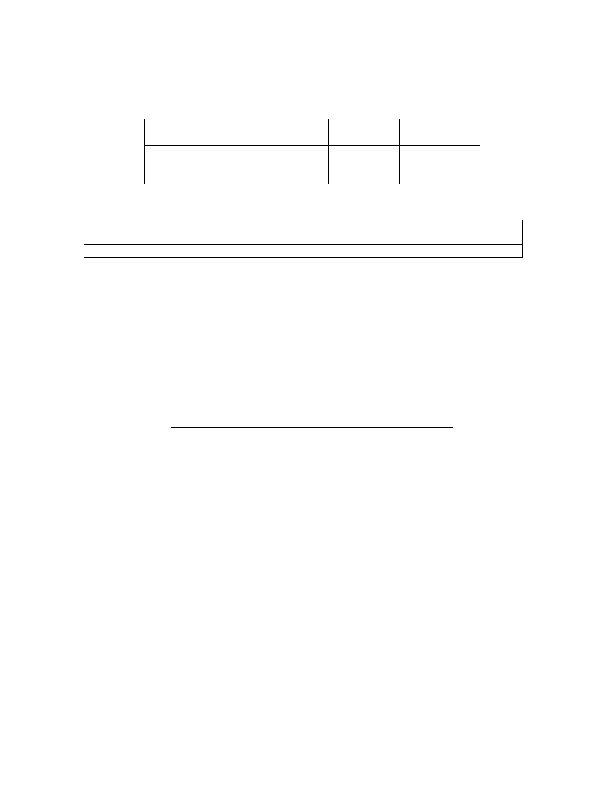
These capacities are for the standard cast iron and standard sheet metal sumps.
Engine type 2R1040 3R1040 4R1040/T/TA 6R1080/T/TA
Oil sump type S.M. S.M. S.M. S.M.
Initial fill
(lit.)
5.5 9 11.5 15
Refill (lit.) 4.5 7.5 9.5 13.5
Oil Specifications
Oil change period (Hours)
To be used for
MIL-L-2104 C PLUS
CF4, D4, D5
400 Naturally aspirated as well
as Turbo charged engines
The oil must be changed at least once in a year. This is applicable to the engines, which are
running for standby duty application.
The above oil change period is subject to following conditions.
•
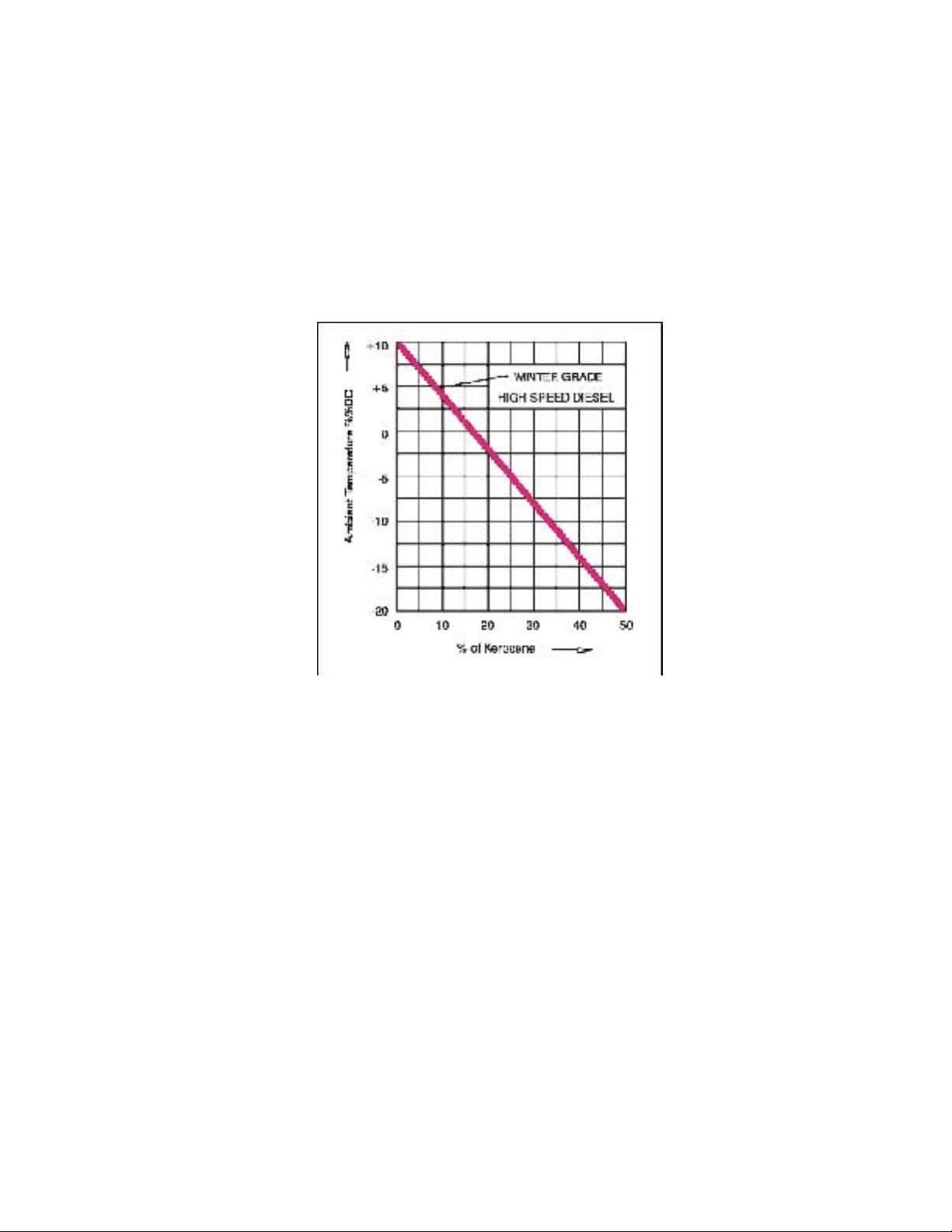
The minimum ambient temperature should not less than – 10
0
C.
Please contact your distributor for change in the ambient temp condition.
Note:
First fill = Sump capacity + Gallery capacity + Lube oil filter capacity
Fill the oil Lube oil filter before fitting on the engine.
Do not forget to fill the Lube oil filter whenever you replace the filter.
Whenever Lube oil filter is drained off, add approximately 0.5 lit. /1 lit.extra Lube oil
(as per the size of the Spin-on filter cartridge) in the sump to maintain the correct oil
level.)
The oil level in the sump should be checked at room temperature by using dipstick.
Top up with fresh oil when the level reaches the low level mark on dip stick, fill till it
increases to top level mark. Avoid over filling.
2.4.6 Lube oil Specifications and recommendations
The chart below shows the nomenclature of lube oil in different standards. Lube oils of
correct viscosity and detergency grades should be used. For detergency, oil should comply
with the following specifications
US Military
Specifications
American
Petroleum Institute
classification (API)
CCMC
MIL-2104C CD/SE -
MIL-2104C Plus
CF4 D4
For viscosity, the recommended SAE number should be used. SAE J 30 specifies the viscosity of
Lube oils for each SAE No.
Always use oil brands of reputed oil companies. Too viscous oil causes starting difficulties. The
ambient temperature prevailing at the time of starting the engine should be governed the choice of the
viscosity grade, during winter operation.

R1040 MAINTENANCE MANUAL
Page 9 of 48
It is recommended to use ‘multi grade oil’ considering the maximum and minimum ambient
temperatures.
No guarantee claims will be entertained on the grounds of engine damages due to use of unsuitable
engine Lube oils.
Atmospheric
Temperature range in C
Viscosity no
-20
0
to +20
0
SAE 10W30
-10
0
to +50
0
SAE 15W40
-5
0
to +45
0
SAE 20W40
Note:
The anticipated lowest temperature at the time of engine starting should be used as reference
in winter. While in summer the highest anticipated temperature of the day should be used as
reference.
2
.
5
Fuel supply system
2.5.1
F
uel
Circuit
Fuel is supplied to the block type fuel pump by a fuel lift pump (feed pump) incorporated in the
fuel pump itself. A dual type spin-on fuel filter consisting of efficient pre and micro paper
filter cartridges ensures the supply of clean fuel to the fuel pump. The schematic diagram (Fig.
2.5.1) shows the fuel circuit of the engine.
Fig. 2.5.1
NOTE:
It the fuel tank is to be installed below the fuel pump level, and then the bottom level
of the fuel tank should be less than 1 meter below the feed pump inlet
2.5.2
Fuel
Specifications
The performance of the engine depends upon
supply of clean and correct grade of
fuel. The fuel injection equipment is manufactured to very close tolerances and
slightest amount of dirt in fuel can cause wear on the injection equipment. Following
points are important in use of fuel on Kirloskar R1040/1080 series engines.
The following specifications are approved: -
•
BS: 2869-A1&A2
(In case of A2, note sulphur content)

R1040 MAINTENANCE MANUAL
Page 10 of 48
•
DIN 51 601
•
ASTMD 975-81:1D&2D
Winter
Grade
Fuel-
At low temperatures, waxing may occur and clog the fuel system, thus causing
operational troubles.
In the case of ambient temperature below 10° c, use ‘Winter Grade’ diesel fuel,
mixed with Kerosene.
Fig.2.5.2
Proportion of Kerosene to be mixed in Diesel, depends
on the ambient temperature
as shown in the graph (Fig.2.5.2). (Maximum proportion limited to 50%) For cold
starting aid see 3.4.1
PREPARE THE BLEND IN THE TANK ITSELF.
FILL IN THE NECESSARY AMOUNT
OF
KEROSENE FIRST, THEN ADD DIESEL FUEL.
2
.5.3
Storing
Fuel
Oil
The storage of fuel oil is of utmost importance since many engine problems are
traced to dirty fuel or fuel stored for too long a period. Store fuel in a
convenient place outside the building.
It is recommended that the fuel tank should be filled in at the end of the day’s
work. This keeps moisture
out of the tank.
To eliminate water from the fuel, drain out small quantity of fuel from fuel
tank through a drain plug every day before starting the engine.

R1040 MAINTENANCE MANUAL
Page 11 of 48
2.6 Cooling System
2.6.1 Radiator type cooling system
The Radiator type cooling system is used.
The Schematic diagram, of the typical water circuit with Radiator type cooling system, is
Shown in the Fig. 2.6.1 below.
Fig. 2.6.1
IMPORTANT
•
In order to have the efficient cooling and optimum performance of the engine, we
recommend using the radiator supplied by KOEL.
•
It is also necessary to ensure proper ventilation to avoid hot air re-circulation into the
cooling system. Please refer KOEL Genset Manual for details.
2.6.2 Coolant
In summer, use fresh water with anticorrosion additive for engine cooling to avoid rust
formation.
Water should be clear and free of any corrosive chemicals such as chloride, sulphates and
acids.
We recommend to use, coolant blend of soft water and one of the following rust preventive
compound as mentioned below
Nalco-2000 35 cc per liter.
In winter, use Ethylene glycol antifreeze diluted with coolant blend as mentioned above in
the proportion in the cooling system as mentioned below
Ambient
temperature
0
C
Ratio by volume of antifreeze
to cooling winter blend
+5 to –5 20:80
-6 to -15 33:67
-16 to -25 40:60
Below -25 50:50(Max. permissible ratio)

R1040 MAINTENANCE MANUAL
Page 12 of 48
Commercially available ready mixed coolants can
also be used, with Antifreeze
and anticorrosion additives after ascertaining suitability for low
ambient
temperature.
Storage of engine with only fresh water in engine
cooling system should be
avoided at ambient
temperature below 5° C. This may cause cracks
in the engine
components.
•
If the engine is to be transported from normal ambient areas to Low ambient areas
ambient
below +5°C the complete cooling system
should be drained and
refilled with Antifreeze + water mixture as mentioned above.
2.7 Electrical System
2.7.1 Electrical Equipment
Standard engines are equipped with 12V, negative earth electrical starting system
without battery and leads.
12 V Electrical system
Alternator
Make Specification Remarks
MICO 12V Common for 2 to 6
Cylinder engines
Starter
Make Specification Remarks
MICO 12V Common for 2 to 6
Cylinder engines
2.7.2 Battery
Battery Capacity Ratings
•
C.I.M (Compression ignition Motor) Rating -
Minimum current at 27° C
with full charged battery should sustain for 5 min. 30 sec with cell voltage of
1.33 V/cell
•
Cranking Performance Rating- It is a minimum
current in amperes which
fully charged battery at
27°C will sustain for a period of 2 minutes and
maintain cell voltage of 1.2V/cell or higher.
•
20 hours capacity rating-it is the capacity in ampere- hour, which the fully
charged battery will deliver when it is discharged at 27°C at a constant current
for 20 hour before reaching a final voltage over all
of 1.75 V/cell.
Recommended Battery Capacity
Ambient temperature
in
0
C
Battery Capacity in Amp-hr 20 hr rate
12 V 24V
Above + 10 135 Two Batteries of 12V, 88 Amp-hr. in series
Below +10 up to- 20 180 Two Batteries of 12V,120 Amp-hr. in series

R1040 MAINTENANCE MANUAL
Page 13 of 48
For battery capacity at extreme low temperature i.e. below -20°C, contact your
distributor.
Battery Cables setting Parameter
Cable drop should not exceed than 1.2 V at 600 A.
Normal starting current is 600A
Based on above two parameters, battery cables are recommended as below
Length in meter Core size in mm
2
Wire Specification
Up to 2.5 70 19/2.14 or 440/0.4
Up to 1.5 35 7/2.5 or 276/0.4
Up to 0.75 25 7/2.14 or 196/0.4
All above cable sizes are for copper cables and use of copper cables is
recommended.
The battery leads and terminals should be lead coated to avoid corrosion.
2.7.3 Engine wiring
Battery + ve and –ve connection, charging alternator +ve and –ve connections, starter
coil and pull coil connection should be wired/connected with 4 mm
2
wires. Since
current through these wire is 30 A. All other wires should be of 1.5 mm
2
minimum
due to mechanical strength consideration and not by electrical current capacity.
3Engine operation
3.1 Commissioning
Before you start a new or overhauled engine, attend following points
3.1.1 Oil
Fill the engine with Lube oil through oil filling neck as shown in fig. 3.1.1 below. For
oil quantity, grade and viscosity refer point no. 2.4.5 & 2.4.6 respectively.
Fig 3.1.1

R1040 MAINTENANCE MANUAL
Page 14 of 48
3.1.2 Diesel
Fill the fuel tank after making sure that it is properly clean. Use High Speed Diesel fuel
as recommended in section 2.5.2. According to the ambient temperatures, summer or
winter grade diesel fuel should be used. Connect the fuel pump to fuel supply tank as
shown in fuel circuit diagram fig. 2.5.1.
•
Never fill the fuel tank while the engine is running. Strictly observe cleanliness.
Do not spill any fuel.
•
The recommended minimum fuel pipe inside diameter for fuel inlet pipes & fuel
return pipe (leak off) between tank and engine are as below.
Fuel pipe Min. inside diameter mm
Fuel supply pipe between tank, engine &
filters
10 mm
Leak off return pipe from engine to tank 6 mm
3.1.3 Bleeding of fuel system
Loosen the vent screw on primary fuel filter as shown in fig.3.1.3.1 below
Fig.3.1.3.1 Primary element Fig. 3.1.3.2 Micro element
Operate the fuel lift pump (feed pump) until oil flows without air bubbles as
shown in fig. 3.1.3.3 below.
Fig. 3.1.3.3

R1040 MAINTENANCE MANUAL
Page 15 of 48
Tighten the vent screw on primary fuel filter while the diesel fuel id flowing
without air bubbles.
Similarly bleed the micro filter element by loosening the vent screw on it as
shown in fig. 3.1.3.2 above and tighten the vent screw after the removing the air
lock.
Loosen the banjo bolt on fuel pump gallery as shown in fig. 3.1.3.4 below.
Operate the fuel lift pump till the fuel flows free of air bubbles.
Fig. 3.1.3.4
3.1.4 Cooling system
Fill the cooling water system with recommended coolant blend (See section 2.6.2)
Fill the coolant through neck of radiator till it flows through the radiator over flow
pipe. (See fig. 3.1.4)
Fig. 3.1.4
Do not open the radiator cap while engine is running or hot. The cooling system is
under pressure hence danger of burning body skin.
Add coolant when the coolant system is cold. The temperature difference between
the coolant in the engine and the coolant being added must not exceed 50
0
C.
3.1.5 Belts
Check that belts are in position and the belt tension is proper. If the belt tension is not proper
adjust the same as described in section 5.5

R1040 MAINTENANCE MANUAL
Page 16 of 48
3.1.6 Valve Clearance
It is not necessary to check adjust the valve clearance on a new engine as it is already
adjusted at its required value. However after overhauling the engine, it is necessary to
recheck and adjust the valve clearance before starting the engine. See section 5.6.1
3.1.7 Other preparations
Check battery and lead connections. Also check the cable connections at the starter &
alternator. Loose connections lead to improper contact and damage to the terminals.
Remove lifting eyebolts after engine installation.
For trial run starting instructions, see section 3.2
After completing the preparations, run the engine for a short period of 10 minutes
without load.
-
Check the engine for oil and water leakages. If the leakages are noticed, remove
them.
After stopping the engine after the trial run check following.
-
With engine stationary, check the oil level. Top up the oil if necessary see section
5.1.2
-
Retighten the V belts, see section 5.5.1
3.2 Starting
3.2.1 Electric Starting
Before starting, make sure that no one is standing in the close vicinity of the engine
driven machine.
Open the ‘Shut off’ cock under fuel tank (if provided).
After repairs:
Make sure that all safety guards have been put back into their original position.
All tools are removed from the engine and the driven machine.
.
3.3 Engine stopping
Never stop the engine suddenly when running on load. First allow the engine to run on “NO”
load for 5 minutes and then stop the engine.
To stop the engine, follow the instructions as below.
Press the stop push button till the engine is completely stopped.
Charging current lamp lights up when engine has come to rest.
Turn the key counter clockwise to ‘OFF’ position and withdraw the key. The pilot
lamp will be goes off.
After stopping the engine, close the ‘Shut off’ cock under fuel tank (if provided)

R1040 MAINTENANCE MANUAL
Page 17 of 48
3.4 Operating conditions
3.4.1 Operation in winter
Lube oil viscosity
Select specified viscosity grade to meet the performance level for the ambient
temperature prevailing at the time of starting the engine. Refer section 2.4.6
Note shorter periods between oil changes when operating below –10
0
C. See section 5.1.1
Diesel fuel
Use winter grade fuel for operation below +10
0
C. See section 2.5.2.
Cold starting aids
Cold starting of a diesel engine depends upon the capacity of starter motor and that of the
battery. Since the starting equipment of the engine may differ according to its application,
please consult your dealer about the use of cold starting aid. However the general
guidelines are given below.
Temperature range Starting aid
Up to 0
0
C No cold starting aid is required.
0
0
to –20
0
C Use flame heater or start pilot
Below –20
0
C Consult your distributor
Battery
Cold starting requires a good state of charge of battery. Lowering the starting limit
temperature by 4
0
to 5
0
C is possible by increasing the battery temperature to about +20
0
C.
Removing the battery and storing it in a warm room or by using battery-preheating pads
could achieve this.
Engine coolant
Use coolant blend with antifreeze ‘Ethylene Glycol’ for operations below +5
0
C. The
percentage of mixing the antifreeze into water as per ambient temperatures is given in
section 2.6.2
High ambient temperature and/or High altitude
With increasing altitude or ambient temperature, the air density decreases, which affects,
1) Maximum power output of the engine.
2) The exhaust gas temperature.
3) In extreme cases the starting behavior.

R1040 MAINTENANCE MANUAL
Page 18 of 48
Note: -
The declared power ratings of the engine are obtained at standard reference
conditions as per ISO 3046/ BS 5514/ DIN 6271/ IS 10000.
Where engines are operated at greater altitudes and or higher ambient temperatures, they
must be derated in accordance with respective standards.
Deration Charts
Deration chart for Naturally aspirated engines
The deration chart applicable for naturally aspirated engines is illustrated below.
The chart is prepared on the basis of standard ambient conditions mentioned in ISO
3046/DIN 6271/BS 5514, with 60% relative humidity. For higher relative humidity the
deration increases by 2% for 20% rise in relative humidity above 60% relative humidity.
Deration chart for 4R1040T/6R1080T engines
The deration chart applicable for R1040T/6R1080T engines is illustrated below.

R1040 MAINTENANCE MANUAL
Page 19 of 48
Deration chart for 4R1040TA/6R1080TA engines
The deration chart applicable for 4R1040TA/6R1080TA engines is illustrated below
In case of doubt concerning such engine applications, contact your distributor.
3.5 Running in period
3.5.1 After first 100 hours running
•
Change engine oil and see 5.1.3
•
Change the Lube oil filter Cartridge/element see 5.1.4.
•
Check and retighten fasteners for Lube oil sump if necessary.
•
Clean the fuel strainer (button filter or sediment bowl at feed pump inlet) see 5.2.1
•
Clean and drain fuel filter bowl and change pre filter element/cartridge see 5.2.4
•
Check V belt tension and retighten if necessary see 5.5.1
•
Check engine for leakages of Lube oil, fuel, water.
•
Check the engine mounting bolts, retighten if necessary. See 5.8.3.
•
Retighten intake and exhaust manifold fastening at cylinder heads.

R1040 MAINTENANCE MANUAL
Page 20 of 48
4 Routine Maintenance
4.1 Maintenance Schedule
Every
10
th
Hour/
Daly
In running hours
1)
1st
50 100 250 400 500 800 1200 2400 3600
Check
Clean
Renew
Job
See
Secti-
on
Engine oil level
2
5.1.2
Fuel level in the tank
2
-
Coolant level in Radiator
2
5.3.1
Dry type air cleaner
3 4
5.4.1
Rubber hose & clips of dry type air
cleaner
-
Check the restriction indicator
5.4.1
Engine oil
5
5.1.1
&5.1.
3
Lube oil filter cartridge
5
5.1.4
Battery and lead connections
‘V’ Belt condition and tension
(adjust/replace if required)
5.5
Fuel Filter Cartridge (Pre)
4, 13
5.2.2
Radiator fins (depends on site
condition)
12
5.3.2
Radiator tubes (depends on type of
cooling water)
5.3.2
Fuel Filter Cartridge (micro)
4, 13
5.2.2
Thermostat element (change if
necessary)
5.3.3
Valve clearance (adjust if
necessary)
10
5.6.1
Starter/Alternator
5
5.7
Fasteners
10
5.8
Injector
10
-
Fuel tank
10
-
Exhaust silencer
3
-
Fuel Pump
11
-
Turbocharger
10
6.2
1) Maximum permissible
guide Intervals
2)
Top-up if required
3)
Clean if necessary
4)
Renew element/
Cartridge
5) Depends on engine use
6)
Depends on engine oil
change
7) Depends on rate of deposition
of scale.
8) 400 hours or at engine oil
change.
9) Whenever restriction
indicator indicates
10) Every six months or 1200
hours which is earlier.
11) FIP should be calibrated
after 3600 hours of engine
run.
12) Blow out dust
13) Refer point no 5.2.2 foot
note.
Other manuals for R1040
1
This manual suits for next models
6
Table of contents
Other KIRLOSKAR Engine manuals