De Havilland VAMPIRE User manual
Wingspan
Lenght
Weight
Wing Area
Radio Control
Duct Fan System
ESC
............................
.................................
.................................
...........................
......................
...................
.....................................
1407mm
1134mm
2600~2700g
(Battery excluded)
39.4dm2
6~7 Ch 12 Servos
90mm
80~110A
SPECIFCATIONS
RADIO CONTROLLED 90MM EDF SCALE AIRPLANE
ARF
VAMPIRE
IFYU.133

2
2
3
1
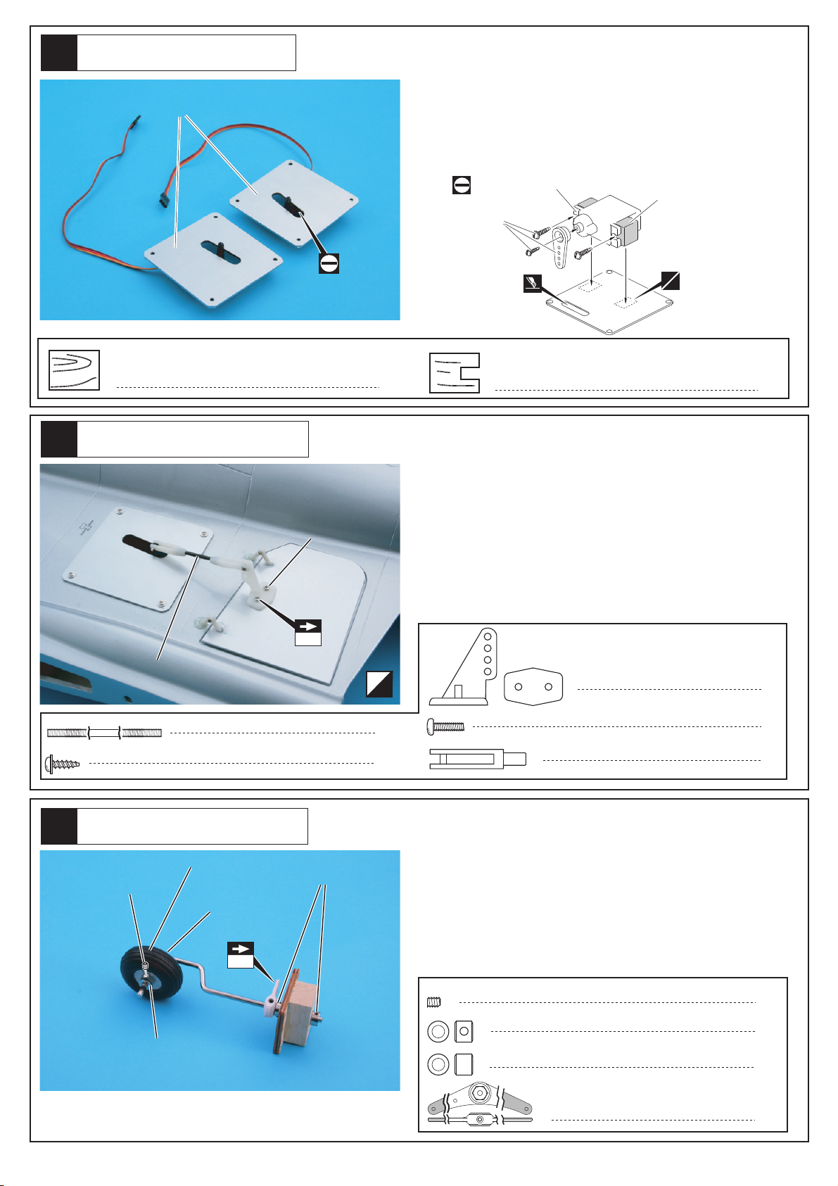
Assemble left and right sides
the same way. Must be purchased separately!
Cut off shaded portion.
Apply epoxy glue. Drill holes with the specified
diameter (here: 2mm).
Pay close attention here!
Apply instant glue (CA glue, super glue).
Ensure smooth non-binding
movement while assembling.
2mm
AB
LR
C.A
LR
Attach aileron with C/A glue and make sure aileron can
move upward and downward.
Attention: Make sure aileron is attached properly.
Main Wing
LR
C.A
C.A
6
Hard wood 12 x 12 x 6mm
24
2 x 8mm TP Screw
6
Hard wood 12 x 12 x 6mm
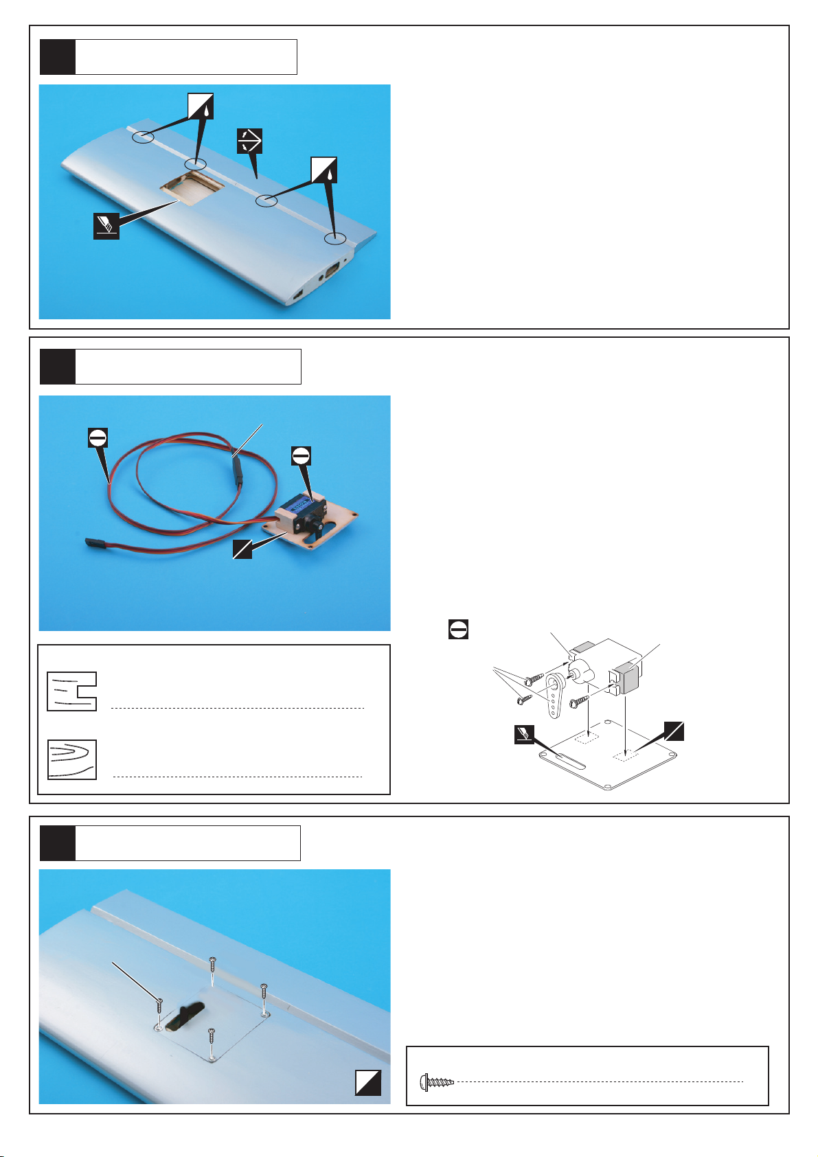
Aileron and Flap Servo
Assembly for (Micro) Servo
Must be purchased
separately!
Hard wood block
mount for servo.
lncluded with
the radio set.
AB
Flap
Aileron
Aileron and Flap Servo
Install aileron servo and flap servo on main wing as
shown in picture. Servo wire should go through from
the side of main wing. Then mount servos in place with
2x8mm TP Screws.
Attach the 12x12x6mm hard wood on servo tray with
A/B glue, then mount servo in place with the screws
supplied with servo.
Note the servo directions for left and right hand,
assemble left & right side the same way.
Note: Servo, servo plate & its parts are NOT included!

5
3
6
4
LR
LR
Drill two 2mm holes on where control horn will be
mounted as shown in picture.
Then put 2x12/16/20mm screws through control horn,
flap and aileron (as shown in picture). Then add the
horn base at the underside of flap and aileron, and
lock it in place. Then connect adjusters to both ends of
the 2mm threaded pushrod. Attach one end to control
horn, adjust to suitable length and then connect to
servo arm. Check the angle between servo arm and
pushrod. Assemble control horns on both sides for the
aileron and flap the same way.
4
2 x 20mm Screw
Rod adjuster
Horn
612
4
2 x 30mm Rod
2mm
2 x 12mm
Main Wing
2
2 x 60mm Rod
4
2 x 16mm Screw
4
2 x 12mm Screw
2
3 x 4 mm Set Screw
4.2mm Collar 2
75mm 75mm
8
2.6x 12mm TP Screw
Aileron and Flap
2 x 16mm
2 x 20mm
2 x 60mm Rod
2 x 30mm Rod
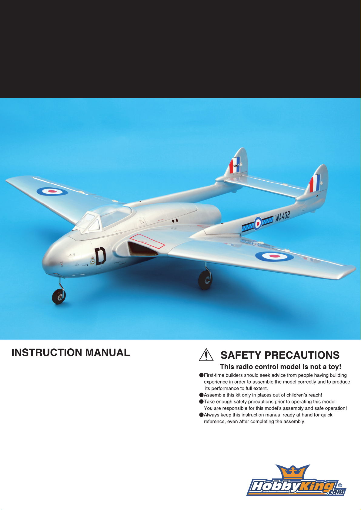
Fixed Landing Gear
2.6 x 12mm Screw
Cut away the covering and mount the fixed landing
gear on main wing with 2.6x12mm screws.
Insert 4mm wire to the wheel, then add the 4.2mm
collar and lock in place with the 3x4mm set screw.
Note: Skip to Step #7 if you are using retractable land-
ing gear.
8
4
9
7
LR
LR
8
2.6x 12mm TP Screw
14
2 x 8mm TP Screw
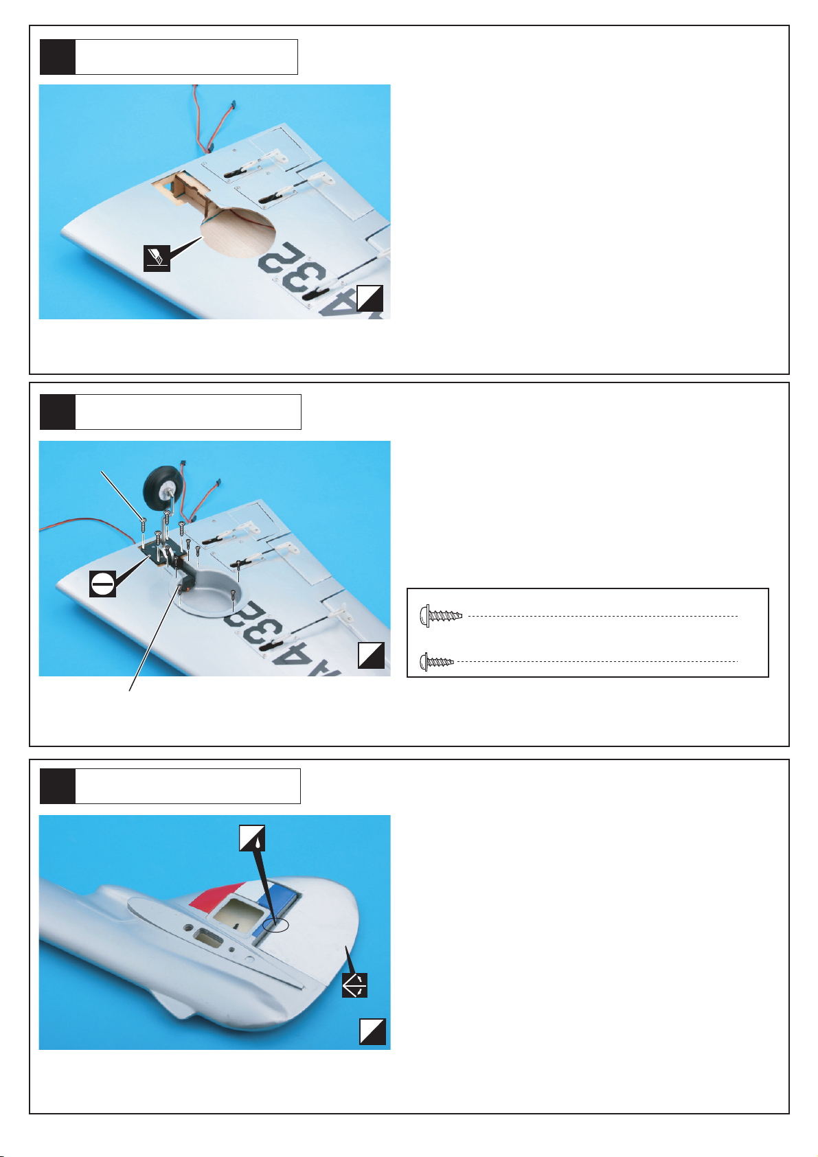
Mount the retractable landing gear on main wing with
four 2.6x12mm TP screws. Then put the PVC wheel
well in place with lock with 2x8mm TP screw.
Attention: Retractable landing gear and its parts are
NOT included.
Cut away the covering on where the retractable
landing gear will be mounted.
Attention: Not do cut too deep and weaken the balsa-
wood.
Retractable Landing Gear
Retractable Landing Gear
2.6 x 12mm Screw
2 x 8mm TP Screw
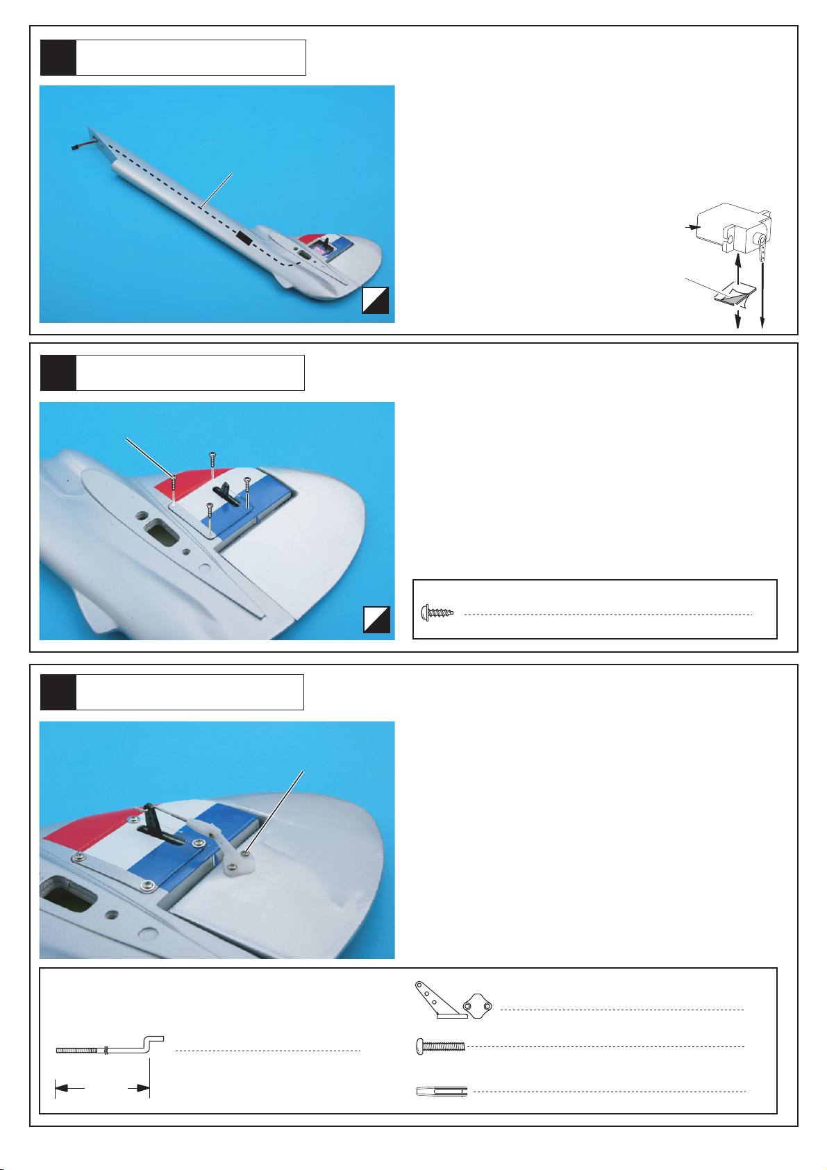
Rudder
Attach rudder with C/A glue and make sure rudder can
move smoothly.
Attention: Make sure rudder is attached properly.
LR
C.A
11
5
12
10
Rudder Servo
8
2 x 8mm Screw
2
NF: 1021 Clevis
4
2 x 16mm Screw
2
NF:1020 Control Horns
2
1.5 x 25mm Rod
25mm
LR
First, use a 400mm extension wire to connect to servo.
Then attach servo to vertical fin with strong double-
sided adhesive tape. Then put the wire through as
shown in picture.
You may also use A/B glue to attach the servo. But
please take into consideration for the quality of servo
and if it can be replaced or repaired easily.
Assemble left and right side the same way.
Attention: Double-sided adhesive tape and extension
wire are NOT included.
Double-Side Tape
Must be purchased
separately!
400mm extension
Place the PVC servo cover and lock with 2x8mm
screws as shown in picture.
Drill two 2mm holes on rudder on where control horn
will be mounted. Then put 2x16mm screw through
control horn and rudder, then add the horn base at the
underside of rudder and lock it in place. Then connect
the “Z” end of the pushrod to servo arm and connect
the other threaded end to clevis, adjust to suitable
length and attach to control horn.
Check the angle between servo arm and pushrod.
Assemble control horns on both sides of rudder the
same way.
Rudder Servo
Rudder Servo
2 x 8mm Screw
LR
2x16mm Screw
14
6
15
13
LR
C.A
C.A
4
2 x 8mm TP Screw
Cut away the covering on where servo will be
mounted. Then attach elevator to tailplane with C/A
glue and make sure elevator can move smoothly.
Attention; Make sure elevator is attached properly.
Tailplane
Elevator Servo
6
Hard wood 12 x 12 x 6mm
6
Hard wood 12 x 12 x 6mm
Must be purchased
separately! Hard wood block
mount for servo.
lncluded with
the radio set.
AB
approx. 600mm
AB
Elevator Servo
Put servo in place as shown in picture. The servo wire
will go through from the side of tailplane, and then lock
in place with 2x8mm screws.
2 x 8mm Screw
Assembly for (Micro) Servo
Connect extension wire (approx. 600mm) to servo.
Attach the 12x12x6mm hard wood on servo tray with
A/B glue, then mount servo in place with the screws
supplied with servo.
Note the servo directions for left and right hand.
Attention: Extension wire, servo, servo plate & its parts
are NOT included!

17
7
18
16
Tailplane
Tailplane
Flap
2
2 x 20mm Screw
Rod adjuster
Horn
12
1
2 x 30mm Rod
3 x 20mm Screw
3mm Washer
4
4
4
3mm No:1022
Drill two 2mm holes on where control horn will be
mounted as shown in picture. Then put 2x20mm screw
through control horn and elevator, then add the horn
base at the underside of elevator and lock it in place.
Then connect adjusters to both ends of the 2mm
threaded pushrod. Attach one end to control horn,
adjust to suitable length and attach the other end to
servo arm. Check the angle between servo arm and
pushrod.
2mm
2 x 20mm
2 x 30mm Rod
LR
First, put the servo wire through from the back of verti-
cal fin to the front, as shown in picture. Then insert
3x20mm screws at the side of fin, add 3mm washer
and lock tailplane in place.
3 x 20mm Screw
extension
AB
Attach 3mm hinge (#1022) in place with A/B glue, and
make sure flap can move smoothly
AB
20
8
21
19
Flap Servo
4
2 x 12mm Screw
Rod adjuster
Horn
2
4
2
2 x 60mm Rod
8
2 x 8mm TP Screw
NO:1006 (M4)
6
Hard wood 12 x 12 x 6mm
6
Hard wood 12 x 12 x 6mm
Must be purchased
separately! Hard wood block
mount for servo.
lncluded with
the radio set.
AB
Flap
Flap Servo
LR
Drill two 2mm holes on where control horn will be
mounted as shown in picture.
Then insert 2x12mm screws through control horn and
flap. Then add the horn base at the underside of flap,
and lock it in place. Then connect adjusters to both
ends of the 2mm threaded pushrod. Attach one end to
control horn, adjust to suitable length and then
connect to servo arm. Check the angle between servo
arm and pushrod. Assemble control horns on both
sides the same way.
2mm
2 x 12mm
2 x 60mm Rod
4
3 x 4 mm Set Screw
1
3
4.1mm Collar
Fixed Landing Gear
Insert M4 collar to the 4mm landing gear and insert to
the hard wood mount, adjust to suitable length and
lock in place with 3x4mm set screw.
Then attach the steering arm and lock it at suitable
direction with the 3x4mm set screw. Then drill a 2mm
hole on the steering arm.
Then insert 4mm nylon ring to the landing gear and
insert the 45mm wheel. Then add the M4 collar and
lock in place with set screw.
45mm
4mm Nylon Ring
1
4.1mm Collar
3 x 4 mm
2mm
4mm Nylon Ring
4.1mm Collar
Attention: Skip to Step#26 if you are using
retractable landing gear.
Assembly for (Micro) Servo
Attach the 12x12x6mm hard wood on servo tray with
A/B glue, then mount servo in place with the screws
supplied with servo.
Note the servo directions for left and right hand,
assemble left & right side the same way.
Note: Servo, servo plate & its parts are NOT included!

23
9
24
22
1
2 x 200mm Rod
1
3 x 4 mm Set Screw
Linkage Stopper
2mm Nut 1
1
4
2.6x 12mm TP Screw
Rod adjuster 1
2.6x 12mm TP Screw
Fixed Landing Gear
Mount the assembled nose steering landing gear on
fuselage with 2.6x12mm TP screws.
Nose Steering Servo
Must be purchased separately!
3 x 4mm
Linkage Stopper
Mount the linkage stopper on servo plate as shown in
below picture. Then mount servo on wood plate with
the screws supplied with servo.
Attach rod adjuster to the threaded end of the 200mm
rod, and connect to steering. Insert the other end with
the linkage stopper.
Attention: Servo, servo plate and its parts are NOT
included.
Nose Steering
Lock the 3x4mm set screw on linkage stopper in place
until the nose wheel is set at a suitable angle.

26
10
27
25
3 x 10mm
Aluminum tube
Collar
4
2 x 8mm TP Screw
4
2.6x 12mm TP Screw
4
0.4 x 500mm Wire
3 x 10mm Round brass tube
Rod adjuster 4
4
2 mm Rigging Couplers
1
2 x 8mm TP Screw
Nose Gear Cover
Drill a 5mm hole on nose gear cover and mount it in
place with 2x8mm TP screws.
5mm
Nose Retract
Mount nose retract in place with 2.6x12mm TP screws
as shown in picture.
Attention: Nose retract and it parts are NOT included.
2 x 8mm TP Screw
lncluded with
the radio set.
Steering Servo
Mount the nose steering servo in place with the screws
supplied with servo.
Insert the wire into the 3x10mm aluminum tube, add
the 2mm coupler and insert it back to the tube. Then
compress the tube so that the wire is tightened. Then
attach rod adjuster to coupler, adjust to suitable posi-
tion and connect to steering servo plate.
You may use shrinking rudder to wrap the wires for
better appearance.
Attention: Shrinking rubber, servo, servo plate and its
parts ARE NOT included.

29
11
30
28
3 x 10mm
Aluminum tube
Collar
Nose Steering
Nose Cover
4
2 x 8mm Screw
Aluminum tube
Insert the other end of the wire into 3x10mm aluminum
tube, then through the steering arm on front leg and
compress the tube so that the wire is tightened.
You may use shrinking rudder to wrap the wires for
better appearance.
Attention: Shrinking rubber is NOT included.
2 x 8mm TP Screw
Make cut-out on the cover for the nose steering, then
you can mount it on fuselage with 2x8mm TP screws.
Ducted Fan
Cut the exhaust pipe as shown in picture and mount
ESC in place with stripe
Attention: ESC and stripes are NOT included.


35
13
36
34
4 x 20mm Screw
4mm Washer
2
2
4
2 x 8mm TP Screw
AB
Tail Booms
Mount tail booms in place with two 4x20mm screws
and 4mm washers.
4 x 20mm Screw
4mm Washer
Canopy Cover
Place canopy cover on fuselage, then drill 1.2mm hole
on canopy and lock it in place with 2x8mm screws, as
shown in picture.
1.2mm
Attach canopy with canopy cover with A/B glue.
Canopy
1.2mm

14
37
12-18mm
12-18mm
0mm
64mm
65mm
C.G
AILERON
FLAP
RUDDER
ELEVATOR
15-25mm
15-25mm
0mm
12-18mm
12-18mm
0mm
15-40mm
0mm
Never fly before checking the C.G’s required position.
Control Surface Movement
This manual suits for next models
2
Popular Toy manuals by other brands

Primo Water
Primo Water 4-in-1 Potty instructions

Maxford USA
Maxford USA Albatros D.Va instruction manual

Reely Sky
Reely Sky EXTRA 300 operating instructions

Fisher-Price
Fisher-Price W9859 instruction sheet

Smoby
Smoby 330104 quick start guide

J-Power
J-Power Thunderbolt Mini A10 Assembly and operating instructions


