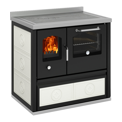
de manincor EKB110 User manual

INSTRUCTION MANUAL
THERMO-COOKER EKB110
1. OPERATION AND TECHNICAL CHARACTERISTICS
2. INSTALLATION GUIDE
3. ACTIVATION AND MAINTENANCE

For installation, maintenance and the warranty, see the THERMO-COOKERS and THERMO-
STOVES use and maintenance booklet supplied with thermo-cooker EKB110.
2.3 DESCRIPTION OF THERMO-COOKERS EKB110
a) radiant cast-iron hotplate
b) height-adjustable grill
c) oven with thermometer
d) oven light switch
e) starter for cold ignition of cooker
f) primary air thermostatic regulation
g) smoke path cleaning access
h) wood storage drawer
i) ash pan
j) boiler fittings
SUPPLIED ACCESSORIES
The following accessories are supplied with the
cooker:
k) scraper to clean the flue
l) stoker to move the rings
m) steel brush
n) oven grill and tray
o) oven mitt
p) grill crank
EKB110
1
b
j
i
f
g
h
d
c
e
a

1OPERATION AND TECHNICAL CHARACTERISTICS
The INTEGRATED OPEN TANK allows the separate operation of two circuits, primary (Thermo-
cooker) and secondary (Heating) by a coil heat exchanger with excellent heat transfer. The
thermo-cooker EKB110 can be equipped with a second exchange coil for domestic hot water
production.
1.1 OPERATION AND HYDRAULIC DIAGRAM
OPERATION
By means of the CTC control unit, when the Thermo-cooker reaches the temperature of
30°C (*), the Thermo-cooker pump switches on and then, at the temperature of 70°C
(*), the system pump turns on and the boiler turns off simultaneously. A third
temperature of 40°C (*), which can be set on the control unit, allows the deviation of
DHW production from the boiler to the thermo-cooker when the motorised VD diverter
valve trips.
(*) Preset default temperature value in the supplied control units which can be modified
by the user when installing and operating the system (see Control unit instructions,
pages 5-6).
2
RETURN
DELIVERY
DHW
CIRCUIT

THERMO-COOKER AND HEATING SYSTEM CIRCUITS PUMP 5.5 m wc
speed selector
3
Pumps with one inch fittings, three speeds, centre distance of 130 mm
Power absorbed by each pump: 55 W
3-way motorised diverter valve with fittings: G3/4"- male
Brazed stainless steel instantaneous coil heat exchangers
Galvanised sheet metal support plate 12/10
1.2 TECHNICAL CHARACTERISTICS
The parameters below (which can be modified by the user) indicate the temperature values of
the Thermo-cooker which, when reached, the Electronic control unit activates the various
components of the Hydraulic kit in sequence:
Thermo-cooker pump thermostat: 30°C Thermo-cooker circuit pump actuation (anti-
condensation function)
DHW valve thermostat: 40°C Diverter valve actuation for domestic hot water priority
Heating System pump thermostat: 70°C Heating system pump actuation and simultaneous
boiler switch-off.
Power supply: 230 Vac single phase
Maximum absorbed power: 76 W
Maximum operating pressure: 10 bar
Fluid temperature: +2 - 110°C
IN/OUT fittings: 1” GAS
Centre distance: 130 mm
Insulation class: IP 44
Material: Cast iron EN-GJL-150-200
Every year, before the start of the heating season,
unscrew and open the cap at the back of the pump,
being careful of squirting pressurised hot water,
manually turn the rotating part (using a
screwdriver) to unblock the rotor, if necessary
Supply Voltage: 230 Vac
Maximum operating temperature: 90 °C
Maximum operating pressure: 6 bar
Heating hydraulic connection: Ø 3/4"
Domestic Hot Water hydraulic connection: Ø1/2"
Thermo-cooker circuit IN/OUT temperatures: 80/64°C
Heating system IN/OUT temperatures: 55/69°C
HEADS WITH Q1= 1000 I / h
HEADS WITH Q2= 1400 I / h
speed 1
speed 2
speed 3
speed 1
speed 2
speed 3
H = 2.31 m wc
H = 3.62 m wc
H = 4.27 m wc
H = 1.60 m wc
H = 2.90 m wc
H = 3.80 m wc
H = 22.7 kPa
H = 35.5 kPa
H = 41.2 kPa
H = 15.7 kPa
H = 28.4 kPa
H = 37.3 kPa
HYDRAULIC PERFORMANCE CURVES
Head H ( m wc)
Head H ( kPa )
Flow rate Q ( I / h )

INPUTS
PROBE
Thermo-cooker Probe: Temperature Range 0 – 100 °C
FLUX
Flow switch/Boiler - DHW Thermostat ON/OFF Consent
LEV.
ON/OFF level switch
OUTPUTS
PUMP
System pump:
Power supply 230 Vac
Terminals 3(N) - 4(Fon)
VALV
Solenoid valve 2/3 wires:
Power supply 230 Vac
Terminals 5(N) - 6(Foff) - 7(Fon)
AUX
Auxiliary:
Potential-free contacts in exchange
Terminals 8(COM) - 9(N.C.) – 10(N.O.)
FDG ELECTRONIC CONTROL UNIT OPERATION
1. SWITCHING ON/OFF
The Control unit is switched on/off by holding down the button P1 (ON/OFF)
-The OFF status is signalled by the OFF LED lighting up
2. ALARM FUNCTION
If the temperature detected by the PROBE exceeds the alarm Thermostat value A01(90°C):
-the audible and visual warning device switches on
-SILENCE function: the buzzer can be switched off for 5 minutes by pressing any button
-when the 5 minutes have elapsed, if the alarm persists, the audible warning device goes off once again.
3. ANTI-FREEZE FUNCTION
If the temperature detected by the PROBE is below the Anti-freeze
Thermostat value A03 (6°C):
-the thermo-cooker PUMP switches on
-the display reads ICE
4. STANDBY FUNCTION
If the control unit is OFF in ALARM or ANTI-FREEZE condition:
-the control unit automatically switches to the ON status
TEMPERATURE PROBE
This measures and controls the water temperature in the
Thermo-cooker. It consists of a capsule Ø 6 x 30 mm in
Santoprene thermoplastic rubber and a cable diameter Ø 3.2
mm, length 2 m, bipolar (2 x 0.30 mm²).
There is an NTC 10 kΩ ± 1% at 25°C thermoresistive
sensor inside the capsule.
The temperature probe has a temperature range of
-50-120 °C, a response time of approximately 6 seconds,
electric insulation > 20 MΩ at 500 Vac, protection rating
IP68.
5. PUMP ANTI-BLOCK FUNCTION
If the PUMP remains idle for an amount of time longer than the
Anti-block Timer T01 (168 hours, equal to about one week):
-the PUMP switches on for T02 seconds (30 sec)
-the display reads bLP
This function is also activated in STANDBY
6. PUMP TEST FUNCTION
Holding down the button P3
-switches on the PUMP for the whole time the button is pressed
-the display reads tSt
7. LEVEL SWITCH FUNCTION
The level switch detects whether the water in the tank drops below the
minimum level:
-the LED lights up
8. OUTPUTS OPERATION
If the flow switch detects that domestic hot water is being drawn, the PUMP stops:
-the PUMP LED flashes and a flashing dash appears on the display.
It must be used inside a Ø1/2" probe
holder, supplied with control unit,
emerged in the delivery water of the
Thermo-cooker or Boiler. If needed, the
Probe-Hydraulic Kit connection can be
lengthened, to a Max of 15 m, using a
double-wire cable (2 x 0.50 mm²).
This function is not active if the probe temperature exceeds the value of the safety thermostat A02.
If the temperature of the probe exceeds the AUX thermostat value, the AUX output is activated.
If the temperature of the probe exceeds the VALV thermostat value, the VALV output is activated.
9. MAIN MENU
Setting of operating thermostats of controlled outputs:
-PUMP thermostat to control the operation of the system pump
4
FDG ADJUSTABLE 3-THERMOSTAT ELECTRONIC CONTROL UNIT
2 3 4 5 6 7 9 10 12
11
SENSITIVE
ELEMENT
LINE
PUMP
VALVE
AUX
LEV.
COM
N.C.
N.O.
PROBE
FLUX

-AUX thermostat for gas boiler integration, solenoid valve control or other application
-VALV thermostat to control diverter valve for domestic hot water
Simply clicking the button P1 (MENU) you may scroll the set Thermostat values, signalled by the flashing
associated PUMP / VALV / AUX LED
To change it, go to the thermostat value that needs to be modified:
-pressing button P2 increases the value
-pressing button P3 reduces the value
To save it, wait about 10 seconds or scroll all the parameters by pressing the (MENU) button
MAIN MENU PARAMETERS
MIN
DEFAULT
MAX
TYPICAL
VALUES
SET VALUES
Thermo-cooker PUMP thermostat
20
40
85
40
DHW VALVE thermostat
20
40
85
45
AUX thermostat
20
45
85
65
10. INSTALLER MENU (this menu must only be accessed by expert personnel, as changing these
parameters could make the product unsuitable for the application in use) To access the MENU
simultaneously hold down buttons P1 (MENU) and P4 ON/OFF for approximately 5 seconds
Press buttons P3 and P2 to scroll the labels of the parameters
Press P1 (MENU) to view the value of the parameter
To edit the value, press P3 and P2 while pressing P1(MENU)
To view the parameter list again and to store the value, press P1 (MENU)
Wait about 10 seconds to exit and save
MAIN MENU PARAMETERS
SYMBOL
MIN
DEFAULT
MAX
INSTALLED
VALUES
ALARM FUNCTION activation thermostat (°C)
A01
85
90
99
SAFETY thermostat (°C)
A02
20
85
90
“ICE" ANTI-FREEZE activation thermostat (°C)
A03
4
6
8
PUMP Thermostat Hysteresis (°C)
A04
1
4
10
Valve Thermostat Hysteresis (°C)
A05
1
2
10
AUX Thermostat Hysteresis (°C)
A06
1
2
10
ANTI-BLOCK Timer (h)
t 01
1
168
255
ANTI-BLOCK pump activation time (sec)
t 02
0
20
99
11. PROBE FAILURE ALERT
Flashing message LO (indicates out of scale towards low temperature below 0°C) = PROBE INTERRUPTED
Flashing message HI (indicates out of scale towards high temperature above 100°C) = PROBE SHORT-CIRCUITED
TECHNICAL CHARACTERISTICS
POWER SUPPLY: 230 Vac ± 10% ~ 50 Hz (protective fuse T3,15 A)
ABSORBED POWER: 2 Va ~
TEMPERATURE PROBE: In silicon/pvc cable
Operating temperature: -50 °C/ 130 °C
Measuring limits: 0-99 °C Precision: ± 1 °C
OUTPUTS: PUMP output powered 230 Vac max capacity 5 A 250 Vac
AUX output potential free contact max capacity 5 A 250 Vac
SERV output powered 230 Vac max capacity 5 A 250 Vac
MECHANICAL DIMENSIONS: Recessed temperature controller: 120x80x50 mm
Applied standards EN 60730-1 50081-1 EN 60730-1 A1 50081-2
5

The figure to the side shows the connections inside the
control unit, indicating the colours of the cables. You
can see that the terminals marked as FLUX are
jumpered: check for the presence of the above-
mentioned jumper, as without it the valve for DHW
production would be excluded.
These wiring diagrams must only be used by
qualified technical personnel.
2 INSTALLATION GUIDE
The appliance must be installed according to professional standard, following the instructions in this manual
and in compliance with the laws and regulations of each country, by QUALIFIED PERSONNEL acting
on behalf of Companies fit to assume full responsibility for the whole system.
Before putting the thermo-cooker into service, it is mandatory to set up the connections of the heating
system. Using the thermo-cooker with the boiler empty or not connected to the system would irreversibly
damage the boiler. In any case, the delivery connector, the return connector and the drain connector (to
empty the boiler in case of maintenance) must be connected to the system.
The tank of the thermo-cooker’s boiler must be filled manually, and topped up when notified by the specific
signal on the control unit.
2.1 HYDRAULIC CONNECTION
Pay special attention when setting up the hydraulic connection, not to force or twist the copper connections.
To counter the tightening torque exerted on the connection pipe flanged with the hydraulic system, use a
spanner or other tool on the nut of the pipe to be connected.
HYDRAULIC TESTING
When assembly operations are over, each Thermo-cooker is tested hydraulically with air at 6 bar, to make
sure that the different connections are perfectly airtight when pressurised.
After having transported/handled the thermo-cooker, tighten all the ring nuts of the copper pipes. They have
a diameter of Ø20 when used for heating and Ø14 for domestic hot water production. It is recommended to
install manual outlet shut-off valves, to facilitate maintenance: valves with GAS 3/4" male-female couplings
for heating and GAS 1/2" for domestic hot water production.
HYDRAULIC CONNECTION
Set up the hydraulic connection according to the diagram on page 2 of this manual. It is recommended to
install shut-off valves.
2.2 ELECTRICAL CONNECTION
Before setting up the electrical connection, make sure
the mains power is disconnected.
Connect the power line to a two-pole switch complete with
fuses (power supply 230 Vac: 50Hz), including the
essential and correct connection to the earthing system.
The Thermo-cooker must be powered by a line with a
residual current device upstream, as set forth by current
standards. Correct operation of the control relays is only
guaranteed for pump and valve motors with load up to
100W. The manufacturer will not be held liable for
improper use.
ELECTRICAL TESTING
Each HYDRAULIC KIT is tested electrically by connecting the
control unit to a control board, where the different possible
temperatures in the thermo-cooker are simulated in sequence,
from the anti-freeze function to the maximum temperature safety
function A02 at 99°C.
6

3 ACTIVATION AND MAINTENANCE
Before installing the thermo-cooker, you must wash the pipes of the system it is connected to. The thermo-cooker
could malfunction if the pipes are dirty inside.
When the hydraulic installation and electric wiring have been set up, fill the system of the Thermo-cooker and of the
Heating system with water.
ATTENTION. Running the pump without first completely eliminating any air inside would burn the motor due
to overheating. Heat the probe with a lighter or hairdryer to start the pump. Make sure there are no water leaks when
the system is pressurised.
We remind you that the circulation pump has 3 rotation speeds, to be adjusted manually depending on the features of
the system and on the flow rate/head technical data expected by the design engineer.
The speed is set at 2 when the appliance leaves the factory.
Maintenance must be assigned to qualified personnel working in compliance with standards in force and according to
the instructions in this booklet. Before starting any maintenance operation, make sure that the mains power is
disconnected. Before performing any extraordinary maintenance which entails disassembly, make sure to have
closed the shut-off valves on the Thermo-cooker’s external piping.
PROBLEM
CAUSE
SOLUTION
The thermo-cooker quickly reaches
operating temperature (70 - 80 °C) while
the heating system (radiators) stays cold
Air pockets in the secondary
heating circuit
Carefully vent the entire heating system and
bring the pressure of the closed tank part to a
value suitable for the height of the system.
The thermo-cooker quickly reaches
operating temperature (70 - 80 °C) while
the heating system (radiators) stays cold
The circulation pumps do not work
Check that the electrical connections of the
pumps and of the control unit are intact and
efficient
The control unit indicates LO
Probe defect.
Ambient temperature lower
than zero.
Risk of freezing
Check that the probe is well-connected to the relative
terminals of the control unit. If LO is still displayed,
make sure the probe is not interrupted or blown
The control unit indicates Hl
Probe short-circuited.
Temperature of the thermo-
cooker
>100°C
The Thermo-cooker is in overtemperature,
immediately reduce the fire, open the door to cool
the combustion chamber and make sure the
system is vented. If the Thermo-cooker is not on,
use a Tester to check whether the resistance of
the probe is at zero
Domestic hot water is not produced
Malfunction of the motorised
diverter valve
Check that the valve temperature set on the
control unit is not too high; check the position of
the 3-way valve control rod.
As per the figure on page 4
The control unit does not switch on
Power failure
Check that there is a voltage of 230 Vac in the
power line and at the relative terminals of the
control unit. Check the fuse inside the control unit
.
7
Table of contents
Other de manincor Cooker manuals
Popular Cooker manuals by other brands
Garwoods
Garwoods EC-2072 Installation & operating instructions
Zanussi
Zanussi ZCV667MWC user manual

Electrolux
Electrolux ETG729GKT installation instructions
VOX electronics
VOX electronics GHT631 operating instructions

Tricity Bendix
Tricity Bendix SI360 OPERATING AND INSTALLATION Manual
Bosch
Bosch HSB738257 M instruction manual


