De Nora NXT3000 Series Training manual
- 1 - 100.6702.6
Instruction Bulletin - Series NXT3000
Meter Assembly,
1-500 PPD (10 kg/h) Maximum
1 - 500 PPD (2 - 10 kg/h) Maximum

100.6702.6 - 2 -
These instructions describe the installation, operation and maintenance of the subject equipment. Failure to strictly
follow these instructions can lead to an equipment rupture that may cause significant property damage, severe
per-sonal injury and even death. If you do not understand these instructions, please call DeNoraWaterTechnologiesfor clarification before commencing any work at +1 215-997-4000 and ask for a Field Service
Manager. DeNoraWaterTechnologies, Inc. reserves the rights to make engineering refinements that may not be
described herein. It is the responsibility of the installer to contact DeNoraWaterTechnologies, Inc. for information
that cannot be answered specifically by these instructions.
Any customer request to alter or reduce the design safeguards incorporated into DeNoraWaterTechnologiesequipment is conditioned on the customer absolving DeNoraWaterTechnologiesfrom any consequences of
such a decision.
DeNoraWaterTechnologieshas developed the recommended installation, operating and maintenance procedures
with careful attention to safety. In addition to instruction/operating manuals, all instructions given on labels or
attached tags should be followed. Regardless of these efforts, it is not possible to eliminate all hazards from the
equipment or foresee every possible hazard that may occur. It is the responsibility of the installer to ensure that the
recommended installation instructions are followed. It is the responsibility of the user to ensure that the
recommended operating and maintenance instructions are followed. DeNoraWaterTechnologies, Inc. cannot be
responsible deviations from the recommended instructions that may result in a hazardous or unsafe condition.
DeNoraWaterTechnologies, Inc. cannot be responsible for the overall system design of which our equipment may
be an integral part of or any unauthorized modifications to the equipment made by any party other that DeNoraWaterTechnologies, Inc.
DeNoraWaterTechnologies, Inc. takes all reasonable precautions in packaging the equipment to prevent shipping
damage. Carefully inspect each item and report damages immediately to the shipping agent involved for
equipment shipped “F.O.B. Colmar” or to DeNoraWaterTechnologiesfor equipment shipped “F.O.B Jobsite”. Do
not install damaged equipment.
DENORAWATERTECHNOLOGIES,INC.COLMAR OPERATIONS
COLMAR, PENNSYLVANIA, USA
IS ISO 9001: 2008 CERTIFIED

- 3 - 100.6702.6
Table of Contents
1INTRODUCTION ................................................................................................................................................. 4
1.1 General ...................................................................................................................................................... 4
1.2 Warranty and Service ................................................................................................................................ 4
1.3 Meter Assembly Data ................................................................................................................................. 4
1.4 Multiple Meter Assemblies ......................................................................................................................... 4
2OPERATION ....................................................................................................................................................... 5
2.1 General ....................................................................................................................................................... 5
2.2 Installation................................................................................................................................................... 5
3START-UP .......................................................................................................................................................... 10
4SERVICE ........................................................................................................................................................... 10
5TROUBLESHOOTING CHART ......................................................................................................................... 11
FIGURES
1Basic System Schematic ...................................................................................................................................... 6
2Basic Assembly Procedures ................................................................................................................................ 7
3Multiple Meter Assembly ...................................................................................................................................... 8
4 Meter Assembly Dimensions ................................................................................................................................ 9
100.6702.6 - 4 -
1INTRODUCTION
1.1 General
The Capital Controls meter assemblies are expertly engineered and carefully tested to assure years of
satisfactory operation. The meter assemblies may be mounted directly on the vacuum regulator or remotely
mounted. Proper installation and care will ensure the best operation. Read instructions carefully and retain
for future reference.
These instructions cover Series NXT3000 Meter assemblies only. Refer to the following for other components
in the gas feed system.
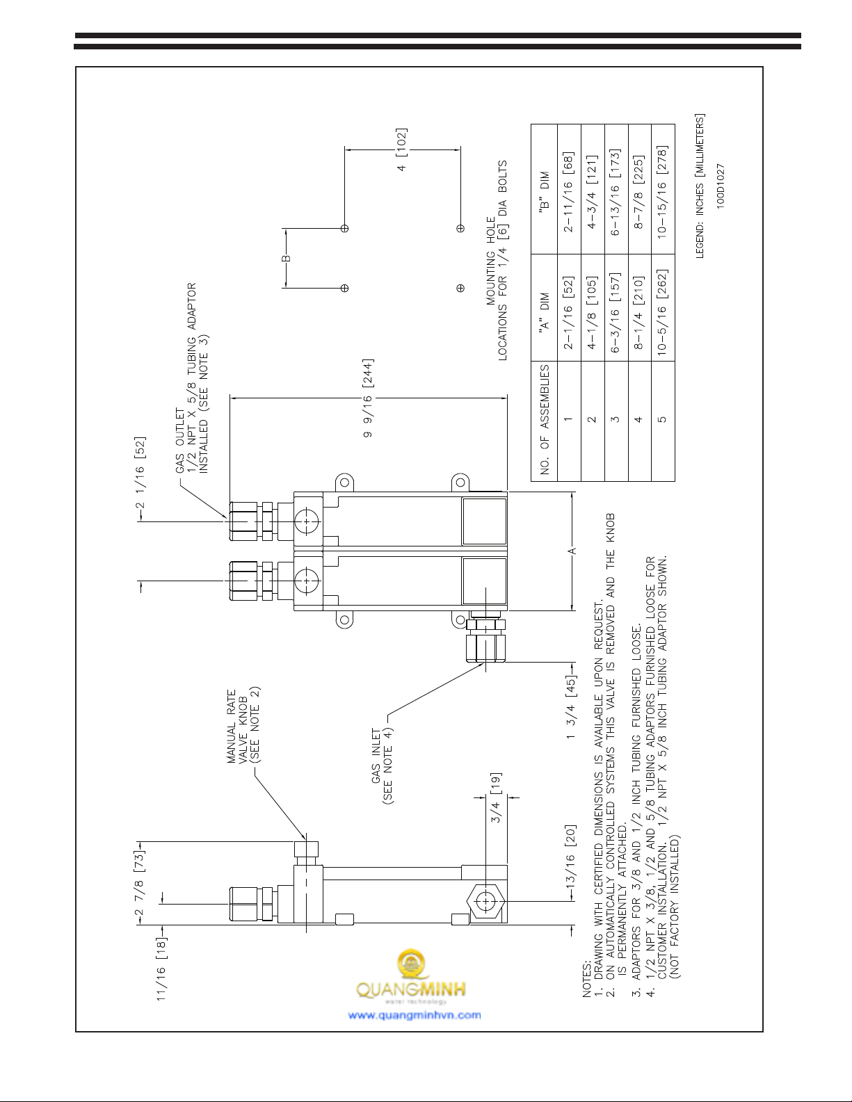
Meter Assembly Dimensions - 100D1027
Vacuum regulator -100.6701
Ejector - 122.6060
1.2 Warranty and Service
See 005.9001 for Capital Controls equipment warranty.
NOTE: The Series NXT3000 Meter Assembly is designed for use with a Series NXT3000 gas feeder. The
Capital Controls equipment warranty and service policy is null and void, as it pertains to user protection, if
the Series NXT3000 Meter Assembly is misapplied.
1.3 Meter Assembly Data
Meter tube scale length: 4"
Each meter assembly is furnished with 3/8", 1/2" and 5/8" tubing fittings. Refer to the capacity chart below
for recommended minimum tubing sizes to be used with each capacity. Tubing sizes may have to be
increased for long vacuum line runs. Refer to Bulletin 121.3003.
Capacities Available for Chlorine,
Sulfur Dioxide and Carbon Dioxide* Minimum Inlet & Outlet Tubing Connection sizes
1, 3, 10, 25, 50, 100 PPD
(20, 60, 200, 500 g/h, 1, 2 kg/h) 3/8"
200 PPD
(4 kg/h) 1/2"
300, 500 PPD
(5, 10 kg/h) 5/8"
Capacities Available for Ammonia Minimum Inlet & Outlet Tubing Connection sizes
5, 10, 25, 50, 100 PPD
(30, 100, 250, 500 g/h, 1 kg/h) 3/8"
100 PPD
(2 kg/h) 1/2"
250 PPD
(5, 10 kg/h) 5/8"
When ganged meter assemblies are used, determine the proper tubing size by adding together all the
meter capacities in the final assembly and refer to the chart above.
1.4 Multiple Meter Assemblies
Multiple Meter Assemblies may be made up by connecting up to five (5) individual meter assemblies into
one unit for multiple feed points.
*Carbon dioxdie service uses a chlorine tube with a factor x 0.75.

- 5 - 100.6702.6
2OPERATION
2.1 General
The meter assembly is designed to complement the Capital Controls’ Series NXT3000 vacuum regulators.
The meter assembly is a variable area type meter and provides visual indication of the gas flow rate set by
the internally mounted manual rate valve.
The rate valve is located at the meter outlet (top) and is sized to match the meter capacity.
The capacity range of each flowmeter-rate valve assembly is clearly indicated by a calibrated scale, direct
reading in pounds per day (lb/d) and grams per hour (g/h) or kilograms per hour (kg/h), etched on the
flowmeter tube.
The meter assembly on a gas feed system with an automatic Chloromatic rate valve assembly will have the
rate valve knob glued in place on the outlet fitting.
NOTE: When two meter assemblies will be used in series, (one mounted on the vacuum regulator and one
remote mounted) one of the meter assemblies must be supplied as an automatic unit, without rate valve.
The second meter assembly will be supplied as a manual unit with rate valve.
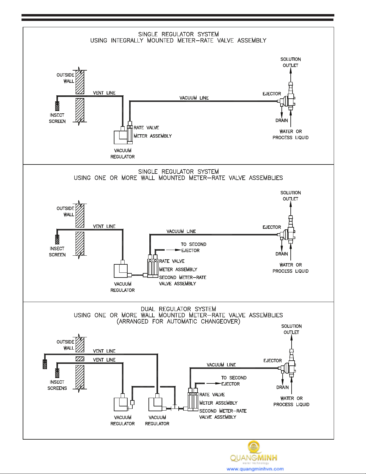
2.2 Installation - See Figures 1, 2, 3 and 4
The meter assembly must be installed in an upright and level position in order to function properly.
Each meter assembly comes complete with the necessary o-ring seals, mounting feet and tubing fittings to
accommodate either mounting directly on a vacuum regulator or a wall. The parts supplied will allow the
meter assemblies to be ganged together to form a multipoint meter assembly of up to five (5) units. Tubing
connectors are also provided to allow using interconnecting tubing sizes of 3/8", 1/2" or 5/8".
For a manually controlled system the meter assembly is installed between the vacuum regulator and the
ejector. For an automatically controlled system the meter assembly is installed between the automatic
control valve and the vacuum regulator. Mount the meter panel using suitable screws, bolts and anchors
appropriate for the mounting surface.
When the meter assembly is to be mounted on a wall, locate if so that it is upright on a vertical surface
convenient for observation and operation.
Black polyethylene tubing is normally used for the vacuum line. Do not kink this tubing. It may be desirable to
use tubing connectors, tees or elbows to provide as direct run as possible and minimize kinking conditions.
Use enough tubing length to allow movement of the vacuum regulator for servicing or cylinder change.
When attaching tubing to the tubing fittings, tighten the connector nut HAND TIGHT.
General Design Note: Routing vacuum tubing through unventilated conduit is discouraged. A minute portion
of gas flowing through tubing under vacuum conditions, will slowly diffuse at a molecular level through its
walls and collect in the closed conduit over and extended period of time.
100.6702.6 - 6 -
Figure 1 - Basic System Schematics

- 7 - 100.6702.6
Figure 2 - Basic Assembly Procedures
INTEGRAL MOUNTING
METER ASSEMBLY ON VACUUM REGULATOR
Seat the seal O-ring in the outer counterbore of the gas outlet con-
nection of the vacuum regulator. Then mount the flowmeter-rate valve
assembly on the side of the regulator as indicated.
Set aside the mounting plates and adaptor fittings (loose packaged to
permit for optional wall mounting) which are not needed in this applica-
tion.
PREPARING METER ASSEMBLY
FOR WALL MOUNTING
Install the mounting plates on the rear of the meter assembly as indi-
cated. Then install the adaptor fitting(s), as required, in the gas outlet
connection of the vacuum regulator(s).
If only one flowmeter-rate valve assembly is used, install the adaptor
fitting, as indicated, in the gas inlet connection of this component. Then
mount as described in Figure 5 and complete the interconnections as
shown in Figure 1. Or, if two or more meter assemblies are used, pro-
ceed as directed in Figure 3.

100.6702.6 - 8 -
Figure 3 - Multiple Meter Assembly
Seat the seal o-ring in the outer counterbore of the of the gas outlet connector on the flow
meter. Then mount the adjacent flow meter assembly. Do not seat the o-ring on the protu-
sion of the adjacent flow meter assembly.
Assemble the meter-rate valve assemblies and install the adaptor fitting as indicated.
Then mount as described in Figure 4 and complete the interconnections as shown in
Figure 1.
- 9 - 100.6702.6
Figure 4 - Meter Assembly Dimensions

100.6702.6 - 10 -
4SERVICE
It is recommended that the Gas Dispensing System be inspected regularly and serviced at least once per
year. Depending on usage, operating procedures, gas flowrate and or/gas quality the period between
scheduled maintenance may have to be shortened. Operation experience will dictate the period needed to
suit the particular site conditions.
Preventative maintenance kits are available from the factory. Each kit contains all the parts and detailed
instructions that are required for complete maintenance. All resilient parts (O-rings, gaskets) that have been
distributed during disassembly must be replaced during reassembly in order to insure safe, trouble free
operation. Failure to replace these parts may result in bodily injury.
Preventative Maintenance Kit for chlorine and sulfur dioxide P/N 614S096U01.
For detailed component breakdown, refer to parts list 100.7602.
3START-UP
Follow the instructions provided in the NXT3000 vacuum regulator instruction manual 100.6701 for complete
system start-up procedures.
After the system has been tested for leaks and is operating, adjust the rate valve to the desired gas flow rate.
The flow rates are in PPD (pounds per day or kg/h as applicable) of chlorine.
Read the flowmeter scale at the center of the ball.
NOTE: NEVER use the rate valve on the remote meter panel to shut off the gas supply. This valve is for
adjusting flow rate while the system is in operation. If used for shut-off, this valve will be damaged. To shut
off the gas, close the gas container valve.

- 11 - 100.6702.6
5TROUBLESHOOTING CHART
Since the operating performance of the meter assembly can be effected by the vacuum regulator and
ejector, also refer to the Troubleshooting Chart in bulletin 100.6701 and 122.6060.
TROUBLE PROBABLE CAUSE CORRECTIVE ACTION
1. The required gas feed rate
is not achieved at start-up.
a. Insufficient ejector vacuum due to
insufficient water supply pressure
for existing back pressure
conditions.
b. Leakage at vacuum line
connections, vacuum regulator
and/or inlet to ejector.
c. Vacuum line(s) crimped.
d. Length of vacuum line(s) exceeds
maximum allowable transport
distance.
a. Refer to Trouble 2.
b. Inspect each connection and
remake as necessary.
c. Replace vacuum tubing and
arrange line(s) to eliminate
d. Refer to Bulletin 121.3003.
2. Flowmeter ball bounces and/
or maximum gas feed rate
cannot be achieved during
normal operation.
a. Vacuum regulator inlet filter screen
dirty.
b. Rate valve dirty.
c. Flowmeter dirty.
d. Ejector water supply pressure
fluctuating causing insufficient
ejector vacuum. (Ball bouncing
only)
a. Replace gas inlet filter.
b. Clean the rate valve. See Service
section.
c. Clean the flowmeter. See Service
section.
d. Check water supply pressure.
Correct as necessary
3. Flooded metering tube. a. Dirt on the ejector check valve seat,
or worn seat
a. Clean or replace ejector check
valve seat. Refer to Ejector
instruction manual 122.6006,
122.6010, 122.6015, or 122.6060.
4. Vacuum leaks a. Rate valve o-rings worn.
b. Tubing connector loose.
c. Cracks in tubing
a. Replace o-ring.
b. Tighten tubing connector.
c. Replace tubing.

100.6702.6 - 12 -
Represented by:
Design improvements may be made without notice. DeNoraWaterTechnologies3000AdvanceLaneColmar,PA18915ph+12159974000•fax+12159974062web:www.denora.commail:[email protected]®RegisteredTrademark.©2015.AllRightsReserved.SEP2015
Table of contents
Other De Nora Measuring Instrument manuals


