De Nora 200 Series User manual
- 1 - 100.6015.10
Instruction Manual — Series 200
Remote Meter Panels 500 PPD
(10 kg/h) Maximum Capacity
100 PPD (2 kg/h) Maximum 200 PPD (4 kg/h) Maximum
(250 PPD [5 kg/h] Chlorine only)
500 PPD (10 kg/h) Maximum

100.6015.10 - 2 -
These instructions describe the installation, operation and maintenance ofthe subject equipment. Failure to strictly
follow these instructions can lead to an equipment rupture that may cause significant property damage, severe
per-sonal injury and even death. If you do not understand these instructions, please call De Nora Water
Technologies for clarification before commencing any work at 215-997-4000 and ask for a Field Service Manager.
De Nora Water Technologies, Inc. reserves the rights to make engineering refinements that may not be
described herein. It is the responsibility of the installer to contact De Nora Water Technologies, Inc. for
information that cannot be answered specifically by these instructions.
Any customer request to alter or reduce the design safeguards incorporated into De Nora Water Technologies
equipment is conditioned on the customer absolving De Nora Water Technologies from any consequences of
such a decision.
De Nora Water Technologies has developed the recommended installation, operating and maintenance procedures
with careful attention to safety. In addition to instruction/operating manuals, all instructions given on labels or
attached tags should be followed. Regardless of these efforts, it is not possible to eliminate all hazards from the
equipment or foresee every possible hazard that may occur. It is the responsibility ofthe installer to ensure that the
recommended installation instructions are followed. It is the responsibility of the user to ensure that the
recommended operating and maintenance instructions are followed. De Nora Water Technologies, Inc. cannot be
responsible deviations from the recommended instructions that may result in a hazardous or unsafe condition.
De Nora Water Technologies, Inc. cannot be responsible for the overall system design ofwhich our equipment may
be an integral part of or any unauthorized modifications to the equipment made by any party other that De Nora
Water Technologies, Inc.
De Nora Water Technologies, Inc. takes all reasonable precautions in packaging the equipment to prevent shipping
damage. Carefully inspect each item and report damages immediately to the shipping agent involved for
equipment shipped “F.O.B. Colmar” or to De Nora Water Technologies for equipment shipped “F.O.B Jobsite”. Do
not install damaged equipment.
De Nora Water Technologies, COLMAR OPERATIONS
COLMAR, PENNSYLVANIA, USA
IS ISO 9001: 2008 CERTIFIED

- 3 - 100.6015.10
Table of Contents
1 INTRODUCTION ..........................................................................4
1.1 General ...........................................................................4
1.2 Warranty and Service................................................................ 4
1.3 Remote Meter Panel Data .............................................................4
2 OPERATION .............................................................................5
2.1 General ...........................................................................5
2.2 Installation .........................................................................5
3 START-UP ...............................................................................8
4 SERVICE ...............................................................................12
4.1 Cleaning the Flowmeter Assembly......................................................12
4.2 Rate Adjustment Valve Cleaning .......................................................12
5 TROUBLESHOOTING CHART ..............................................................13
FIGURES
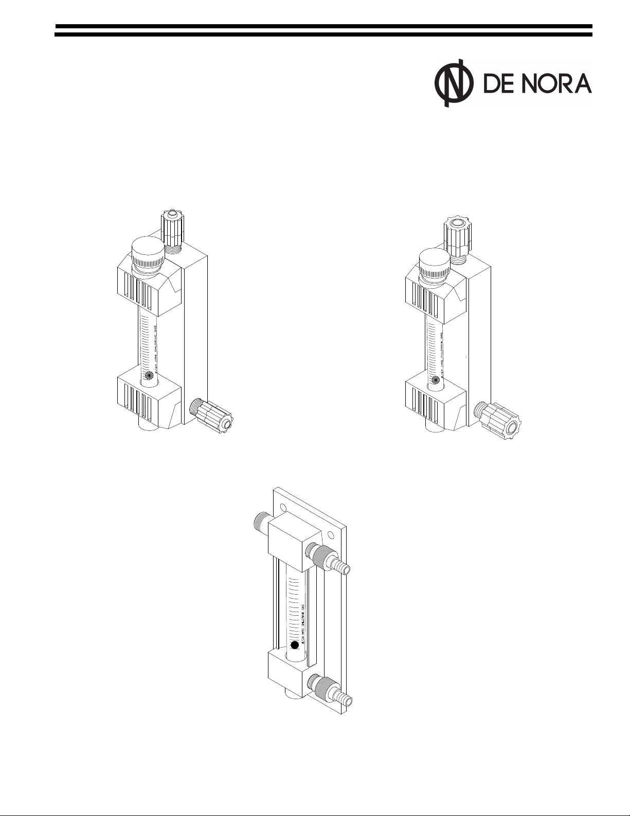
1 100 PPD (2 kg/h) Meter Panel ..........................................................6
2 200 PPD (4 kg/h) (250 PPD/5 kg/h Chlorine only) Meter Panel .................................7
3 500 PPD (10 kg/h) Meter Panel .........................................................8
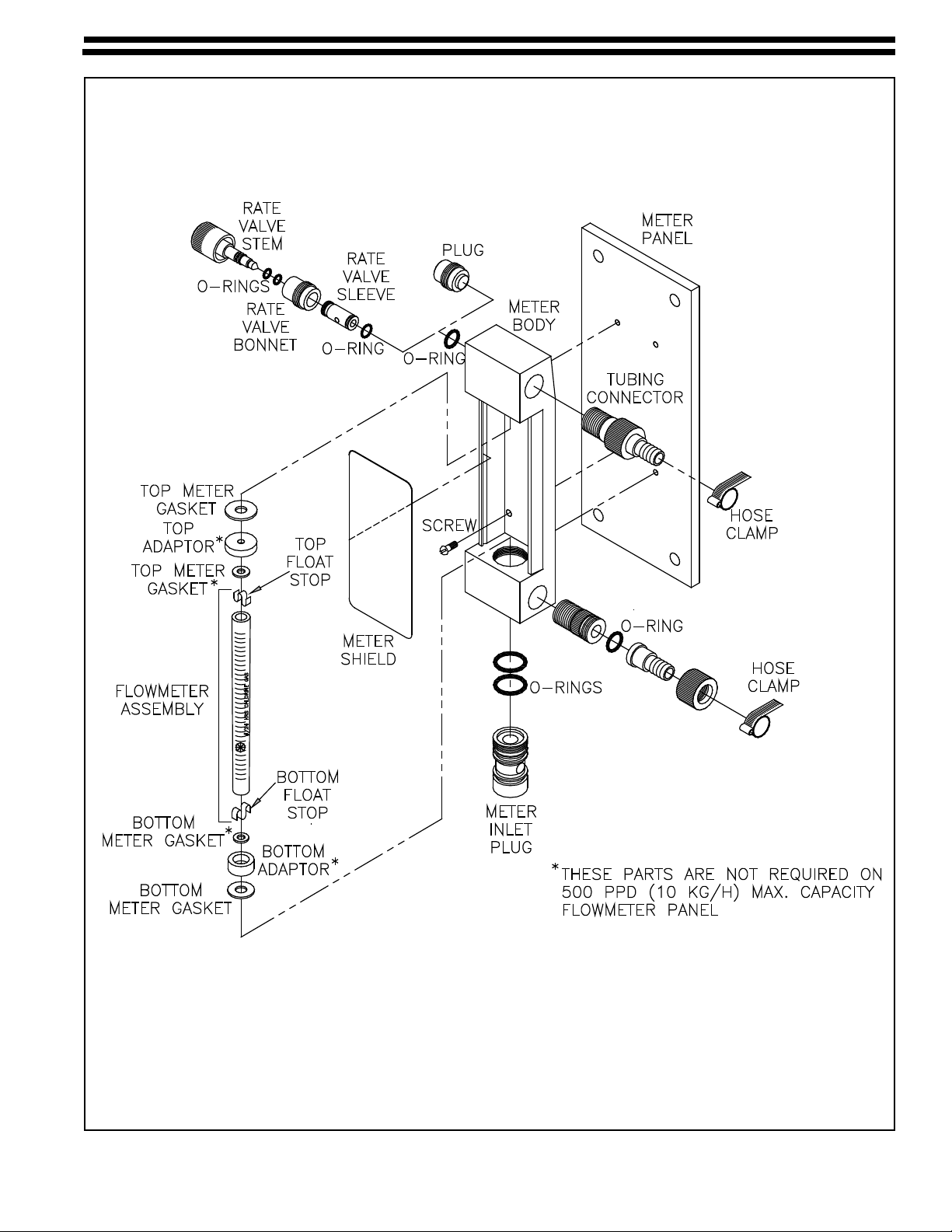
4 100 PPD (2 kg/h) Meter Panel Components ...............................................9
5 250 PPD Max (4 kg/h) Meter Panel Components...........................................10
6 500 PPD (10 kg/h) Meter Panel Components .............................................11

100.6015.10 - 4 -
1 INTRODUCTION
1.1 General
The ADVANCE®remote meter panels are expertly engineered and carefully tested to assure years of
satisfactory operation. The meter panels are constructed of the finest materials available for gas service.
Proper installation and care will ensure the best operation. Read instructions carefully and retain for future
reference.
These instructions cover Series 200 Remote Meter panels only. Refer to the following for other components:
Remote Meter Panel Dimensions - 100.3004
Vacuum regulator -100.6010
Ejector - 122.6005
Automatic Switchover -100.6030
1.2 Warranty and Service
See 005.9001 for ADVANCE equipment warranty.
NOTE: The Series 200 Remote Meter Panel is designed for use with a Series 200 gas feeder. The ADVANCE
equipment warranty and service policy is null and void, as it pertains to user protection, if the Series 200
Remote Meter Panel is misapplied.
It is recommended that the Gas Dispensing System be inspected and serviced a minimum of once per
year.
More frequent service periods may be required due to: 1) the type, quality and quantity of the gas being
handled, 2) the complexity of the gas supply system, 3) the quality and quantity of water or process liquid
being used to operate the ejector(s), and 4) operation procedures.
More frequent service periods are especially indicated when venting of the VR is occurring during the one
year operational period. This is usually indicative of foreign debris holding the inlet valve open or destruction
of the inlet valve parts caused by the gas quality not up to industry purity standards.
1.3 Remote Meter Panel Data
Capacity Meter Tube Size Capacities Available as Chlorine
(For Carbon Dioxide, see note)* Tubing Connection
100 PPD
(2 kg/h) 3" 4, 10, 25, 50, 100 PPD
(75 & 200 g/h, 0.5, 1, 2 kg/h)
Inlet - 3/8", 1/2", 5/8"
Outlet - 3/8"
250 PPD
(5 kg/h) 3" 25, 50, 100, 200, 250 PPD
(0.5, 0.9, 2, 4, 5 kg/h)
Inlet - 1/2", 5/8"
Outlet - 1/2"
500 PPD
(10 kg/h) 6" 25, 50, 100, 200, 300, 500 PPD
(0.5, 0.9, 2.0, 4, 6, 10 kg/h)
Inlet - 5/8"
Outlet - 5/8"
Accuracy: 4% of maximum flowmeter capacity
* Chlorine meter tubes are used for carbon dioxide service with factor tag x 0.78.
1.4 Multiple Meter Panels
Multiple meter panels are available with up to four (4) meter. These meters are usually mounted on a panel
with a common inlet block and individual gas flowmeter outlets. The multiple meter panels are used for the
same gas only.

- 5 - 100.6015.10
2 OPERATION
2.1 General
The remote meter panel is designed to complement the Capital Controls’ Series 200 vacuum regulators.
When multiple chlorine gas feed points from the same vacuum regulator are required, a remote meter
panel is utilized. Each remote meter panel is manually set, via the rate valve, to meter the proper amount of
chlorine gas to the feed point. The combined gas feed rate from the remote meters must not exceed the total
feed rate capacity of the vacuum regulator.
NOTE: When remote meter panels are desired to be used for gas flow indication only , the rate valve at the
vacuum regulator is used to adjust gas flow. Therefore, if the vacuum regulator has a rate valve, the remote
meter's rate valve should be removed and replaced with a plug.
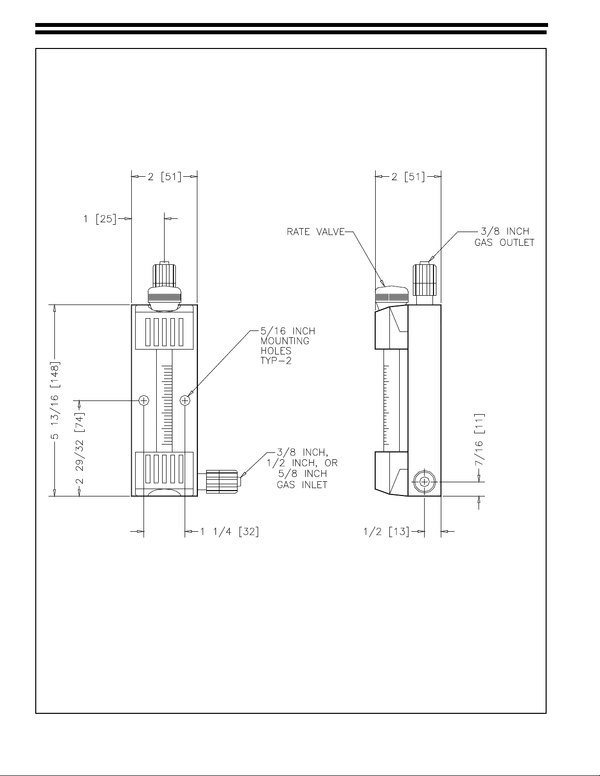
2.2 Installation - See Figures 1, 2, and 3
The remote meter panel must be installed in an upright and level position in order to function properly.
The remote meter panel is installed in the vacuum line between the ejector and the vacuum regulator. Locate
the meter panel on a vertical surface convenient for observation and operation, usually in the operator’s area,
with the point of chlorine injection at the desired remote location. Mount the meter panel using two (2) 1/4"
mounting screws for a 3" meter panel, or four (4) 3/8" mounting screws for a 6" meter panel. If the surface is
not suitable for wood screws, choose an appropriate anchor bolt to that surface.
Black polyethylene tubing is normally used for the vacuum line. Do not kink this tubing. It may be desirable
to use tubing connectors, tees or 90° elbows to provide as direct run as possible and minimize kinking
conditions. Use enough tubing length to allow movement of the vacuum regulator for servicing or cylinder
change. Connect the tubing as follows:
2.2.1 Remove the bottom vacuum inlet connector nut from the remote meter panel and slip the connector
nut onto the vacuum tubing coming from the vacuum regulator.
2.2.2 Push the tubing onto the tubing connector and tighten the connector nut HAND TIGHT.
2.2.3 Remove the connector nut from the vacuum outlet (top) of the remote meter and slip onto vacuum
tubing going to the ejector.
2.2.4 Push the tubing onto the tubing connector and tighten the connector nut HAND TIGHT.
NOTE: There may be installations where multiple meter panels may be used from one vacuum
regulator. If this occurs, additional tees may be required to complete the installation.
2.2.5 Some meter panels may be provided as a complete block with a common vacuum manifold, Each
meter would have an individual outlet.
General Design Note: Routing vacuum tubing through unventilated conduit is discouraged. A minute
portion of gas flowing through tubing under vacuum conditions, will slowly diffuse at a molecular
level through its walls and collect in the closed conduit over an extended period of time.
100.6015.10 - 6 -
Figure 1 - 100 PPD (2 kg/h) Meter Panel

- 7 - 100.6015.10
Figure 2 - 200 PPD (4 kg/h) Meter Panel

100.6015.10 - 8 -
Figure 3 - 500 PPD (10 kg/h) Meter Panel
250 PPD [5 kg/h] & 300PPD (6 kg/h) Chlorine only)
3 START-UP
Follow the instructions provided in the vacuum regulator instruction manual 100.6010 for complete system
start-up procedures.
After the system has been tested for leaks and is operating, adjust the rate valve to the desired gas flow rate.
The flow rates are in PPD (pounds per day) of chlorine.
If feeding sulfur dioxide, the actual flow rate is 0.95 of the scale value. For example, a reading of 50 PPD
(1 kg/h) is actually 45 PPD (0.95 kg/h) sulfur dioxide.
If feeding ammonia, the actual flow rate is 0.50 of the scale value. For example, a reading of 50 PPD (1 kg/h)
is actually 25 PPD (0.5 kg/h) ammonia.
Read the flowmeter scale at the center of the ball.
NOTE: NEVER use the rate valve on the remote meter panel to shut off the gas supply. This valve is for
adjusting flow rate while the system is in operation. If used for shutoff, this valve will be damaged. To shut off
the gas, close the gas container valve.

- 9 - 100.6015.10
Figure 4 - 100 PPD (2 kg/h) Meter Panel Components

100.6015.10 - 10 -
Figure 5 - 250 PPD Max (4 kg/h) Meter Panel Components
- 11 - 100.6015.10
Figure 6 - 300 (6 kg/h) & 500 PPD (10 kg/h) Meter Panel Components

100.6015.10 - 12 -
4 SERVICE
Preventative maintenance kits for each of the assemblies are available from the factory. Each kit contains all
the parts and detailed instructions that are required for complete maintenance. All o-rings and gaskets that
have been disturbed during the disassembly must be replaced during reassembly in order to insure safe,
trouble free operation. Failure to replace these parts could result in a shortened operation period and bodily
injury.
Refer to Figures 4, 5, and 6
4.1 Cleaning the Flowmeter Assembly
4.1.1 Use a coin or washer as a screwdriver and loosen the bottom meter inlet plug while holding the
flowmeter assembly to make sure it does not drop out. It may be necessary to use pliers if the plug
has not been removed for some time.
4.1.2 Loosen the plug about three (3) turns and remove the meter assembly. (Push up and out on the
flowmeter to remove).
4.1.3 Bend a paper clip or wire and pull out the ball stops on each end of the glass tube. DO NOT LOSE
THE METERING BALL.
4.1.4 Clean the inside of the glass tube with a pipe cleaner or bottle brush using wood alcohol, and rinse
thoroughly with warm water.
4.1.5 Clean the metering ball using wood alcohol, and rinse thoroughly with warm water.
4.1.6 Thoroughly dry the glass metering tube. Reassemble the metering stops and ball.
4.1.7 Reinstall the meter assembly by tightening the meter inlet plug making sure that it is on center with
the top and bottom gasket.
NOTE: The meter gaskets can usually be reused. Turn the gaskets over for best results.
4.2 Rate Valve Cleaning
4.2.1 Unscrew the rate valve plug from the valve bonnet.
4.2.2 Remove the valve bonnet from the top of the front body.
4.2.3 Clean the parts by immersing in alcohol or soapy water, rinse, and dry thoroughly with a clean cloth.
4.2.4 The o-rings on the valve bonnet may need replacing if scratched or bruised.
4.2.5 Examine the valve sleeve for nicks or any marks. The sleeve may be removed for this purpose. Use
caution to avoid marking the surfaces.
4.2.6 The o-ring on the outside of the valve sleeve usually may not require replacing.
4.2.7 Inspect the rate valve hole in the meter housing and clean with a damp cloth if necessary. DO NOT
use any sharp tools that may scratch the internal surface. Never use any solvent for cleaning the
plastic, as it will deteriorate rapidly. Wood alcohol can, however, be used successfully.
4.2.8 Apply a thin film of fluorolube grease to o-rings and slide the valve sleeve into the top body.
4.2.9 Replace rate valve.

- 13 - 100.6015.10
5 TROUBLESHOOTING CHART
Since the operating performance of the remote meter panel can be effected by the vacuum regulator and
ejector, also refer to the Troubleshooting Chart in bulletin 100.6005, 122.6006, 122.6010, or 122.6015.
TROUBLE PROBABLE CAUSE CORRECTIVE ACTION
1. The required gas feed rate is
not achieved at start-up.
a. Insufficient ejector vacuum due
to insufficient water supply pres
sure for existing back pressure
conditions.
b. Leakage at vacuum line
connections, vacuum regulator
and/or inlet to ejector.
c. Vacuum line(s) crimped.
d. Length of vacuum line(s)
exceeds maximum allowable
transport distance.
a. Refer to Trouble 2.
b. Inspect each connection and
remake as necessary.
c. Replace vacuum tubing and
arrange line(s) to eliminate
2. Flowmeter ball bounces and/or
maximum gas feed rate cannot
be achieved during normal
operation.
a. Vacuum regulator inlet filter
screen dirty.
b. Rate valve dirty.
c. Flowmeter dirty.
d. Ejector water supply pressure
fluctuating causing insufficient
ejector vacuum. (Ball bouncing
only)
a. Replace gas inlet filter.
b. Clean the rate valve. See
Service section.
c. Clean the flowmeter. See
Service section.
d. Check water supply pressure.
Correct as necessary
3. Flooded metering tube. a. Dirt on the ejector check valve
seat, or worn seat
a. Clean or replace ejector check
valve seat. Refer to Ejector
instruction manual 122.6006,
122.6010, or 122.6015.
4. Vacuum leaks a. Rate valve o-rings worn.
b. Tubing connector loose.
c. Cracks in tubing
a. Replace o-ring.
b. Tighten tubing connector.
c. Replace tubing.

100.6015.10 - 14 -
Represented by:
Design improvements may be made without notice.
SEP 2015
De Nora Water Technologies
3000 Advance Lane Colmar, PA 18915
ph +1 215 997 4000 • fax +1 215 997 4062
web: www.denora.com
mail: [email protected]
®Registered Trademark. © 2015. All Rights Reserved.
Table of contents
Other De Nora Measuring Instrument manuals

Popular Measuring Instrument manuals by other brands


Endress+Hauser
Endress+Hauser Proline Promag 55 operating manual

Emerson
Emerson Rosemount 585 Annubar Quick installation guide

TESTO
TESTO 230 instruction manual

Spectroline
Spectroline AccuPRO XP-2000 quick guide

Extech Instruments
Extech Instruments EN150 user manual

Seikom Electronic
Seikom Electronic RLSW 7 user manual