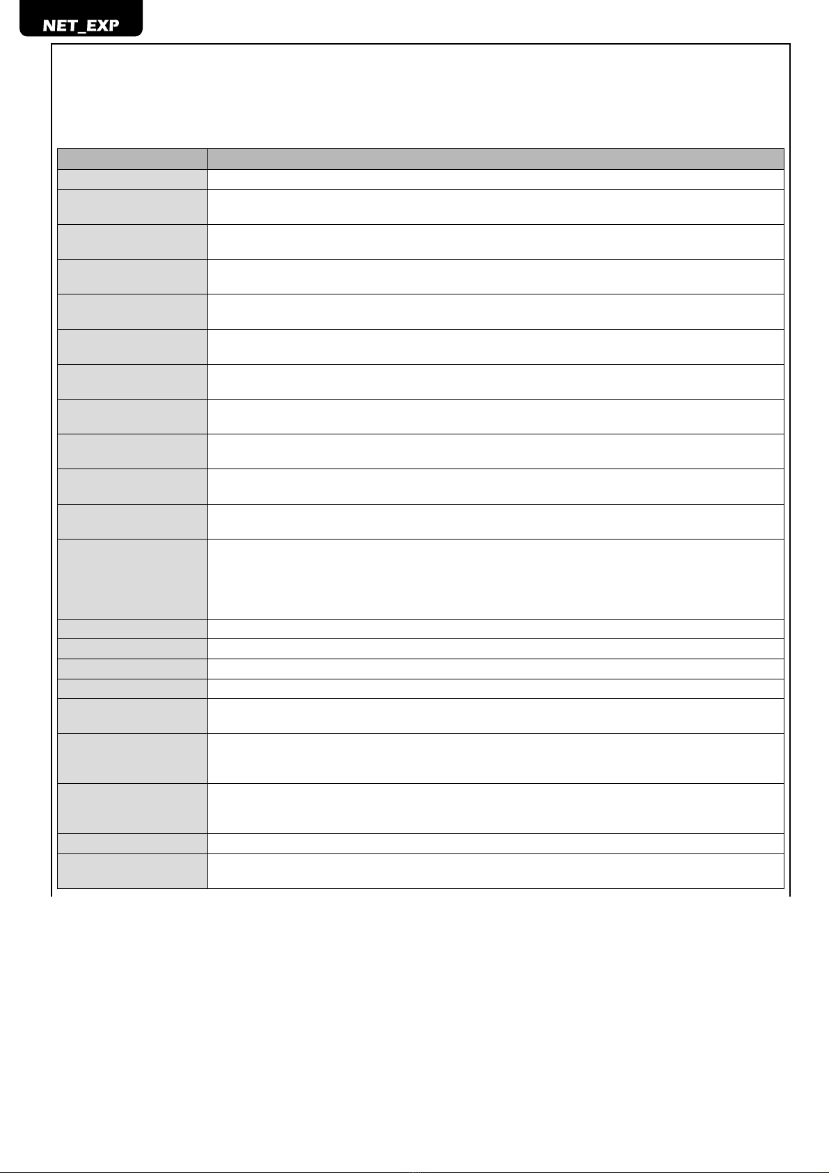
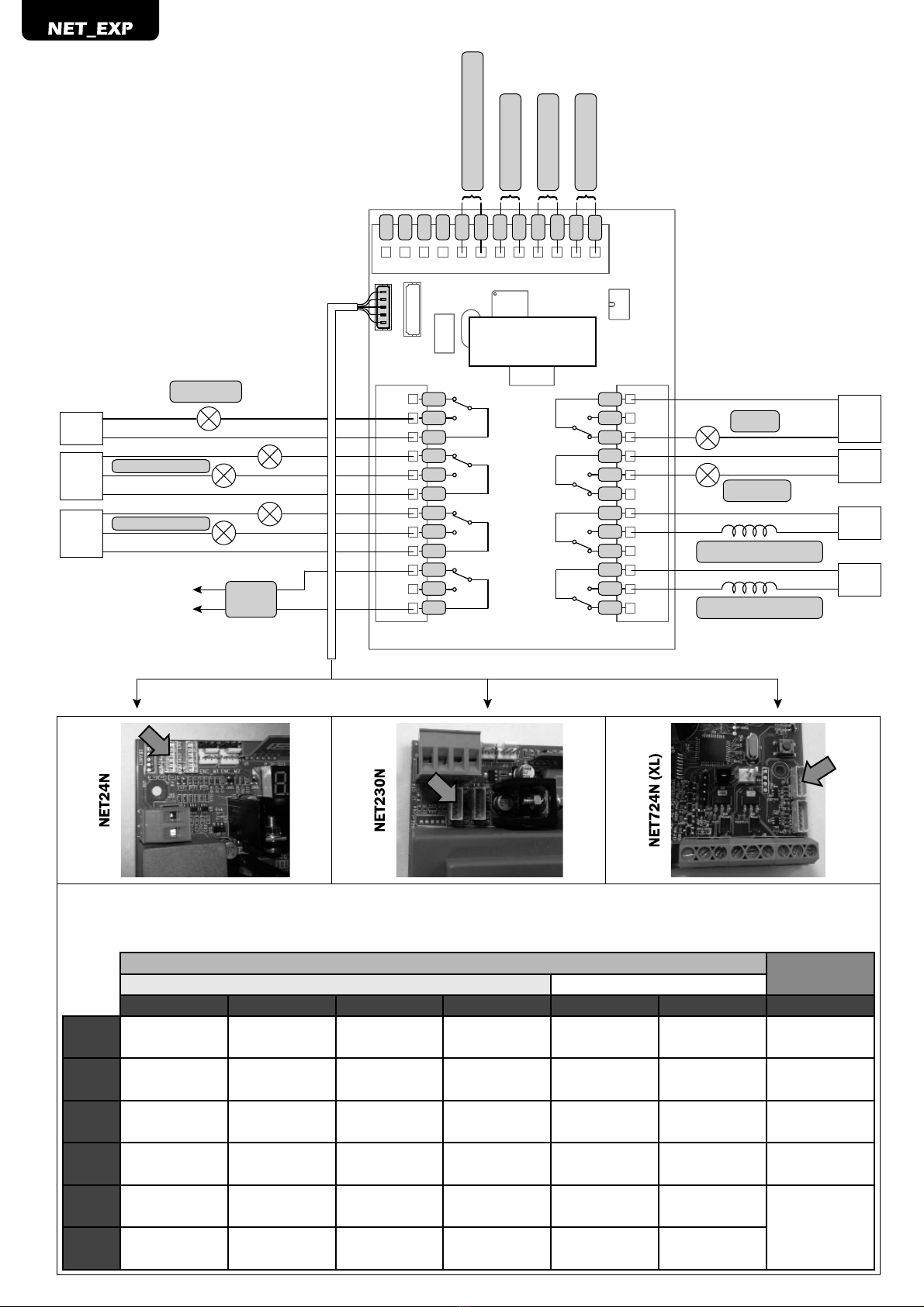
Dea NET EXP Product manual

NET_EXP
Scheda di espansione ingressi/uscite per centrali di comando serie NET
Istruzioni d’uso ed avvertenze
Input/output expansion board for NET series control units
Operating instructions and warnings
Carte d’expansion entrées/sorties pour unités de commande série NET
Notice d’emploi et avertissements
Erweiterungskarte Ein-/Ausgänge für Steuereinheiten der Baureihe NET
Bedienungsanleitung und Hinweise
Tarjeta de expansión entradas/salidas para centrales de control serie NET
Instrucciones de uso y advertencias
Placa de expansão entradas/saídas para centrais de comando série NET
Instruções para utilização e advertências
Karta rozszerzenia wejść/wyjść dla centralek sterowniczych serii NET
Instrukcja montażu i użytkowania
Плата расширения входов/выходов для подстанций управления серии NET
Инструкции ипредупреждения
I77009 Rev. 06 (28-09-2022)


IT-1
NET_EXP
Scheda di espansione ingressi/uscite per
centrali di comando serie NET
Istruzioni d’uso ed avvertenze
1 RIEPILOGO AVVERTENZE
ATTENZIONE L’utilizzo del prodotto in condizioni anomale non previste dal costruttore può generare
situazioni di pericolo; rispettare le condizioni previste dalle presenti istruzioni.
ATTENZIONE DEA System ricorda che la scelta, la disposizione e l’installazione di tutti i dispositivi ed
i materiali costituenti l’assieme completo della chiusura, devono avvenire in ottemperanza alle Direttive
Europee 2006/42/CE (Direttiva macchine), Direttiva 2014/53/UE (Direttiva RED). Per tutti i Paesi extra
Unione Europea, oltre alle norme nazionali vigenti, per un sufficiente livello di sicurezza si consiglia il
rispetto anche delle prescrizioni contenute nelle Direttive sopraccitate.
ATTENZIONE In nessun caso utilizzare il prodotto in presenza di atmosfera eplosiva o in ambienti che
possano essere aggressivi e danneggiare parti del prodotto.
ATTENZIONE Per una adeguata sicurezza elettrica in fase di installazione, utilizzare esclusivamente
cavi in doppio isolamento avendo cura di tenere nettamente separati (minimo 4 mm in aria o 1 mm
attraverso l’isolamento supplementare) il cavo di connessione NET_EXP e i cavi a bassissima tensione
di sicurezza (comandi, elettroserratura, antenna, alimentazione ausiliari) dai cavi di alimentazione 230V
~ provvedendo al loro fissaggio con adeguate fascette in prossimità delle morsettiere.
ATTENZIONE Qualsiasi operazione d’installazione, manutenzione, pulizia o riparazione dell’intero
impianto devono essere eseguite esclusivamente da personale qualificato; operare sempre in mancanza
dialimentazioneeseguirescrupolosamentetuttelenormevigentinelpaeseincuisieffettual’installazione,
in materia di impianti elettrici.
ATTENZIONE Eventuali dispositivi di sicurezza esterni utilizzati per il rispetto dei limiti delle forze
d’impatto devono essere conformi alla norma EN12978.
2 DESCRIZIONE DEL PRODOTTO
Le schede espansione “NET_EXP” e “NET_EXP mini”, sono accessori da abbinare esclusivamente alle centrali di comando serie NET.
ATTENZIONE è possibile innestare la scheda “NET_EXP mini” esclusivamente nelle centrali di comando NET24N e NET230N.
Tali dispositivi, permettono di gestire fino a 8 uscite (per ciascuna di esse è presente sia l’uscita N.C. che N.O.) e 6 ingressi aggiuntivi.
Inoltre come per le centrali serie NET, per ciascun ingresso/uscita in uso è possibile scegliere un funzionamento personalizzato garantendo
quindi la massima adattabilità ad ogni tipo di impianto da automatizzare.
3 DATI TECNICI
Per tutte le uscite: Per tutti gli ingressi:
Configurazione contatti Configurabili a scelta tra:
- Contatto pulito;
- Resistenza costante 8K2.
Tensione nominale NET_EXP 250 V ~ / 30 V
NET_EXP mini 12-24 V dc/ac
Corrente nominale Max 2 A (solo carichi resistivi)

IT-2
4 DESCRIZIONE LED DI STATO
NET_EXP
LD1 Led verde fisso: La scheda espansione è alimentata.
Led spento: La scheda espansione non è alimentata.
LD2 Non utilizzato
LD3
Led rosso lampeggiante: La scheda espansione è abilitata.
Led spento: La scheda espansione non è abilitata oppure il cavo di collegamento non è cablato correttamente
alla centrale di comando.
LD4 Led verde lampeggiante: Indica il corretto funzionamento del software interno.
Led spento: Indica un malfunzionamento della scheda espansione.
NET_EXP mini
Led fisso: La scheda espansione è alimentata e comunica correttamente.
Led spento: La scheda espansione non è alimentata.
Led lampeggiante: La scheda espansione è alimentata ma non comunica correttamente.
5 ABILITAZIONE SCHEDA NET_EXP
ATTENZIONE Il collegamento della scheda espansione NET_EXP va eseguito con la scheda di comando NET spenta.
Seguire quanto descritto di seguito per il corretto cablaggio e l’abilitazione della scheda espansione:
NET_EXP
1. Con alimentazione spenta, collegare la scheda espansione alla centrale di comando NET servendosi dell’apposito cavetto in
dotazione. Assicurarsi che il cavetto sia cablato correttamente.
2. Dare alimentazione alla centrale (il LED verde LD1 si accende fisso mentre il LED verde LD4 si accente lampeggiante).
3. Abilitare l’espansione impostando il parametro P078=1. Il LED rosso LD3 lampeggiante conferma la corretta comunicazione della
scheda con la centrale di comando. Se spento segnala l’assenza di comunicazione (controllare la corretta impostazione del parametro e
che il cavetto di connessione non sia danneggiato o disinserito).
NET_EXP mini
1. Con alimentazione spenta, innestare la scheda espansione alla centrale di comando NET24N o NET230N come indicato e
collegare l’apposito cavetto in dotazione. Assicurarsi che il cavetto sia cablato correttamente.
CIN1CIN2CIN3CIN4CIN5CIN6
NET24N - NET230N
2. Dare alimentazione alla centrale (il LED si accende lampeggiante).
3. Abilitare l’espansione impostando il parametro P078=1. Il LED acceso con luce fissa, conferma la corretta comunicazione della
scheda con la centrale di comando. Se lampeggiante, indica un problema di comunicazione (controllare la corretta impostazione del
parametro e che il cavetto di connessione non sia danneggiato o disinserito).
ATTENZIONE Abilitando l’espansione anche i relativi ingressi e uscite sono già configurati per un’installazione standard. Ricordarsi
di ponticellare gli eventuali ingressi NC non utilizzati dell’espansione, prima di qualsiasi altra operazione.
ATTENZIONE Ad ogni ripristino delle impostazioni I/O (P010), i parametri sopra indicati vengono modificati per default (disattivando la
scheda espansione). Ricordarsi di impostarli nuovamente come indicato prima di qualsiasi altra operazione.

IT-3
6 CONFIGURAZIONE INGRESSI E USCITE
Nel caso in cui l’installazione richieda comandi diversi e/o aggiuntivi rispetto
allo standard descritto dagli schemi elettrici, è possibile configurare ciascun
ingresso/uscita per il funzionamento desiderato.
1. Scorrere i parametri con i tasti e fino a visualizzare quello
desiderato:
INPUT OUTPUT
●P085=per INPUT 1; ●P091=per OUTPUT 1;
●P086=per INPUT 2; ●P092=per OUTPUT 2;
●P087=per INPUT 3; ●P093=per OUTPUT 3;
●P088=per INPUT 4; ●P094=per OUTPUT 4;
●P089=per INPUT 5; ●P095=per OUTPUT 5;
●P090=per INPUT 6; ●P096=per OUTPUT 6;
●P097=per OUTPUT 7;
●P098=per OUTPUT 8;
2. Accedere al parametro (es. P093) premendo il tasto ;
3. Agendo sui tasti e , impostare il valore corrispondente al
funzionamento desiderato (fare riferimento alla tabella ”parametri di
configurazione” a pag. IT-8);
4. Confermare la scelta premendo il tasto (sul display ricompare P093).
5. Eseguire il collegamento appena configurato.
ATTENZIONE Alla fine della procedura di configurazione, agire sui tasti e fino alla comparsa del simbolo “----“,l’automatismo è
ora in attesa di comandi per il funzionamento normale.
NET_EXP NET_EXP mini
C
C
IN5
IN4
C
C
IN6
IN3
C
IN2
IN1
C
C
NC
C
NC
C
NC
NO
NO
NO
C
NC
NO
NC
C
NC
C
NC
C
NO
NO
NO
NC
C
NO
OUT5OUT6OUT7OUT8
OUT1OUT2OUT3OUT4
--> TO NET BOARD -->
LED 4
LED 3
LED 2
LED 1
--> TO NET BOARD -->
NC
NO
C
IN1
IN1
IN2
IN3
IN4
IN5
IN6
C
C
CC
C
IN4
IN2
IN3
NET BOARD
OUT1
NET-EXP MINI
LED

IT-4
7 DESCRIZIONE INGRESSI E USCITE
Le tabelle sottoriportate, offrono una descrizione del funzionamento di tutte le possibili selezioni sia per gli ingressi che per le uscite
presenti nella scheda NET_EXP. Fare riferimento anche alla tabella di configurazione parametri.
INGRESSI
SELEZIONE DESCRIZIONE
NONE Non utilizzato.
START "Ingresso N.O. start. In caso di intervento provoca l’apertura o la chiusura. Può funzionare
in modalità “inversione” (P049=0) o “passo - passo” (P049=1)."
PED. "Ingresso N.O. pedonale. In caso di intervento provoca l’apertura parziale del
cancello. La regolazione della durata della corsa pedonale è impostabile con il P043."
OPEN "Ingresso N.O. apre. In caso di intervento provoca l’apertura del cancello."
CLOSE Ingresso N.O. chiude. In caso di intervento provoca la chiusura del cancello.
OPEN_PM Ingresso N.O. apertura uomo presente. Per il tempo in cui si tiene premuto il pulsante il cancello esegue
l'apertura.
CLOSE_PM Ingresso N.O. chiusura uomo presente. Per il tempo in cui si tiene premuto il pulsante il cancello esegue la
chiusura.
ELOCK_IN Ingresso N.O. attivazione uscita elettroserratura. In caso di intervento provoca l'attivazione dell'uscita "LOCK"
della scheda, vedere P062.
PHOTO 1 Ingresso N.C. fotocellula 1. Per la selezione della modalità di funzionamento vedere P050. Se non utilizzato
ponticellare l'ingresso.
PHOTO 2 Ingresso N.C. fotocellula 2. Per la selezione della modalità di funzionamento vedere P051. Se non utilizzato
ponticellare l'ingresso.
SAFETY 1 Ingresso N.C. costa sensibile 1. Per la selezione della modalità di funzionamento vedere P067. Se non
utilizzato ponticellare l'ingresso.
STOP (SAS INPUT)
Contatto N.C. (SAS INPUT): Se collegato a WARN_FIX/SAS OUTPUT in una seconda centrale, provoca il fun-
zionamento “porta bancaria” (disabilitazione dell’apertura della seconda porta fintanto che la prima non è
completamente chiusa).
Ingresso N.C. stop. In caso di intervento blocca il movimento durante qualsiasi manovra. Se non utilizzato
ponticellare l'ingresso.
FCA1 Ingresso N.C. finecorsa apertura motore 1. Se non utilizzato disabilitare l'ingresso con il relativo parametro.
FCA2 Ingresso N.C. finecorsa apertura motore 2. Se non utilizzato disabilitare l'ingresso con il relativo parametro.
FCC1 Ingresso N.C. finecorsa chiusura motore 1. Se non utilizzato disabilitare l'ingresso con il relativo parametro.
FCC2 Ingresso N.C. finecorsa chiusura motore 2. Se non utilizzato disabilitare l'ingresso con il relativo parametro.
SAFETY 2 Ingresso N.C. costa sensibile 2. Per la selezione della modalità di funzionamento vedere P068. Se non
utilizzato ponticellare l'ingresso.
OPEN_INT
Avvia la manovra e abilita l’accensione della lampada verde (all’arrivo in cancello aperto) per il solo semaforo
interno. Se nel frattempo viene dato un comando OPEN_EXT, questo si prenota per la prossima manovra, e
al temine del TCA si accende la lampada verde del semaforo esterno.
OPEN_EXT
Avvia la manovra e abilita l’accensione della lampada verde (all’arrivo in cancello aperto) per il solo semaforo
esterno. Se nel frattempo viene dato un comando OPEN_INT, questo si prenota per la prossima manovra, e
al temine del TCA si accende la lampada verde del semaforo interno.
AUX_IN Ingresso per il comando dell’uscita AUX_OUT.
SAFETY INHIBITION Ingresso N.C. Inibizione SAFETY. Quando aperto, provoca il bypass degli ingressi SAFETY che vengono
ignorati anche se attivi.

IT-5
USCITE
SELEZIONE DESCRIZIONE
NONE Non utilizzato
WARN_FIX (SAS OUT)
Contatto N.C. (SAS OUTPUT): Se collegato a STOP/SAS INPUT in una seconda centrale, provoca il funzio-
namento “porta bancaria” (disabilitazione dell’apertura della seconda porta fintanto che la prima non è
completamente chiusa).
Contatto N.O. (WARN_FIX): Funzionamento come spia cancello aperto fissa.
WARN_INT Spia cancello aperto intermittente: uscita intermittente lento durante apertura e veloce durante chiusura,
sempre ON con cancello aperto, sempre OFF solo al termine di una manovra di chiusura.
FLASH_FIX Contatto N.O. Uscita lampeggiante fissa.
FLASH_INT Contatto N.O. Uscita lampeggiante intermittente.
ELOCK M1 Contatto N.O. Uscita per elettroserratura motore 1.
ELOCK M2 Contatto N.O. Uscita per elettroserratura motore 2.
ELOCK_INV M1 Contatto N.O. Uscita per elettroserratura invertita motore 1 (ad esempio per il funzionamento dell'elettroma-
gnete delle barriere).
ELOCK_INV M2 Contatto N.O. Uscita per elettroserratura invertita motore 2 (ad esempio per il funzionamento dell'elettroma-
gnete delle barriere).
ELETTRO_BRAKE M1 Contatto N.O. Uscita per freno motore 1 (reversibile).
ELETTRO_BRAKE M2 Contatto N.O. Uscita per freno motore 2 (reversibile).
MINUTERIE Contatto N.O. Il contatto si chiude per 3 sec. all’inizio di ogni manovra.
ALARM
Contatto N.C. Il contatto rimane sempre aperto e si chiude quando l’avvio di una manovra fallisce a causa di
un ingresso di sicurezza (Photo, Safety, Stop) attivo. Il contatto ritorna aperto quando un successivo tentativo
di avvio di una manovra va a buon fine. In caso di mancanza di alimentazione, il contatto è chiuso e quindi
può essere usato per generare un allarme.
TRAFFIC_LIGHT_INT
In uscita dal relè, il contatto N.C. alimenta la lampada rossa, il contatto N.O. quella verde. Con cancello
chiuso e/o motori in movimento, il semaforo è rosso (nel caso si utilizzi lo schema di collegamento di pag. 8,
con porta chiusa i semafori sono spenti). Solo con cancello aperto il relè scambia e si accende il semaforo
verde. Nel caso di funzionamento con 2 semafori, uno interno ed uno esterno, e l’attivazione avvenga da
comandi START/OPEN/CLOSE i due semafori funzionano allo stesso modo. Nel caso di funzionamento con
priorità (attivazione da comandi OPEN_INT/OPEN_EXT), solo il semaforo corrispondente all’ingresso diventa
verde quando il cancello è aperto, l’altro rimane rosso. Inoltre dopo un reset i semafori sono rossi e al primo
comando la centrale eseguirà una ricerca delle battute/finecorsa durante il quale i semafori resteranno rossi
fino al termine della manovra. Se si volesse avere un tempo di sgombero bisognerà selezionare un tempo di
chiusura automatica (TCA) con il P041, tenendo presente che questo tempo impostato dovrà essere almeno
il doppio di quello previsto per la percorrenza del tratto tra i 2 semafori. Per cui in apertura i semafori rimar-
ranno verdi per un tempo TCA/2, mentre per la seconda metà del TCA i semafori resteranno rossi per dare il
tempo ad eventuali veicoli di sgomberare il passaggio.
Al fine di evitare il formarsi di code, per il tempo in cui il semaforo è verde accetta sempre il comando priorita-
rio che lo aveva attivato ricominciando da 0 il TCA. Un eventuale prenotazione ha effetto appena il semaforo
diventa rosso e al termine del TCA diverrà verde il semaforo relativo all’altro senso di marcia.
TRAFFIC_LIGHT_EXT
AUX_OUT_ INPULS Contatto N.O. Uscita comandata da ingresso AUX_IN in modalità impulsiva.
AUX_OUT_STEP Contatto N.O. Uscita comandata da ingresso AUX_IN in modalità passo-passo.
AUX_OUT_TEMP Contatto N.O. Uscita comandata da ingresso AUX_IN in modalità temporizzata (il valore impostato con il
P099 indica il ritardo di spegnimento in secondi).

IT-6
COM 1
N.O. 1
N.C. 1
COM 2
N.O. 2
N.C. 2
COM 3
N.O. 3
N.C. 3
COM 4
N.O. 4
N.C. 4
N.C. 8
N.O. 8
COM 8
N.C. 7
N.O. 7
COM 7
N.C. 6
N.O. 6
COM 6
N.C. 5
N.O. 5
COM 5
ALARM
OPEN_int (N.O.)
OPEN_ext (N.O.)
SAFETY 2 (N.C.)
STOP (SAS Input) (N.C.)
GREEN
RED
GREEN
RED
TRAFFIC_LIGHT_EXT
TRAFFIC_LIGHT_INT
ELETTRO_BRAKE M2
ELETTRO_BRAKE M1
WARN_FIX
MINUTERIE
SAS
Output
COM 6
N.C. 6
COM 5
N.C. 5
COM 3
N.C. 3
COM 2
N.O. 2
COM 4
N.C. 4
COM 1
N.O. 1
NET_EXP
+V / ~
-V / ~
+V / ~
-V / ~
+V / ~
-V / ~
+V / ~
-V / ~
+V / ~
-V / ~
+V / ~
-V / ~
+V / ~
-V / ~
Tabella di riferimento per gli INPUT a seconda del modello in uso - Reference table for INPUT according to the model in use - Tableau de référence pour
INPUT selon le modèle utilisé - Referenztabelle für INPUT gemäß dem verwendeten Modell - Tabla de referencia para INPUT según el modelo en uso - Tabela
de referência para INPUT de acordo com o modelo em uso - Tabela referencyjna dla INPUT według używanego modelu - Справочная таблица для INPUT в
соответствии сиспользуемой моделью
NET230N NET724N
NET724NXL
NET24N /
TYPE 00 TYPE 01 TYPE 02 TYPE 03 TYPE 04 TYPE 05 TYPE 04
INPUT 1 001 001 001 001 001 003 008
START (N.O.) START (N.O.) START (N.O.) START (N.O.) START (N.O.) OPEN (N.O.) PHOTO 1 (N.C.)
INPUT 2 002 002 008 008 008 004 001
PED. (N.O.) PED. (N.O.) PHOTO 1 (N.C.) PHOTO 1 (N.C.) PHOTO 1 (N.C.) CLOSE (N.O.) START (N.O.)
INPUT 3 010 010 010 000 000 010 000
SAFETY (N.C.) SAFETY (N.C.) SAFETY (N.C.) NONE (N.O.) NONE (N.O.) SAFETY (N.C.) NONE (N.O.)
INPUT 4 008 008 011 000 011 008 000
PHOTO 1 (N.C.) PHOTO 1 (N.C.) STOP (N.C.) NONE (N.O.) STOP (N.C.) PHOTO 1 (N.C.) NONE (N.O.)
INPUT 5 012 009 000 000 012 012
/
FCA 1 (N.C.) PHOTO 2 (N.C.) NONE (N.O.) NONE (N.O.) FCA 1 (N.C.) FCA 1 (N.C.)
INPUT 6 014 011 000 000 014 014
FCC 1 (N.C.) STOP (N.C.) NONE (N.O.) NONE (N.O.) FCC 1 (N.C.) FCC 1 (N.C.)

IT-7
Schema di collegamento per semaforo spento con cancello chiuso
COM 1
N.O. 1
N.C. 1
COM 2
N.O. 2
N.C. 2
COM 3
N.O. 3
N.C. 3
COM 4
N.O. 4
N.C. 4
N.C. 8
N.O. 8
COM 8
N.C. 7
N.O. 7
COM 7
N.C. 6
N.O. 6
COM 6
N.C. 5
N.O. 5
COM 5
Verde
Rossa
Verde
Rossa
TRAFFIC_LIGHT_EXT
TRAFFIC_LIGHT_INT
SAS
Output
COM 6
N.C. 6
COM 5
N.C. 5
COM 3
N.C. 3
COM 2
N.O. 2
COM 4
N.C. 4
COM 1
N.O. 1
NET_EXP
+V / ~
-V / ~
ATTENZIONE
Se si utilizza la configurazione del presente schema di collegamento, ricordarsi di impostare il parametro:
P053=0 / P072=1 (solo NET24 - NET230)
P072=0 (solo NET724)
8 MESSAGGI VISUALIZZATI SUL DISPLAY
MESSAGGI DI ERRORE
Mess. Descrizione Possibili soluzioni
Comunicazione con scheda espansione interrotta. Verificare che il cavo di connessione tra la scheda espansione NET_EXP e la centrale
di comando sia correttamente agganciato e nella posizione corretta.
9 DISMISSIONE DEL PRODOTTO
ATTENZIONE In ottemperanza alla Direttiva UE 2012/19/CE sui rifiuti di apparecchiature elettriche ed elettroniche (WEEE), questo
prodotto elettrico non deve essere smaltito come rifiuto municipale misto. Si prega di smaltire il prodotto portandolo al punto di
raccolta municipale locale per un opportuno riciclaggio.

IT-8
PAR. DESCRIZIONE PARAMETRO
PARAMETRI DI CONFIGURAZIONE
Abilitazione scheda espansione NET_EXP:
Attenzione: Da default la scheda espansione è disabilitata.
Attenzione: Se si effettua un default delle impostazioni, ricordarsi di impostare correttamente i parametri.
Selezione tipo ingresso INPUT_1
Selezione tipo ingresso INPUT_2
Selezione tipo ingresso INPUT_3
Selezione tipo ingresso INPUT_4
Selezione tipo ingresso INPUT_5
Selezione tipo ingresso INPUT_6
Selezione funzionamento INPUT_1
Selezione funzionamento INPUT_2
Selezione funzionamento INPUT_3
Selezione funzionamento INPUT_4
Selezione funzionamento INPUT_5
Selezione funzionamento INPUT_6

IT-9
VALORI SELEZIONABILI
VALORI DI DEFAULT
(per i diversi standard di installazione)
NET24N - NET230N NET724N - NET724NXL
• 000: Disabilitato
• 001: Abilitato
• 000: contatto pulito
• 001: resist. costante 8K2
• 000: NONE
• 001: START
• 002: PED.
• 003: OPEN
• 004: CLOSE
• 005: OPEN_PM
• 006: CLOSE_PM
• 007: ELOCK_IN
• 008: PHOTO 1
• 009: PHOTO 2
• 010: SAFETY 1
• 011: STOP (SAS INPUT)
• 012: FCA1
• 013: FCA2
• 014: FCC1
• 015: FCC2
• 016: SAFETY 2
• 017: OPEN_INT
• 018: OPEN_EXT
• 019: AUX_IN
• 020: SAFETY INHIBITION
IN1
IN2
IN3
IN4
IN5
IN6

IT-10
PAR. DESCRIZIONE PARAMETRO
PARAMETRI DI CONFIGURAZIONE
Selezione funzionamento OUTPUT_1
Selezione funzionamento OUTPUT_2
Selezione funzionamento OUTPUT_3
Selezione funzionamento OUTPUT_4
Selezione funzionamento OUTPUT_5
Selezione funzionamento OUTPUT_6
Selezione funzionamento OUTPUT_7
Selezione funzionamento OUTPUT_8
Funzionamento uscita AUX_OUT_TEMP (se attiva):
Se=0 disabilitato;
Se>0 uscita comandata da ingresso AUX_IN in modalità temporizzata (il valore impostato indica il ritardo di
spegnimento in secondi).

IT-11
VALORI SELEZIONABILI
VALORI DI DEFAULT
(per i diversi standard di installazione)
NET24N - NET230N NET724N - NET724NXL
• 000: NONE
• 001: WARN_FIX (SAS OUTPUT)
• 002: WARN_INT
• 003: FLASH_FIX
• 004: FLASH_INT
• 005: ELOCK M1
• 006: ELOCK M2
• 007: ELOCK_INV M1
• 008: ELOCK_INV M2
• 009: ELETTRO_BRAKE M1
• 010: ELETTRO_BRAKE M2
• 011: MINUTERIE
• 012: ALARM
• 013: TRAFFIC_LIGHT_INT
• 014: TRAFFIC_LIGHT_EXT
• 015: AUX_OUT_INPULS
• 016: AUX_OUT_STEP
• 017: AUX_OUT_TEMP
OUT1
OUT2
OUT3
OUT4
OUT5
OUT6
OUT7
OUT8
• 000: “Disabilitato
• >000: “Uscita temporizzata
(1sec………………255sec)

IT-12

EN-1
NET_EXP
Input/output expansion board for NET
series control units
User instructions and warnings
1 WARNINGS SUMMARY
WARNING The use of the product in abnormal conditions not foreseen by the manufacturer may lead
to hazardous situations; abide by the conditions prescribed in these instructions.
WARNING DEA System points out that the selection, layout and installation of all equipment and
materials of the complete automation system must be done in accordance with European Directives
2006/42/EC (Machinery Directive), Directive 2014/53/UE (RED Directive). For all countries outside the
European Union, in addition to the national rules in force we recommend compliance with the above-
mentioned Directives for a sufficient level of safety.
WARNING Never use the product in the presence of explosive atmospheres or environments that may
be aggressive to and damage product parts.
WARNING To ensure appropriate electrical safety during installation only use double insulation cables
and make sure to keep the NET_EXP connection cable and extra-low safety voltage cables (controls,
electric lock, antenna, auxiliary power) distinctly separate from the 230 ~ power cables (at least 4 mm
in the air or otherwise 1 mm by using additional insulation) by fixing them with suitable clamps near
the terminal board.
WARNING Any installation, maintenance, cleaning or repair operations of the entire system must be
only carried out by qualified personnel; always work without power supply and strictly comply with all
electrical system standards in force in the country in which the system is installed.
WARNING Any external safety devices used to comply with the impact force limits must comply with
the EN12978 standard.
2 PRODUCT DESCRIPTION
The “NET_EXP” and “NET_EXP mini” expansion boards are accessories that are only supported by NET series control units.
CAUTION, the “NET_EXP mini” board is only supported by NET24N and NET230N control units.
These devices let you control up to 8 outputs (an N.C. and N.O. output is included for each) and 6 additional inputs. Furthermore, like
NET series units, a custom function can be selected for each input/output used, thus guaranteeing maximum adaptability to any type of
plant to be automated.
3 TECHNICAL DATA
For all outputs: For all inputs:
Contacts configuration Configurations to choose from:
- Free contact;
- 8K2 constant resistance.
Rated voltage NET_EXP 250 V ~ / 30 V
NET_EXP mini 12-24 V dc/ac
Rated current Max 2 A (only resistive loads)

EN-2
4 STATUS LEDS DESCRIPTION
NET_EXP
LD1 Steady green LED: The expansion board is powered.
LED off: The expansion board is not powered.
LD2 Not used.
LD3 Flashing red LED: The expansion board is enabled.
LED off: The expansion board is not enabled or the connection cable is not correctly wired to the control unit.
LD4 Flashing green LED: Indicates the correct functioning of the internal software.
LED off: Indicates a malfunctioning of the expansion board.
NET_EXP mini
Led on: The expansion board power is on and it communicates correctly.
Led off: The expansion board power is off.
Led flashing: The expansion board power is on but it does not communicate correctly.
5 ENABLING THE NET_EXP BOARD
WARNING The NET_EXP expansion’s connection must be made with the NET control panel off.
Follow the instructions below for proper wiring and enabling the expansion board:
NET_EXP
1. With the power off, connect the expansion board to the NET control unit using the appropriate cable provided. Make sure the cable
is correctly wired.
2. Power the control unit (green LD1 LED shows a steady light while green LD4 LED flashes).
3. Enable the expansion by setting the P078 parameter to 1. The flashing red LD3 LED confirms correct interfacing of the board with
the control unit. If this is not on, it means that there is no interfacing (check correct setting of parameters and that the connection cable is
not damaged or disconnected).
NET_EXP mini
1. With the power off, insert the expansion board in the NET24N or NET230N control unit as indicated and connect the supplied
cable. Make sure the cable is correctly wired.
CIN1CIN2CIN3CIN4CIN5CIN6
NET24N - NET230N
2. Turn on unit power (the LED turns on flashing).
3. Enable the expansion board by setting parameter P078=1. The LED remains on to confirm correct board communications with the
control unit. If flashing, it indicates a communication problem (check correct parameter settings and make sure the connection cable is not
damaged or detached).
WARNING By enabling the expansion the relative inputs and outputs are already configured for standard installation. Remember to
jumper connect any unused NC inputs of the expansion, before any other operation.
WARNING Each time the I/O (P010) settings are reset, the parameters indicated above are changed to default settings (this deactivates
the expansion board). Before any other operation, remember to set the parameters again as explained.

EN-3
6 INPUTS AND OUTPUTS CONFIGURATION
Each input/output may be configured for the desired function if the installation
requires different and/or additional controls compared to the standard
described in the wiring diagrams.
1. Scroll the parameters with the and buttons until the parameter
desired is displayed:
INPUT OUTPUT
●P085=for INPUT 1; ●P091=for OUTPUT 1;
●P086=for INPUT 2; ●P092=for OUTPUT 2;
●P087=for INPUT 3; ●P093=for OUTPUT 3;
●P088=for INPUT 4; ●P094=for OUTPUT 4;
●P089=for INPUT 5; ●P095=for OUTPUT 5;
●P090=for INPUT 6; ●P096=for OUTPUT 6;
●P097=for OUTPUT 7;
●P098=for OUTPUT 8;
2. Access the parameters (i.e. P093) by pressing the button;
3. By using the and , buttons, set the value corresponding to the desi-
red functions (refer to the “configuration parameters” table on page EN-
8);
4. Confirm the selection by pressing the button (P093 appears on the
display screen).
5. Carry out the connection you have just configured.
WARNING At the end of the configuration procedure, use the and buttons until the “- - - -“ symbol appears; the automatism is now
pending commands for normal functioning.
NET_EXP NET_EXP mini
C
C
IN5
IN4
C
C
IN6
IN3
C
IN2
IN1
C
C
NC
C
NC
C
NC
NO
NO
NO
C
NC
NO
NC
C
NC
C
NC
C
NO
NO
NO
NC
C
NO
OUT5OUT6OUT7OUT8
OUT1OUT2OUT3OUT4
--> TO NET BOARD -->
LED 4
LED 3
LED 2
LED 1
--> TO NET BOARD -->
NC
NO
C
IN1
IN1
IN2
IN3
IN4
IN5
IN6
C
C
CC
C
IN4
IN2
IN3
NET BOARD
OUT1
NET-EXP MINI
LED

EN-4
7 INPUTS AND OUTPUTS DESCRIPTION
The tables below provide a description of the functioning of all possible selections for both the inputs and the outputs on the NET_EXP
board. Also refer to the table configuration parameters.
INPUTS
SELECTION DESCRIPTION
NONE Not used.
START N.O. input start. In case of action, this results in the opening or closing. It may function in “inversion”
(P049=0) or “step-by-step” (P049=1) modality.
PED. N.O. pedestrian start. In case of action, this results in the partial opening of the gate. The adjustment of the
pedestrian pace can be set with P043.
OPEN N.O. input open. In case of action, this results in the partial opening of the gate.
CLOSE N.O. input close. In case of action, this results in the closing of the gate.
OPEN_PM Dead man N.O. input open The gate opens for the amount of time in which the button is pressed.
CLOSE_PM Dead man N.O. input close The gate closes for the amount of time in which the button is pressed.
ELOCK_IN Electric lock activation N.O. input. In case of action, this leads to the activation of the “LOCK” output of the
board, see P062.
PHOTO 1 Photoelectric cell 1 N.C. input. See P050 to select the operation mode. If this is not used, bridge out the
connection.
PHOTO 2 Photoelectric cell 2 N.C. input. See P051 to select the operation mode. If this is not used, bridge out the
connection.
SAFETY 1 Sensitive edge 1 N.C. input. See P067 to select the operation mode. If this is not used, bridge out the
connection.
STOP (SAS INPUT)
N.C. contact. (SAS INPUT): If connected to WARN_FIX/SAS OUTPUT of a second control unit, causes the “bank
door” to operate (disabling the opening of the second door until the first is not fully closed).
Stop N.C. input. In case of action, this stops the movement during any manoeuvre. If this is not used, bridge
out the connection.
FCA1 Motor 1 opening end stop N.C. input If not used, disable the input with the corresponding parameter.
FCA2 Motor 2 opening end stop N.C. input If not used, disable the input with the corresponding parameter.
FCC1 Motor 1 closing end stop N.C. input If not used, disable the input with the corresponding parameter.
FCC2 Motor 2 closing end stop N.C. input If not used, disable the input with the corresponding parameter.
SAFETY 2 Sensitive edge 2 N.C. input. See P068 to select the operation mode. If this is not used, bridge out the
connection.
OPEN_INT
Starts the operation and enables the green light ignition (arrival at open gate) only for the internal traffic
light. Meanwhile, if the OPEN_EXT command is given, this books the next operation and the green light of the
external traffic light turns on at the end of the Automatic Closing Time (ACT).
OPEN_EXT
Starts the operation and enables the green light ignition (arrival at open gate) only for the external traffic
light. Meanwhile, if the OPEN_INT command is given, this books the next operation and the green light of the
internal traffic light turns on at the end of the Automatic Closing Time (ACT).
AUX_IN Input for the control of the AUX_OUT output.
SAFETY INHIBITION N.C. input SAFETY inhibition. When open, it causes the by-pass of the SAFETY inputs, which are ignored even
if activated.

EN-5
OUTPUTS
SELECTION DESCRIPTION
NONE Not used.
WARN_FIX (SAS OUT)
N.C. contact. (SAS OUTPUT): If connected to STOP/SAS INPUT of a second control unit, causes the “bank
door” to operate (disabling the opening of the second door until the first is not fully closed).
N.O. contact. (WARN_FIX): Operation as a fixed gate open indicator.
WARN_INT Flashing gate open light: Flashing output during slow opening and fast closing, always ON when the gate is
open, always OFF only at the end of a closing.
FLASH_FIX N.O. contact. Fixed flashing output.
FLASH_INT N.O. contact. Intermittent flashing output.
ELOCK M1 N.O. contact. Output for motor 1 electric lock.
ELOCK M2 N.O. contact. Output for motor 2 electric lock.
ELOCK_INV M1 N.O. contact. Output for motor 1 inverted electric lock (i.e. for the operating of the barrier electro magnet).
ELOCK_INV M2 N.O. contact. Output for motor 2 inverted electric lock (i.e. for the operating of the barrier electro magnet).
ELETTRO_BRAKE M1 N.O. contact. Output for motor 1 brake (reversible).
ELETTRO_BRAKE M2 N.O. contact. Output for motor 2 brake (reversible).
MINUTERIE N.O. contact. The contact closes for 3 seconds at the start of each manoeuvre.
ALARM
N.C. contact. The contact is always open and closes when the start of a manoeuvre fails because of an ac-
tivated safety input (Photo, Safety, Stop). The contact returns to open when a subsequent attempt to start
a manoeuvre is successful. In case of a power failure, the contact is closed and, therefore, can be used to
generate an alarm.
TRAFFIC_LIGHT_INT
Output from the relay, the N.C contact supplies the red light and the N.O. contact supplies the green light.
The light is red when the gate is closed and/or the motors are in motion (if the wiring diagram on page 8 is
used, the lights are off when the door is closed). The relay exchanges and the green traffic light are turned
on when the gate is open. In case of operation with an internal and an external traffic light, the activation
is tripped by the START/OPEN/CLOSE commands and the two traffic lights work in the same way. In case of
priority operation (activation with OPEN_INT/OPEN_EXT commands), only the traffic light corresponding to
the entrance turns green when the gate is opened, the other traffic light is red. Moreover, after resetting, the
traffic lights are red and upon the first command, the unit will search for limit stops/ limit switches during
which the traffic lights will remain red until the end of the operation. If clearance time is needed, an automa-
tic closing time (ACT) must be selected with P041. It must be considered that this set time must be at least
double that estimated to travel the section between the 2 traffic lights. Therefore, when opened, the traffic
lights will remain green for the ACT/2 time. During the second half of the ACT, the traffic lights will remain red
to give vehicles enough time to clear the passage.
In order to avoid the formation of queues, as long as the traffic light is green, it always accepts the priority
command that activated it by starting the ACT over again from 0. Possible booking is effective as soon as
the traffic light turns red. The traffic light relative to the other direction will turn green at the end of the ACT.
TRAFFIC_LIGHT_EXT
AUX_OUT_ INPULS N.O. contact. Output controlled by the AUX_IN input in pulsed mode.
AUX_OUT_STEP N.O. contact. Output controlled by the AUX_IN input in step-by-step mode.
AUX_OUT_TEMP N.O. contact. Output controlled by the AUX-IN input in timed mode (the value set with P099 indicates the off
delay time in seconds).

EN-6
COM 1
N.O. 1
N.C. 1
COM 2
N.O. 2
N.C. 2
COM 3
N.O. 3
N.C. 3
COM 4
N.O. 4
N.C. 4
N.C. 8
N.O. 8
COM 8
N.C. 7
N.O. 7
COM 7
N.C. 6
N.O. 6
COM 6
N.C. 5
N.O. 5
COM 5
ALARM
OPEN_int (N.O.)
OPEN_ext (N.O.)
SAFETY 2 (N.C.)
STOP (SAS Input) (N.C.)
GREEN
RED
GREEN
RED
TRAFFIC_LIGHT_EXT
TRAFFIC_LIGHT_INT
ELETTRO_BRAKE M2
ELETTRO_BRAKE M1
WARN_FIX
MINUTERIE
SAS
Output
COM 6
N.C. 6
COM 5
N.C. 5
COM 3
N.C. 3
COM 2
N.O. 2
COM 4
N.C. 4
COM 1
N.O. 1
NET_EXP
+V / ~
-V / ~
+V / ~
-V / ~
+V / ~
-V / ~
+V / ~
-V / ~
+V / ~
-V / ~
+V / ~
-V / ~
+V / ~
-V / ~
Tabella di riferimento per gli INPUT a seconda del modello in uso - Reference table for INPUT according to the model in use - Tableau de référence pour
INPUT selon le modèle utilisé - Referenztabelle für INPUT gemäß dem verwendeten Modell - Tabla de referencia para INPUT según el modelo en uso - Tabela
de referência para INPUT de acordo com o modelo em uso - Tabela referencyjna dla INPUT według używanego modelu - Справочная таблица для INPUT в
соответствии сиспользуемой моделью
NET230N NET724N
NET724NXL
NET24N /
TYPE 00 TYPE 01 TYPE 02 TYPE 03 TYPE 04 TYPE 05 TYPE 04
INPUT 1 001 001 001 001 001 003 008
START (N.O.) START (N.O.) START (N.O.) START (N.O.) START (N.O.) OPEN (N.O.) PHOTO 1 (N.C.)
INPUT 2 002 002 008 008 008 004 001
PED. (N.O.) PED. (N.O.) PHOTO 1 (N.C.) PHOTO 1 (N.C.) PHOTO 1 (N.C.) CLOSE (N.O.) START (N.O.)
INPUT 3 010 010 010 000 000 010 000
SAFETY (N.C.) SAFETY (N.C.) SAFETY (N.C.) NONE (N.O.) NONE (N.O.) SAFETY (N.C.) NONE (N.O.)
INPUT 4 008 008 011 000 011 008 000
PHOTO 1 (N.C.) PHOTO 1 (N.C.) STOP (N.C.) NONE (N.O.) STOP (N.C.) PHOTO 1 (N.C.) NONE (N.O.)
INPUT 5 012 009 000 000 012 012
/
FCA 1 (N.C.) PHOTO 2 (N.C.) NONE (N.O.) NONE (N.O.) FCA 1 (N.C.) FCA 1 (N.C.)
INPUT 6 014 011 000 000 014 014
FCC 1 (N.C.) STOP (N.C.) NONE (N.O.) NONE (N.O.) FCC 1 (N.C.) FCC 1 (N.C.)
Table of contents
Languages: