DEC EtherWORKS Hub 8TX User manual

EtherWORKS Hub 8TX
Installation Guide
Order Number: EK-DELXR-OM. A01
November 1995
This document describes how to install and operate the EtherWORKS Hub
8TX repeater.
Revision/Update Information: This is a new document.

FCC Class A Certification
FCC ID: HEDEH3042S-TX
This equipment has been tested and found to comply with the limits for a
Class A digital device, pursuant to Part 15 of the FCC Rules. These
limits are designed to provide reasonable protection against harmful
interference when the equipment is operated in a commercial
environment. This equipment generates, uses, and can radiate radio
frequency energy and, if not installed and used in accordance with the
instruction manual, may cause harmful interference to radio
communications.
Any changes or modifications made to this equipment may void the
user’s authority to operate this equipment.
Operation of this equipment in a residential area may cause interference
in which case the user at his own expense will be required to take
whatever measures may be required to correct the interference.
VCCI Class 1 Compliance
( V C C I )
This product is found compliant with the requirements of CISPR-22
Class A and is eligible to bear the CE Mark label.
This is to certify that this product complies with ISO/IEC Guide 22 and
EN45014 and conforms to the following specifications:
EMC: EN55022(1988)/CISPR-22(1985) Class A
prEN55024-2(1990)IE801-2(1991) 4 kV CD8 kV AD
prEN55024-3(1991)IE801-3(1984) 3 V V/mV
prEN55024-4(1992)IE801-4(1988) 1 kV (power line)
0.5 kV (signal line)
This product complies with the requirements of the Low Voltage
Directive 73/23/EEC and the EMC Directive 89/336/EEC.

November 1995
Digital Equipment Corporation makes no representations that the use of its products in the
manner described in this publication will not infringe on existing or future patent rights, nor
do the descriptions contained in this publication imply the granting of licenses to make, use,
or sell equipment or software in accordance with the description.
Possession, use, or copying of the software described in this publication is authorized only
pursuant to a valid written license from Digital or an authorized sublicensor.
© Digital Equipment Corporation 1995. All rights reserved.
The postpaid Reader's Comments forms at the end of this document request your critical
evaluation to assist in preparing future documentation.
The following are trademarks of Digital Equipment Corporation: Digital, EtherWORKS, and
the DIGITAL logo.
All other trademarks and registered trademarks are the property of their respective holders.


v
Contents
Preface.........................................................................................................vii
About This Manual...................................................................................................vii
Introduction...............................................................................................1–1
Overview.................................................................................................................1–1
Features..................................................................................................................1–2
Hardware Description...............................................................................2–1
Introduction............................................................................................................ 2–1
Front Panel.............................................................................................................2–2
Back Panel.............................................................................................................. 2–4
Hardware Installation and Configuration................................................3–1
Overview.................................................................................................................3–1
Installation Procedure............................................................................................ 3–2
Configuration..........................................................................................................3–3
Cable Limitations....................................................................................................3–5
Problem Solving........................................................................................4–1
Introduction............................................................................................................ 4–1
LED Indications...................................................................................................... 4–2
Problem-Solving Tips..............................................................................................4–3

vi
General Information ..................................................................................5–1
Introduction ............................................................................................................5–1
Operating Environment Specifications...................................................................5–2
Acoustical Specifications.........................................................................................5–3
Connector Pin Assignments....................................................................................5–4
Figures
Figure 1 EtherWORKS Hub 8TX Kit Contents.....................................................viii
Figure 2–1 EtherWORKS Hub 8TX Front Panel.................................................2–2
Figure 2–2 EtherWORKS Hub 8TX Back Panel..................................................2–4
Figure 3–1 Standalone Configuration ..................................................................3–3
Figure 3–2 Daisy-Chain Configuration ................................................................3–4
Figure 5–1 MJ Port Pin Assignments...................................................................5–4
Figure 5–2 Straight-Through and Crossover Cable Pin Assignments.................5–4

vii
Preface
About This Manual
Manual Contents
This manual describes how to install and operate the EtherWORKS Hub
8TX repeater.
Intended Audience
This guide is designed for the experienced network installer.
Conventions
The following conventions are used in this manual:
Convention Description
N
ote
C
ontains information of special importance.
I
talics
I
n examples, indicates a variable. In text, indicates
e
mphasis or a book title.
Monospaced
type
I
ndicates a literal example of system output.
viii
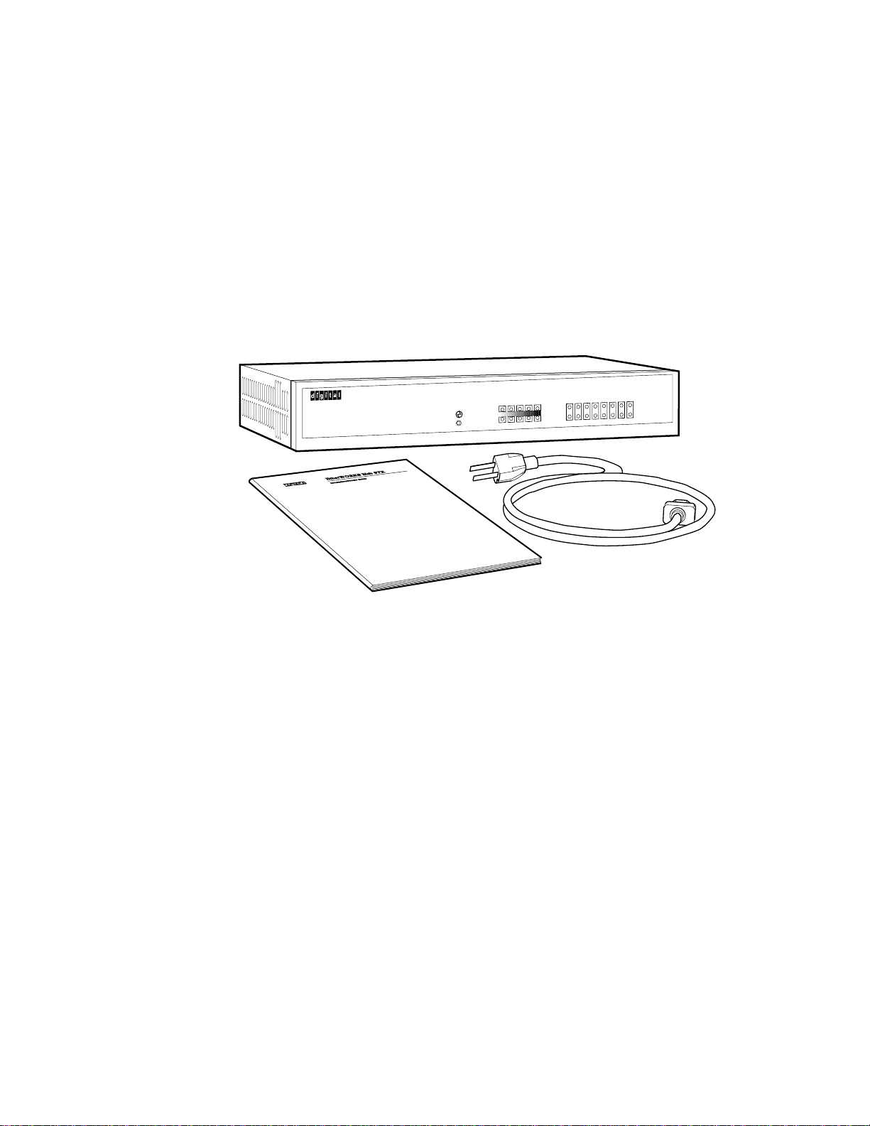
Kit Contents
The EtherWORKS Hub 8TX kit contains the following:
• The EtherWORKS Hub 8TX repeater
• This installation guide
• Power cord (country-specific)
Figure 1 EtherWORKS Hub 8TX Kit Contents
LJ-4795.AI4
Utilization %
Collision % Link/Traffic
Partition
12345678
8
7
6
5
4
3
2
1
13510 15+
65+
30
15
5
1
EtherWORKS Hub 8TX
100 Base TX

Introduction 1–1
Chapter 1
Introduction
Overview
This guide contains information required to install and operate the
EtherWORKS Hub 8TX repeater (hereafter referred to as the Hub 8TX).
The Hub 8TX is a smart 8-port Class II 100BASE-TX repeater that
complies with the IEEE 802.3u standard. The Hub 8TX is used for 100
megabits per second (100-Mb/s) Ethernet networks. It can link two to
eight PCs or workstations using Category 5 unshielded or screened
twisted-pair (UTP or ScTP) cables to form a simple, fast Ethernet LAN.
The Hub 8TX also contains a daisy-chain port to connect to another
compatible repeater using twisted-pair cable.

Features
1–2 Introduction
Features
The main features of the Hub 8TX are as follows:
• Conforms to the IEEE 802.3u repeater specification and the
100BASE-TX standard
•• Transmits data at 100 Mb/s for demanding applications
• LED indicator panel includes utilization and collision rate LEDs
for reporting repeater activity/configuration, and facilitating
problem diagnosis
• Eight independent MJ8 ports for connections using 100BASE-TX
Category 5 UTP or ScTP cable
• One MJ8 port for daisy chaining
•• Automatically partitions bad ports to protect the network system
•• Automatic polarity detection and correction permits automatic
adjustment for wiring errors
• Easy desktop installation
• Internal full-range power supply for 100 VAC to 240 VAC, at 50
to 60 Hz power application
• Cost effective
• Ready to run with all network operating systems and protocols

Hardware Description 2–1
Chapter 2
Hardware Description
Introduction
This chapter briefly describes the important parts of the EtherWORKS
Hub 8TX repeater
Front Panel
2–2 Hardware Description
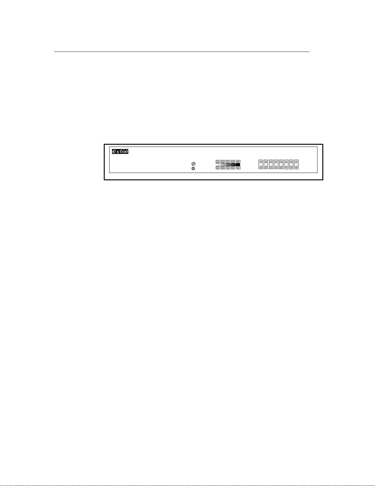
Front Panel
The front panel of the Hub 8TX contains the LED indicators that
monitor various network conditions, such as the status of each station
port or the overall condition of the Hub 8TX (see Figure 2-1). Each
station port contains two LEDs to monitor port link and traffic, or
partition conditions. The overall repeater status relates to power,
network utilization, and collision rate.
Figure 2–1 EtherWORKS Hub 8TX Front Panel
EtherWORKS Hub 8TX
1 5 15 30 65+
15+10
5
3
1
Utilization %
Collision %
Partition
Link/Traffic
1
1
2
2
3
3
4
4
5
5
6
6
8
8
7
7
LJ-4817.AI4
100 Base TX

Front Panel
Hardware Description 2–3
The following table lists and describes the possible LED states for the
Hub 8TX.
Item LED Color Description
1
P
ower
G
reen
L
ights when the repeater
h
as power.
2
U
tilization
G
reen
T
raffic is 1% to 30% of
E
thernet bandwidth
(
100 Mb/s).
Y
ellow
T
raffic is 30% to 65%.
R
ed
T
raffic is 65% or higher.
3
C
ollision
G
reen
C
ollision rate is 1% to 10%.
Y
ellow
C
ollision rate is 10% to
1
5%.
R
ed
C
ollision rate is 15% or
h
igher.
4
P
artition
R
ed
M
J port is partitioned.
5
L
ink/Traffic
G
reen
M
J port linked; flashes to
i
ndicate traffic.
Back Panel
2–4
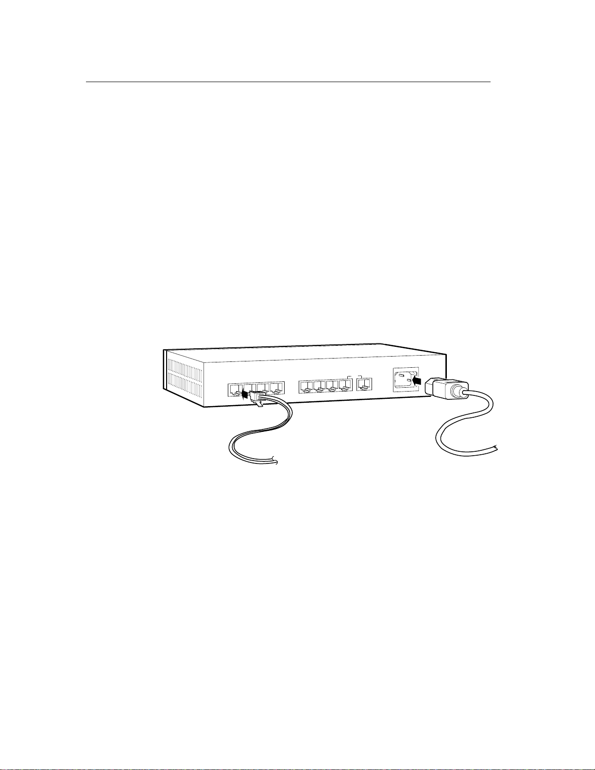
Back Panel
The back panel of the Hub 8TX contains 8 MJ station ports, one
convertible daisy-chain port, and a power socket (see Figure 2-2). Each
station port provides 100 Mb/s Ethernet bandwidth for connection to a
PC, workstation, server, or another compatible repeater (using a
crossover port on the other repeater). A standalone Hub 8TX can link
two to eight systems using Category 5 UTP or ScTP cables to form a
simple fast Ethernet LAN. As your network grows, you can daisy-chain
another 100BASE-TX Class II repeater without using any crossover
cable.
_________________________ Note _________________________
When the daisy-chain port is used, port 8 cannot be connected to
a station.
____________________________________________________________
Figure 2–2 EtherWORKS Hub 8TX Back Panel
LJ-4796.AI4
100-240VAC50-60Hz 0.4A
8//
or
8x
7x
6x
5x
4x
3x
2x
1x
Power Socket
The power socket accepts AC power from 100 V to 240 V at 50 to 60 Hz.

Hardware Installation and Configuration 3–1
Chapter 3
Hardware Installation and Configuration
Overview
This chapter describes how to install and configure the EtherWORKS
Hub 8TX repeater. Once installed, you can configure the Hub 8TX as a
standalone system, or in a network using up to eight systems.

Installation Procedure
3–2 Hardware Installation and Configuration
Installation Procedure
To install the Hub 8TX, complete the following steps:
Step Action
1
S
elect an appropriate table- or desk-top location.
2
C
onnect your system to an available MJ8 port on the Hub 8TX
u
sing Category 5 UTP or ScTP cable. All end-node devices must
b
e within 100 meters of the connected repeater.
3
U
se the MJ8 daisy-chain port to connect the Hub 8TX to
a
nother repeater in a daisy-chain configuration.
4
P
lug the power cable into the repeater, then connect it to an
e
lectrical outlet.
_________________________ Note _________________________
Digital recommends using BN25G-xx (UTP) or BN26M-xx (ScTP)
point-to-point twisted-pair patch cable for connections. The xx
stands for cable length in meters.
____________________________________________________________

Configuration
Hardware Installation and Configuration 3–3
Configuration
The Hub 8TX allows flexibility in configuring your network. You can use
the repeater in a standalone or daisy-chain configuration.
Standalone Configuration
The Hub 8TX can be used in a simple standalone configuration (see
Figure 3-1). In compliance with the IEEE 802.3u standard, the
maximum cable distance between the repeater and any system is 100
meters.
Figure 3–1 Standalone Configuration
LJ-4818.AI4
1x 2x 4x
3x 5x 6x 7x 8x or 8//
100-240VAC 50-60Hz 0.4A

Configuration
3–4 Hardware Installation and Configuration
Daisy-Chain Configuration
The Hub 8TX provides a daisy-chain port (8x or 8//) that you can use to
easily connect to another compatible repeater (see Figure 3-2).
Figure 3–2 Daisy-Chain Configuration
LJ-4799.AI4
1x 2x 4x
3x 5x 6x 7x 8x or 8//
100-240VAC 50-60Hz 0.4A
1x 2x 4x
3x 5x 6x 7x 8x or 8//
100-240VAC 50-60Hz 0.4A
100M
100M
5M

Cable Limitations
Hardware Installation and Configuration 3–5
Cable Limitations
To configure your Hub 8TX network, use the following guidelines to
ensure that the overall length between any two nodes does not
exceed the limits set by the IEEE 802.3u standard:
• The maximum cable length from any repeater port to an end node is
100 meters.
• The maximum cable length between two repeaters should not exceed
5 meters.

This manual suits for next models
1
Table of contents
Other DEC Repeater manuals


