DEC 525-MB User manual

DECpc
525-MB IDE Hard Disk Drive
Installation Guide
EK-XARCG-IA. A01
Digital Equipment Corporation
Maynard, Massachusetts

May 1993
The information in this document is subject to change without notice and should not
be construed as a commitment by Digital Equipment Corporation.
Digital Equipment Corporation assumes no responsibility for any errors that might
appear in this document.
Restricted Rights: Use, duplication, or disclosure by the U.S. Government is subject
to restrictions as set forth in subparagraph (c) (1) (ii) of the Rights in Technical Data
and Computer Software clause at DFARS 252.227-7013.
CopyrightDigital Equipment Corporation.
All Rights Reserved.
Printed in U.S.A.
The following are trademarks of Digital Equipment Corporation:
DEC, DECpc, and the Digital logo.
The following is a third-party trademark:
MS-DOS is a registered trademark of Microsoft Corporation.

Installation Guide
Kit Contents
The 525-MB hard disk drive kit contains the following:
Item Order Number
One disk drive RE25L
Two expansion brackets 74-44337-01
Four screws, #6-32 x 3/16-inch 90-08020-01
Four screws, #6-32 x 1/4-inch 90-00038-19
DECpc 525-MB IDE Hard Disk
Drive Installation Guide EK-XARCG-IA-A01
If you install the drive in a DECpc 400 ST, you need an IDE cable. The cable is not
included with this kit and must be ordered separately. The Digital part number is
BC10N-3E.
Before You Start
Read the following installation instructions. If you are unsure about your ability to
install the drive, you can contact Digital Services to hire a Digital Services technician
to install the drive for you.
If you are replacing a drive, or adding a second drive, always back up the data before
starting the installation.
The drive can be connected directly to the 40-pin IDE-bus connector located on the
DECpc motherboard, or to a separate IDE-bus adapter board.
______________________CAUTION ________________________
Static electricity can destroy the circuits on the drive's circuit
board. Discharge static electricity by touching the drive's metal
frame before touching the circuit board.
1
Installation Guide
Drive Configuration Overview
Drive configuration depends on whether the drive operates as a master or a slave.
If the drive operates as a... Then...
Master (boot drive) Use the factory-default jumper setting
Slave (secondary drive) Reconfigure the jumpers
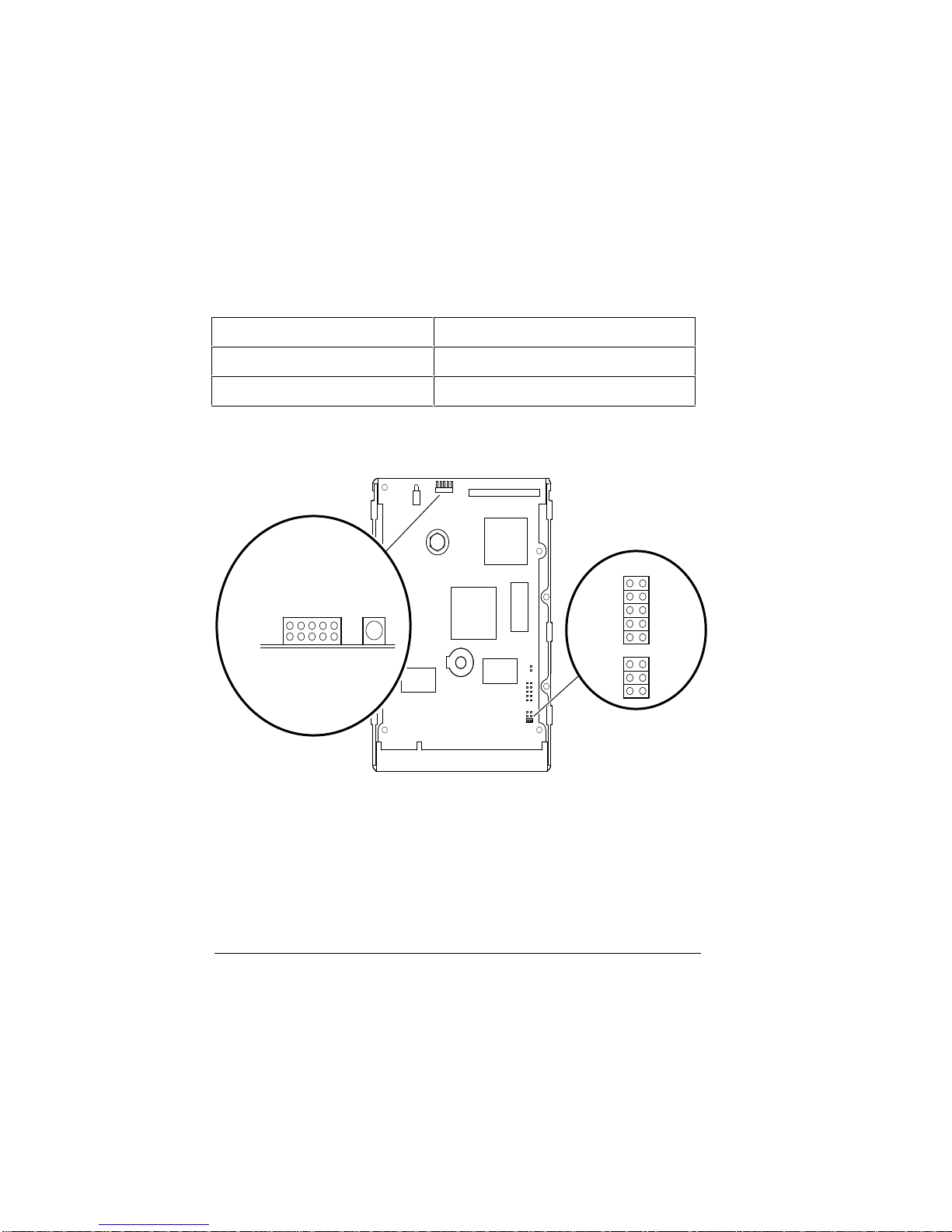
The jumpers are located at J9 and J12 on the printed circuit board (Figure 1).
(Spare)
(No Connection)
SP
DS
SY
LED
PCB
GND
J12 Control Connector
(Side View)
GND
GND
GND
GND
LJ-03046-TI0
Jumpers
J9 DS
SP
SY
CS
SS
Figure 1. Jumper Locations
________________________Note __________________________
Jumpers CS and SY are not applicable to DECpc computers.
Do not change their factory-default settings.
Table 1 describes the J9 and J12 jumper functions and default settings.
2

Installation Guide
Table 1. Jumper Functions and Default Settings
Jumper Function
Default Setting
SS Reserved for factory use
Open *
CS Cable select
Open
SY Synchronization (disk array)
Open
SP Slave present
Open
DS Drive select
Jumpered †
*Only located at J9
† DS jumpered at J9 and DS open at J12
Drive Select (DS) Jumper Configurations
The drive is configured at the factory as a master drive with the DS pins jumpered on
J9. If you install the drive as a slave, park the factory-installed DS jumper.
The DS jumper is a small plastic block that plugs onto a pair of pins. Figure 2 shows
the J9 DS pins both jumpered (master drive) and open/parked (slave drive).
DSSPSY
DSSPSY
LJ-03039-TI0
Jumpered
Open/
Parked
J9
Figure 2. DS Jumper Configurations
3

Installation Guide
You can jumper the DS pins at either the J9 or J12 control connector location.
Example:
If you jumper the DS pins at J12 to configure a master drive, park the jumper (if
installed) on J9.
The drive has drive active slave present (DASP) signal capabilities to check for the
presence of a slave drive. In a master-slave relationship, if both drives have the DASP
option, leave the SP pins at J9 and J12 open. If the slave drive does not have the
option, you must jumper the master drive SP pins.
Table 2 describes the DS jumper settings.
Table 2. DS Jumper Setting Descriptions
Drive Configuration
Setting
Slave drive
DS, Open/parked
SP, Open/parked
Master drive (using the DASP signal to indicate
that a slave drive is present.)
Use this configuration in most cases.
DS, Jumpered (default)
Master drive (using the SP jumper instead of the
DASP signal to indicate that a slave drive is
present.)
DS, Jumpered
SP, Jumpered
Installing the Drive
Perform the following steps to install the drive:
1. Set the correct drive jumper setting for master or slave. See the previous sections
for configuration information.
2. Turn off the computer and unplug the power cord from the wall outlet, then from
the back of the system box.
3. Remove the system box cover and select an available drive bay. See your
computer user guide for instructions.
4
Installation Guide
_______________________ Note _____________________________
Depending on the layout of your computer, you may find it easier to
connect the cables (described in step 5) before you mount the drive
in the bay.
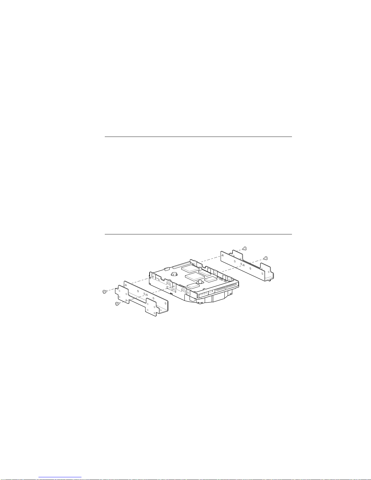
4. Mount the drive in a drive bay. If you mount the drive in a 5¼-inch bay, attach
the expansion brackets (Figure 3).
Some computers require you to install drive rails. If so, attach the drive rails,
supplied with your computer, to the expansion brackets.
_____________________CAUTION___________________________
Use the short (3/16-inch) screws to mount the brackets to the drive.
The longer screws will extend into the circuit board and damage the
drive. Use the longer screws to attach the drive rails to the
expansion brackets, or to mount the brackets to the computer case .
LJ-03040-TI0
Figure 3. Attaching Expansion Brackets
5

Installation Guide
5. Connect the IDE cable and 4-pin DC power cable (Figure 4).
IDE Cable
4-Pin Power Cable
LJ-03041-TI0
Figure 4. Connecting Cables
6. Verify that your computer has an ISA or an EISA bus.
Bus Configuration Utility
ISA (16-bit) System setup utility
EISA (32-bit) System Configuration Utility (SCU)
Run the appropriate setup utility to enter the new drive parameters. See your
computer user guide for the configuration instructions.
7. Select the Hard Drive 1/Hard Drive 2 field in the appropriate setup utility.
Using the following logical addressing parameters (Table 3), you either:
•Select a drive type, from a predetermined list of drives, that matches these
parameters, or
•Enter the parameters as a user-definable hard drive.
6

Installation Guide
Table 3. Logical Addressing Parameters
Size Formatted
Capacity Heads Cylinders Precomp Landing
Zone Sectors
525 MB 525 MB 16 1017 0 0 63
If you select an adapter board instead of the computer's main logic board IDE
hard disk controller, disable the computer's main logic board IDE hard disk
controller. See the setup utilities in your computer user guide.
8. Reboot your computer.
If the operating system is not installed, boot the system with the operating system
installation diskette. See the operating system information for further instructions.
9. Partition and format the drive.
Use these commands with MS-DOS:
•FDISK to partition the drive.
•FORMAT to prepare each partition to receive MS-DOS files.
•FORMAT C: /S to copy the operating system to the primary DOS partition
(master drive partitions only).
See the MS-DOS user information for specific instructions.
10. Restore any backup files.
7

Installation Guide
Specifications
The following table describes operational specifications:
Table 4. Operational Specifications
Characteristics Specifications
Capacity (formatted) 525 MB
Number of disks 3
Number of read/write heads 6
Track density (tracks per inch) 2670
Logical characteristics
•Cylinders
•Heads
•Sectors per track
•Total number of sectors
1017
16
63
1,025,136
Seek times (average)
•Read-on-arrival
•Average write
•Track-to-track
•Full stroke
10 ms
11 ms
< 3 ms
25 ms
Data transfer rate
•Disk to read buffer
•Read buffer to IDE-bus (PIO mode)
2.30–4.66 MB/s
5.00 MB/s
DisCache size 512 KB
Rotational latency (average) 6.7 ms
•Temperature
•Operating
•Nonoperating 0° to 55°C
-40° to 65°C
•Humidity
•Operating
•Nonoperating 8% to 85%
5% to 95%
8
Table of contents
Other DEC Storage manuals


