Decade TRC-800 User manual

HI-FI
STEREO
FMTRANSMITTERS
TRC-800
trRC-800S
INSTRUCTION
MANUAL
( USAversion)
9411-800-S
DECADE
All manuals and user guides at all-guides.com
all-guides.com

TABLEOFCONTENT
SECTION
l: GENERAL
INFORMATIONS
A)Introduction
,
B)Description..
C)
Warranty....
D)Warning.....
E)Technicalspecifications
SECTION
2: TNSTALLATION
A) Introduction
,
B)Receiving
inspection...
C)
Connections.
D)Locationofthe
transmitter
andantenna.
SECTION3: OPERATION
A)Controls
andindicators
B)
Input
and
output
connectors.....
C)Optimal
input
level.
SECTION
4: MAINTENANCE
AND ALIGNMENT
A)Maintenance
B)Frequency
selection..,,.,
C)
RF
power
level
adjustment
D)Bits
switchcodestable.
SECTION
5. APPLICATIONS
ANNEXES
r Adjustments
diagrams
r TRC-800technical
specifications
r TRC-8005
technical
soecifications
PAGE
1
1
1
2
2
4
4
4
3
3
3
5
6
5
o
All manuals and user guides at all-guides.com
A)
SECTION1
GENERALINFORMATIONS
Introduction
Thank
you for purchasing
oneof the fineproducts
made
by DECADE
transmitters.Your new TRC-800 or TRC-800SHl-Fl STEREOFM
TRANSMITTER
is a veryhigh
performance
andhighreliability
piece
of
equipment.Before
using
it,please
read
thismanual
carefullyin orderto
obtain
the best possible
results
from your transmitter.The manual
contains
installation,
operation
andajustements
procedures
for DECADE
TRC-800
(1
Watt)
Hi-Fimono
andTRC-800S
(1
Watt)
of Hi-Fi
Stereo
FM
Transmitters.
Description
TRc-800
andrRC-800S
transmitters
include
a crystal
controlledVCo,a
stereo
generator
(TRC-800S
only),
a RF
power
amplifier
and
a spurious
filter.Theyaccept
leftand right
audiosignals
on two types
of input
connectors:
I XLR3
600 Ohmsbalanced
inputs,
withsignallevels
ranging
from
-1
5
dBmmin.
to +22 dBmmax.;
I 114"
10K
ohmsunbalanced
inputs,
with
signallevelsranging
from
-15
dBmmin.
to +39 dBm
(70
VRMS)
max.
lnputlevel
canbe ajustedfrom
the INPUTLEVEL
control
on thefront
panel,
inorder
to get
theoptimum
modulation
level.
That
usefulfeature
makes
DECADE
transmittersvery versatile,
allowing
them to accept
audio
signalsfrom
many
sources:
cD players,
tape
decks,mixing
boards,
cinema
projectors,
etc.
Warranty
TRc-800
andrRC-800S
tranmitters
comewith a two (2)
years
warranty
thatcovers
parts
replacement
andlabor
required
to repair
anydefects
resulting
from
themanufacturing
process.
All
claimsmust
beauthorised
by DECADE
prior
to shipment
of a faulty
unitfor repairs
anda copyof
the
invoice
must
beincluded
in
the
shipment.
Shipingfees
areassumed
by
the
clientandDECADE
will
pay
for
thereturn
ofthe
repaired
unit.
B)
U]
All manuals and user guides at all-guides.com

D) Warning
DECADE
transmittersoperateonthe87.9MHz
- 107.9
MHZ
commercial
FMbroadcastband,sosignals
transmittedby themcanbereceived
on
anystandard
FMreceiver.Thus,
somecareshould
betakenin the use
made
outof
thesetransmitters.
DECADE
transmitters
inc.isnotresponsible
foranyloss
of profit
or laws
violation
duringtheutilisationof
theirtransmitters.
The CRTC (Canadian Radio-television
and Telecommunications
Commission)andthe DOC
(Department
Of Communications,
Canada)
legislate
theuseof FM
transmitters.Nolicence
isrequiredforindoor
use
ofthesetranmitters,aslong
as
thetransmitted
signal
ismostly
contained
inthebuildingintended
to becovered
bythe
transmitter
(ex.:
a concert
hall,
a church,
a theatre,etc.)Formost
applications,
a RF
power
level
from1 to 5 mWattsis
sufficientfor indoor
uses.
There
isa simple
test
thatcanbe performed
to verify
if the power
level
is adequate:with a
walkman
tuned
to the transmitter
frequency,
check
if the reception
is
good
everywhere
in the hall,
with no deadspots
(distortion,
noise
or
weakreception),
Then,
go outside
of the building
andmake
the same
verification,
except
thatthis
time,
youmust
have
bad
reception
(or
no
reception
atall)
around
thebuilding,wich
means
that
power
level
isnot
too
high
and
thusadequate
forindoor
use.lfyou
still
getgood
reception
outside
the building,
youwillhave
to lower
the RF
power
level
of the
transmitter
(refer
tomaintenance
andalignement,
section4).
For
outdoor
uses
CRTChasreleased
many
public
notices
on low power
FM
transmitters,
allowing
their
use
in
specific
applications
such
as:
I drive-in
theatres;
r private
touristicand
attraction
siteswith
admissionfees;
I special
events
coveragenot exceeding
28 consecutives
daysin
duration;
r any
application
operating
under
theCRT-74regulations,
wich
allows
a tranmittingrange
of about
200 to 600 feet,
depending
on the
type
ofreceiver
used.
REFERENCES: public
notices
CRTC1993-45,
CRTC
1993-95
and
CRTC1990-1
11.
Technical
specifications
Refer
toannexes,
Technical
specifications
ofrRC-800
and
rRc-800s.
FI
All manuals and user guides at all-guides.com

A)
sEcTtoN
2
INSTALLATION
Introduction
Installation
of aDECADE
FM
transmitter
includes
the
following
steps: 1)
receivinginspection;
2)mountingina rackorona shelf;3)connection
of the
ACsupplyand
audio
source;
location,installationandconnection
ofthe
antenna.
Receivinginspection
Checkthe transmitter
packaging
for any damagethat could have
occured
in
theshiping.
lf you
find
any
damage
on
thetransmitter,
keep
the packaging
for claiming
purposes
with the freightcompany.Any
damageshouldbe
noted
onthe
receiving
slipatthetimeofdeliveryand
the freight
company
advised
within 5 workable
days following
the
deliveryofdamagedunits.
Connections
After
installation
of thetransmitter
ina rack
or on a shelf,
plug
theAC
cable
inthe
AC receptacle
ontheback
panel,
andconnect
to a 12OV,
60 Hz
grounded
ACsocket.As withany
grounded
electricequipement,
it isnot
recommended
to use
a DECADE
transmitter
without
a grounded
AC socket,or removing
thegrouding
pin
on thecable,
sincethat
may
resultin
shock
hazardsfor
thestaff
in
contactwithit.
Location
ofthetransmitterandantenna
DECADE
transmitters
aredesigned
for indoor
or outdoorusein a dry
environment,in temperatures
ranging
from -20 to 60 'C. In orderto
obtainoptimum
performances,
itis
recommended
to place
them
farfrom
anyelectromagnetic
noisesource
(transformers,
motors,
etc.).
Antenna
shouldbe
located
ascloseto the
centerof the
hall
orcoverage
area
as
possible,
and
ata sufficient
height
to give
thetransmitted
signal
aunobstructed
path
to everyseatorreceiving
point.
Concrete
walls
and
steel
beam
orsheets
greatly
attenuate
radio
waves,soavoidto have
the
transmitted
signal
path
going
through
them,Onthe
otherhand,
windows
arevery
permeable
to radiowaves,
so avoidlocatingthe antenna
near
themif
you
wish
to restrain
thecoverage
tothe
interiorofa building.
B)
a\
D)
All manuals and user guides at all-guides.com

A)
sEcTtoN3
OPERATION
Controls
and
indicators
TRC-800
and
TRC-800S:Input
level
is
controledbya
stereo
(TRC-800S)
potentiometer,
labeledINPUTLEVEL
and
located
onthe
front
panel.
One
ledindicates
the
modulationlevel:OVER
(red),
wich lightsup when
the
modulation
levelis equalor greater
than 2OOo/o,wich indicates
an
overmodulationstate
and
could
resultin distortionat thereceiving
end,
The OVER
indicatorshouldnever
or rarelylight,in order
to avoid
distortion.
Toallowa better
perception
of this
indicator,itsholding
time
hasbeen
lenghtened,
becauseof its
importance.
The
TRC-800S
transmitter
canbe
switched
frommono
to stereo
mode,
in
orderto let
you
usethebest
mode
for
yourparticular
application.
The
stereoselector
islocated
onthe
front
panel.
Whenin stereo
mode,
the
STEREO
indicatorlights
up, In mono,
onlythe RIGHTinput
is active
(balanced
orunbalanced)and
the
LEFTinputisignored.
Input
andoutputconnectors
TRC-800
and TRC-800S
transmitterscome with two sets of inputs:
RIGHT
and LEFTXLR3 balancedinputs
and RIGHTand LEFT114"
unbalanced
inputs,wich are the two most popular
types of input
connectors.
The RF outputhas a female
UHF (PL)
connectorand typicalload
impedance
is 50 Ohms.
Antenna
cable
(RG-8
or RG-58)
shouldnor
exceed200 feetin lenghtf
or RG-8
and
100feet
for RG-58,inorderto
minimise
the
power
lossin
thecable.
Optimal
input
level
Optimal
inputlevel
is reachedwhen the OVER
modulationindicator
remains
offmost
ofthetime.Adjust
the
inputlevel
controlto meet
that
condition,
R\
a\
A
All manuals and user guides at all-guides.com
all-guides.com

lB qz&- 323
L-/ -::, --l -)>
MAINTENANCE
AND ALIGNMENT
A) Maintenance
No maintenance
is required
to keep
the transmitter
in top operating
condition.
lf anexternalcleaningappears
neccessary,
usea soft,damp
clothand
mild
soaponly,
Frequency
selection
The
transmitting
frequencyis
programmed
atthe
factory.lf a changeof
the
frequencywas
required,follow
thesesteps:
1
) from
the<bits
switch>codestable,on the next
pages,
select
the
appropriate
<bits
switch>codefor your
chosenfrequency
andset
the <bits
switch,,on the main boardaccordingly.
Refer
to the
,,adjustments
diagrams>attheendofthe
manualfor
the
location
of
the
<bits
switch>.
Connect a DC voltmeter
to the alligator
clips, with the positive
terminal
(+, red)
of the voltmeter
on the red
alligatorclip
andthe
negative
terminal
(-, black)of the voltmeter
on the black alligator
clip.
Selectthe 20 VDCscaleon the
voltmeter.
Using
a small,
non-conductive
flat screw-driver,turn the COARSE
tuningadjustmentof the VCO
until
you read
between0.5 and7.5
volts,Then
turn the FINE
tuningadjustmentuntil
you get a reading
between 3.0 and 5.0 volts. Your transmitteris now stabilisedon
theselected
frequency.
RF
power
level
adjustment
A smallwhite
trimpot
labeledPOWER
(PWR)
and
locatednear
the<bits
switch>is usedto controlthe RF
power
level
of thetransmitter.
Turn
clockwise
to increaseRF
power
level
andcounterclockwise
to decrease
rt,
B)
2)
3)
All manuals and user guides at all-guides.com

D) Bitsswitch
codestable
Freq
(MHz) 110
9
8
7
o
5
43
2
87.9
88.1
BB.3
BB.5
BB.7
ON OFF OFF ON OFF OFF ON OFF OFF OFF
ON OFF OFF ON OFF OFF OFF ON ON ON
ON OFF OFF ON OFF OFF OFF ON ON OFF
ON OFF OFF ON OFF OFF OFF ON OFF ON
ON OFF OFF ON OFF OFF OFF ON OFF OFF
BB.9
89.1
89.3
89.5
89.7
ON OFF OFF ON OFF OFF OFF OFF ON ON
ON OFF OFF ON OFF OFF OFF OFF ON OFF
ON OFF OFF ON OFF OFF OFF OFF OFF ON
ON OFF OFF ON OFF OFF OFF OFF OFF OFF
ON OFF OFF OFF ON ON ON ON ON ON
89.9
90.1
90.3
90.5
90.7
ON OFF OFF OFF ON ON ON ON ON OFF
ON OFF OFF OFF ON ON ON ON OFF ON
ON OFF OFF OFF ON ON ON ON OFF OFF
ON OFF OFF OFF ON ON ON OFF ON ON
ON OFF OFF OFF ON ON ON OFF ON OFF
90.9
91.1
91.3
91.5
91
.7
ON OFF OFF OFF ON ON ON OFF OFF ON
ON OFF OFF OFF ON ON ON OFF OFF OFF
ON OFF OFF OFF ON ON OFF ON ON ON
ON OFF OFF OFF ON ON OFF ON ON OFF
ON OFF OFF OFF ON ON OFF ON OFF ON
91
9
92.1
92.3
92.5
92.7
ON OFF OFF OFF ON ON OFF ON OFF OFF
ON OFF OFF OFF ON ON OFF OFF ON ON
ON OFF OFF OFF ON ON OFF OFF ON OFF
ON OFF OFF OFF ON ON OFF OFF OFF ON
ON OFF OFF OFF ON ON OFF OFF OFF OFF
92.9
93.1
93.3
93.5
93.7
ON OFF OFF OFF ON OFF ON ON ON ON
ON OFF OFF OFF ON OFF ON ON ON OFF
ON OFF OFF OFF ON OFF ON ON OFF ON
ON OFF OFF OFF ON OFF ON ON OFF OFF
ON OFF OFF OFF ON OFF ON OFF ON ON
93.9
oA1
94.3
94.5
94.7
ON OFF OFF OFF ON OFF ON OFF ON OFF
ON OFF OFF OFF ON OFF ON OFF OFF ON
ON OFF OFF OFF ON OFF ON OFF OFF OFF
ON OFF OFF OFF ON OFF OFF ON ON ON
ON OFF OFF OFF ON OFF OFF ON ON OFF
94.9
95 1
953
95.5
957
ON OFF OFF OFF ON OFF OFF ON OFF ON
ON OFF OFF OFF ON OFF OFF ON OFF OFF
ON OFF OFF OFF ON OFF OFF OFF ON ON
ON OFF OFF OFF ON OFF OFF OFF ON OFF
ON OFF OFF OFF ON OFF OFF OFF OFF ON
I5.9
96.1
963
96.5
96.7
ON OFF OFF OFF ON OFF OFF OFF OFF OFF
ON OFF OFF OFF OFF ON ON ON ON ON
ON OFF OFF OFF OFF ON ON ON ON OFF
ON OFF OFF OFF OFF ON ON ON OFF ON
ON OFF OFF OFF OFF ON ON ON OFF OFF
96.9
97.1
97.3
97.5
97.-I
ON OFF OFF OFF OFF ON ON OFF ON ON
ON OFF OFF OFF OFF ON ON OFF ON OFF
ON OFF OFF OFF OFF ON ON OFF OFF ON
ON OFF OFF OFF OFF ON ON OFF OFF OFF
ON OFF OFF OFF OFF ON OFF ON ON ON
All manuals and user guides at all-guides.com

Freq.
(MHz) 1 z 510
9B
7o
4
97.9
98.1
98.3
98.5
oa7
ON OFF OFF OFF OFF ON OFF ON ON OFF
ON OFF OFF OFF OFF ON OFF ON OFF ON
ON OFF OFF OFF OFF ON OFF ON OFF OFF
ON OFF OFF OFF OFF ON OFF OFF ON ON
ON OFF OFF OFF OFF ON OFF OFF ON OFF
98.9
99.1
99.3
99.5
99.7
ON OFF OFF OFF OFF ON OFF OFF OFF ON
ON OFF OFF OFF OFF ON OFF OFF OFF OFF
ON OFF OFF OFF OFF OFF ON ON ON ON
ON OFF OFF OFF OFF OFF ON ON ON OFF
ON OFF OFF OFF OFF OFF ON ON OFF ON
99.9
1
00.1
100.3
1
00.5
1007
ON OFF OFF OFF OFF OFF ON ON OFF OFF
ON OFF OFF OFF OFF OFF ON OFF ON ON
ON OFF OFF OFF OFF OFF ON OFF ON OFF
ON OFF OFF OFF OFF OFF ON OFF OFF ON
ON OFF OFF OFF OFF OFF ON OFF OFF OFF
100.9
101
.1
101.3
101.5
101.7
ON OFF OFF OFF OFF OFF OFF ON ON ON
ON OFF OFF OFF OFF OFF OFF ON ON OFF
ON OFF OFF OFF OFF OFF OFF ON OFF ON
ON OFF OFF OFF OFF OFF OFF ON OFF OFF
ON OFF OFF OFF OFF OFF OFF OFF ON ON
101
.9
102.1
102.3
102
5
102.7
ON OFF OFF OFF OFF OFF OFF OFF ON OFF
ON OFF OFF OFF OFF OFF OFF OFF OFF ON
ON OFF OFF OFF OFF OFF OFF OFF OFF OFF
OFF ON ON ON ON ON ON ON ON ON
OFF ON ON ON ON ON ON ON ON OFF
1
02.9
1
03.1
103.3
1
03.5
103.7
OFF ON ON ON ON ON ON ON OFF ON
OFF ON ON ON ON ON ON ON OFF OFF
OFF ON ON ON ON ON ON OFF ON ON
OFF ON ON ON ON ON ON OFF ON OFF
OFF ON ON ON ON ON ON OFF OFF ON
103.9
104,1
1
04.3
1
04.5
104.7
OFF ON ON ON ON ON ON OFF OFF OFF
OFF ON ON ON ON ON OFF ON ON ON
OFF ON ON ON ON ON OFF ON ON OFF
OFF ON ON ON ON ON OFF ON OFF ON
OFF ON ON ON ON ON OFF ON OFF OFF
1
04.9
105.1
105.3
1
05.5
1
05.7
OFF ON ON ON ON ON OFF OFF ON ON
OFF ON ON ON ON ON OFF OFF ON OFF
OFF ON ON ON ON ON OFF OFF OFF ON
OFF ON ON ON ON ON OFF OFF OFF OFF
OFF ON ON ON ON OFF ON ON ON ON
1
05.9
1
06.1
IUb.J
1
06.5
106.7
OFF ON ON ON ON OFF ON ON ON OFF
OFF ON ON ON ON OFF ON ON OFF ON
OFF ON ON ON ON OFF ON ON OFF OFF
OFF ON ON ON ON OFF ON OFF ON ON
OFF ON ON ON ON OFF ON OFF ON OFF
106.9
107.1
107.3
107.5
107.7
107.9
OFF ON ON ON ON OFF ON OFF OFF ON
OFF ON ON ON ON OFF ON OFF OFF OFF
OFF ON ON ON ON OFF OFF ON ON ON
OFF ON ON ON ON OFF OFF ON ON OFF
OFF ON ON ON ON OFF OFF ON OFF ON
OFF ON ON ON ON OFF OFF ON OFF OFF
7
I
All manuals and user guides at all-guides.com
sEcTtoN5
APPLICATIONS
TheTRC-800
or
TRC-800-Smodelsare
certifiedunder
FCC
Part73 regulations.
A license
orexperimental
licenseisrequired
for
operationofsuchFM
transmitters
in
USA.
Pleasecontact
your
nearestFCC
bureauformore
details,
All manuals and user guides at all-guides.com
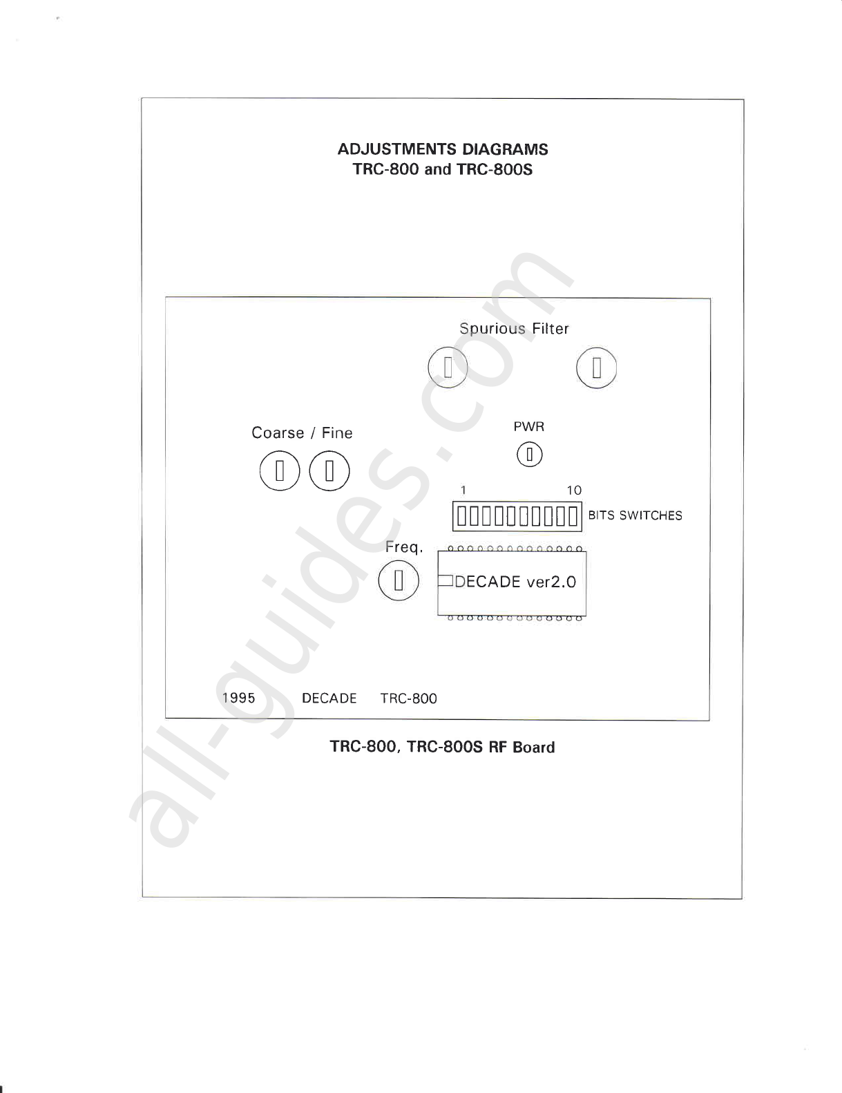
ADJUSTMENTS
DIAGRAMS
TRC-800
and
TRC-800S
TRC-800,
TRC-800S
RF
Board
purious
Filter
Coarse/ Fine PWR
@
@@ 10
mmmtml
BITS
SWITCHES
ECADE
ver2.O
1
995 DECADE TRC-8OO
Freq.
All manuals and user guides at all-guides.com
all-guides.com
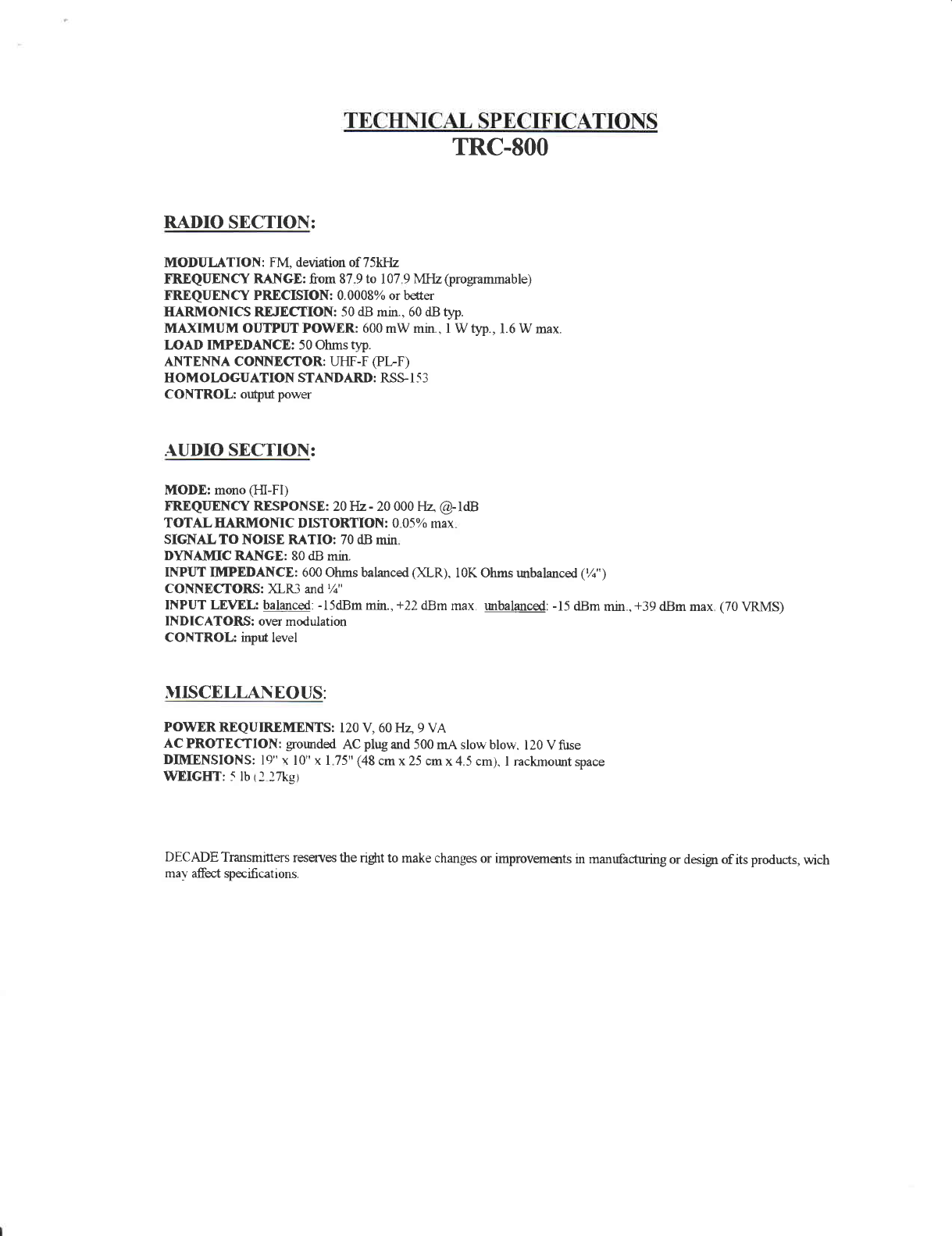
TRC.SOO
RADIO SICTION:
MODIILATION: FM,deviationof75WIz
FREQIIENCY RANGE:from879to 107
9MI{z (programmable)
FREQITENCYPRDCISION:0.0008%orbder
HARMONICSREIECTION: 50
dB
mrn.,60dBtlip.
MAXIMUM OUTPUTPOWER:600mWmin.,
I Wtyp.,
l.6Wmax.
L/OADIMPEDANCE: 50Ohms
typ.
AI\TEI{NA COI{NEC:TOR:UHF-F
(PLF)
HOMOLOGUATION STAIT{DARD:RSSI53
CONTROL:
offptf power
ATJDIOSECTION:
MODE: mono(HI-FI)
FRDQUENCY RLSPONSE:20Ifz-20 000FIz @-ldB
TOTALHARMONIC DISTORTION: 0 05% max
SIGNALTO NOISE RATIO: 70dB min
DYNAMIC RANGE: 80dB min.
INPUT IMPEDAI{CE: 600Ohmsbalanced
Ofl-R), l0K OhmsrmbalancdC/;')
CONNECTORS: )fl-R3 and %"
INPUT LEVEL: balanced:
-l5dBm min.,+22dBm max urbalanced:
-15dBm min ,+39 dBm max (70VRMS)
INDICATORS: overmodulation
CONTROL: inpd level
}IISCELI.ANEOUS:
POWDRREQUIREMENTS:
120V, 60Hz 9VA
ACPROTECTION:
grornded
AC
plryand500
mAslowblow.
120Vflrse
DIMENSIONS:
19"
r 10"r I 75"(48
cmx25cmx45cm).I rackmount
space
WEIGHT:5lb
tl lniet
DECADE Transmiters reservesthe right to makechanges
or improvemantsurmanrfacturing or designof its products,wich
mav afect qpecifi
cat
ions.
All manuals and user guides at all-guides.com
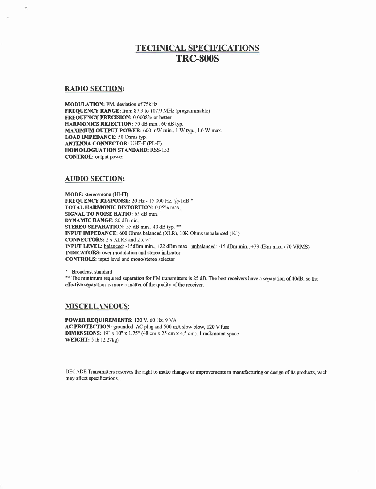
TE
CHIICAL SPECIF'ICATIONS
TRC-8OOS
R{DIO SECTION:
MODUIITION: FM,deviationof75kHz
FR"EQT
ENCYRANGE:from
879to 107
9MFIz
(programmable)
FR"EQUENCYPRECISION:
000o8ooorbder
HARI}IOIIIICSREIECTION: 50dBmm,60dBt)".
I}IAXIMIIM OUIPUT POWER 600mWmin.,I Wtyp.,1.6W max.
IOAD IMPEDAI\CE: 50
Ohmstyp.
ANTENNA COI\II\IECTORUIIF-F(PL-F)
HOMOL/OGUATION
STAITTDARD:RS$153
CONTROL: otspttr
po\\€r
AUDIO SECTION:
MODE : serecr'mono(III-FI)
FRIQUENCY RLSPONSE:20LIz- l5 000FIz @!ldB *
TOTAL EARMOIIIIC DISTORTION: 0 05oomar
SIGNALTO NOISE RATIO: 65dB mm
DYNAMIC RANGE: 80dB mrn
STEREO SEPARATION: 3-<dB mm..-10
dB qT **
II\aPUT
IMPEDAITICE: 600Ohmsbalanced
QOR), lOK Ohmsurbalancd(Vn")
COI{NECTORS: 2 r \l-R3 and2 x /a"
INPUTLEVEL: balanced:
-l5dBmmin.,+22dBmmax. mbalanced:
-15
dBmmin.,+39dBmmax (70VRMS)
INDICATORS: over modulation andstereoindicator
CONTROIS: inpd level andmono/stereoselector
' Broadcaststandard
** Theminimum reqruredseparationfor FM transmitters is 25 dB. The bestreceivershavea s?aration of 40dB, sothe
efective separationis more a maffer ofthe quality ofthe receiver.
MISCELL{I{EOUS:
POWERREQUIR-EMENTS:120V,60Flz9VA
ACPROTECTION:
gromded
AC
plug
and500
mAslowblow,
120Vfirse
DIMENSIONS:
l9"r l0"x 1.75"(48cmr25cmx45 cm).
lrackmourtspace
WEIGHT: 5lb12
lnig)
DEC.f'DE
Transmisers
reserves0terighttomakechangesorimprovemerts
inmanrtractmingordesigr
ofitsproducts,
wich
maraffbct
specifications
All manuals and user guides at all-guides.com

DECADETRANSNIITTERSINC.
@UPDATE E
Iru/ry14,1997
RF POWER LEVEL AND PROGAMMATION
OFTRC-8OO
RF POWER LEVEL
If youwsh to increase
or decreasetheRFpower,
it is mandatory
to check
out
the
DC roltage
(aligator
clips)to make
shurethat
theoscillatoris in it's
capture
zone
(3to.lvolts
DC).Pleaserefertofrequency
selection,
sectionI and2.
}IO\ITORINC
N.B.: We strongly suggest
to let the watt meter plugged in
permanence
between
theoutput of the transmitter and the
transmissionline to assurea good monitoring of the
completesystem.
The
SWR-1-l
uattmeter
isavailable
from
DECADB TRANSN{TTTBRS.
Bestregard.
Sylvain
Couture
Director
ofproduction
All manuals and user guides at all-guides.com
Other manuals for TRC-800
1
This manual suits for next models
1
Table of contents
Other Decade Transmitter manuals


Popular Transmitter manuals by other brands


Michell Instruments
Michell Instruments SF72 user manual

B-Speech
B-Speech TX4 Instruction manual and warranty information

M-system
M-system Mini-M M2VT instruction manual

Lectrosonics
Lectrosonics M175 quick start guide

Emerson
Emerson Rosemount 3100 Series Reference manual

Extron electronics
Extron electronics XTP T HWP 101 4K user guide


