Decagon EC-5 User manual

Operator’s Manual
Decagon Devices, Inc.
Version: October 10, 2016 — 11:23:43

EC-5
Decagon Devices, Inc.
2365 NE Hopkins Court
Pullman WA 99163
Phone: 509-332-5600
Fax: 509-332-5158
Website: www.decagon.com
Trademarks
“ECH2O” is a registered trademark of Decagon Devices, Inc.
c
2001-2014 Decagon Devices, Inc.
All Rights Reserved
ii

EC-5 CONTENTS
Contents
1 Introduction 1
1.1 Warranty ......................... 1
1.2 Seller’s Liability . . . . . . . . . . . . . . . . . . . . . . 2
2 About EC-5 3
2.1 Specifications ....................... 3
3 Installing the Sensors 5
3.1 Wiring........................... 6
4 Connecting Sensors 9
5 Collecting Data 10
5.1 Data Logger Requirements . . . . . . . . . . . . . . . . 10
5.2 Sample Program . . . . . . . . . . . . . . . . . . . . . 10
5.3 SCWin (Short Cut) Directions . . . . . . . . . . . . . 11
5.4 Removing the Sensor . . . . . . . . . . . . . . . . . . . 13
6 Calibration 14
6.1 Sensor Calibration Values . . . . . . . . . . . . . . . . 14
7 Maintenance and Troubleshooting 17
8 Declaration of Conformity 18
iii

EC-5 1 INTRODUCTION
1 Introduction
Thank you for choosing Decagon’s EC-5 Volumetric Water Content
sensor. This manual can help you understand the sensor features and
ensure successful sensor operation. We hope you find the contents of
this manual useful in understanding your instrument and maximiz-
ing its benefit to you.
There are several ways to contact Decagon if you ever need assis-
tance with your product, have any questions, or feedback. Decagon
has Customer Service Representatives available to speak with you
Monday through Friday, between 7am and 5pm Pacific time.
Note: If you purchased your sensor through a distributor, please con-
tact them for assistance.
Email:
Phone:
509-332-5600
Fax:
509-332-5158
If contacting us by email or fax, please include as part of your mes-
sage your instrument serial number, your name, address, phone, fax
number, and a description of your problem or question.
Please read these instructions before operating your sensor to en-
sure that it performs to its full potential.
1.1 Warranty
The sensor has a 30-day satisfaction guarantee and a one-year war-
ranty on parts and labor. Your warranty automatically validates
upon receipt of the instrument.
1

1 INTRODUCTION EC-5
1.2 Seller’s Liability
Seller warrants new equipment of its own manufacture against de-
fective workmanship and materials for a period of one year from the
date of receipt of equipment.
Note: We do not consider the results of ordinary wear and tear,
neglect, misuse, accident as defects.
The Seller’s liability for defective parts shall in no event exceed the
furnishing of replacement parts “freight on board” the factory where
originally manufactured. Material and equipment covered hereby
which is not manufactured by Seller shall be covered only by the
warranty of its manufacturer. Seller shall not be liable to Buyer for
loss, damage or injuries to persons (including death), or to property
or things of whatsoever kind (including, but not without limitation,
loss of anticipated profits), occasioned by or arising out of the instal-
lation, operation, use, misuse, nonuse, repair, or replacement of said
material and equipment, or out of the use of any method or process
for which the same may be employed. The use of this equipment con-
stitutes Buyer’s acceptance of the terms set forth in this warranty.
There are no understandings, representations, or warranties of any
kind, express, implied, statutory or otherwise (including, but with-
out limitation, the implied warranties of merchantability and fitness
for a particular purpose), not expressly set forth herein.
2

EC-5 2 ABOUT EC-5
2 About EC-5
The EC-5 determines volumetric Water Content (VWC) by measur-
ing the dielectric constant of the media using capacitance and fre-
quency domain technology. The 70 MHz frequency minimizes salinity
and textural effects, making this sensor accurate in almost any soil
or soilless media. It arrives with factory calibration for mineral soils,
potting soils, rockwool, and perlite included in this Operator’s Man-
ual.
The two-prong design and higher measurement frequency allows the
EC-5 to measure VWC from 0 to 100% (VWC of saturated soils is
generally 40 to 60% depending on the soil type) and allows accurate
measurement of all soils and soilless medias with a wide range of
salinities.
2.1 Specifications
Measurement Time: 10 ms (milliseconds)
Accuracy: at least 0.03 m3/m3typical soils, up to 8 dS/m
With soil-specific calibration: ±.02 m3/m3(±2%)
Resolution: 0.001 m3/m3VWC in mineral soils, 0.25% in growing
media
Power Requirements: 2.5 VDC to 3.6 VDC @ 10 mA
Output: 10 to 40% of excitation voltage (250 to 1,000 mV at 2,500
mV excitation)
Operating Environment: -40 to 50 ◦C1
Range of Measurement: 0 to 100%
Sensor dimensions: 8.9 cm ×1.8 cm ×0.7 cm
Connector Types: 3.5 mm (stereo) plug or stripped & tinned lead
wires (Pigtail)
1Sensors can be used at higher temperatures under certain conditions. Please
contact Decagon for assistance.
3

2 ABOUT EC-5 EC-5
Cable Length: 5 m standard; custom cable lengths up to 40 m
available upon request
Data logger Compatibility (not exclusive):
•Decagon: Em50, Em50R, and Em50G
•Campbell Scientific: Any logger with serial I/O (CR10X,
CR850, 1000, 3000, etc.)
4

EC-5 3 INSTALLING THE SENSORS
3 Installing the Sensors
When selecting a site for installation, it is important to remember
that the soil adjacent to the sensor surface has the strongest influ-
ence on the sensor reading and that the sensor measures the VWC.
Therefore any air gaps or excessive soil compaction around the sen-
sor can profoundly influence the readings. Also, do not install the
sensors adjacent to large metal objects such as metal poles or stakes.
This can attenuate the sensors electromagnetic field and adversely af-
fect output readings. Because the EC-5 has gaps between its prongs,
it is also important to consider the size of the media you are insert-
ing the sensor into. It is possible to get sticks, bark, roots or other
material stuck between the sensor prongs, which will adversely affect
readings. Finally, be careful when inserting the sensors into dense
soil, as the prongs will break if excessive sideways force is used when
pushing them in.
Installation Procedure
When installing the EC-5, it is best to maximize contact between
the sensor and the soil.
•If you are installing sensors in a lightning prone area with
a grounded data logger, please see our Application Note at
www.decagon.com/lightning.
•Decagon advises that you test the sensors with your data log-
ging device and software before going to the field.
The EC-5 sensor was designed for easy installation into the soil. Af-
ter digging a hole to the desired depth, push the prongs on the sensor
into undisturbed soil at the bottom of the hole or into the sidewall
of the hole. Make sure that the prongs and black overmolding are
buried completely. Note: The sensor may be difficult to insert into
extremely compact or dry soil. If you have difficulty inserting the
sensor, try loosening the soil somewhat or wetting the soil. Never
pound the sensor into the soil
Carefully backfill the hole to match the bulk density of the surround-
5
3 INSTALLING THE SENSORS EC-5
ing soil. Be careful not to bend the black overmolding connecting the
sensor to the cable.
To watch a video on proper installation of the sensor go to
www.decagon.com/install.
Orientation
The sensor can be oriented in any direction. However, orienting
the flat side perpendicular to the surface of the soil will minimize
effects on downward water movement.
Removing the Sensor
When removing the sensor from the soil, do not pull it out of the soil
by the cable! Doing so may break internal connections and make the
sensor unusable.
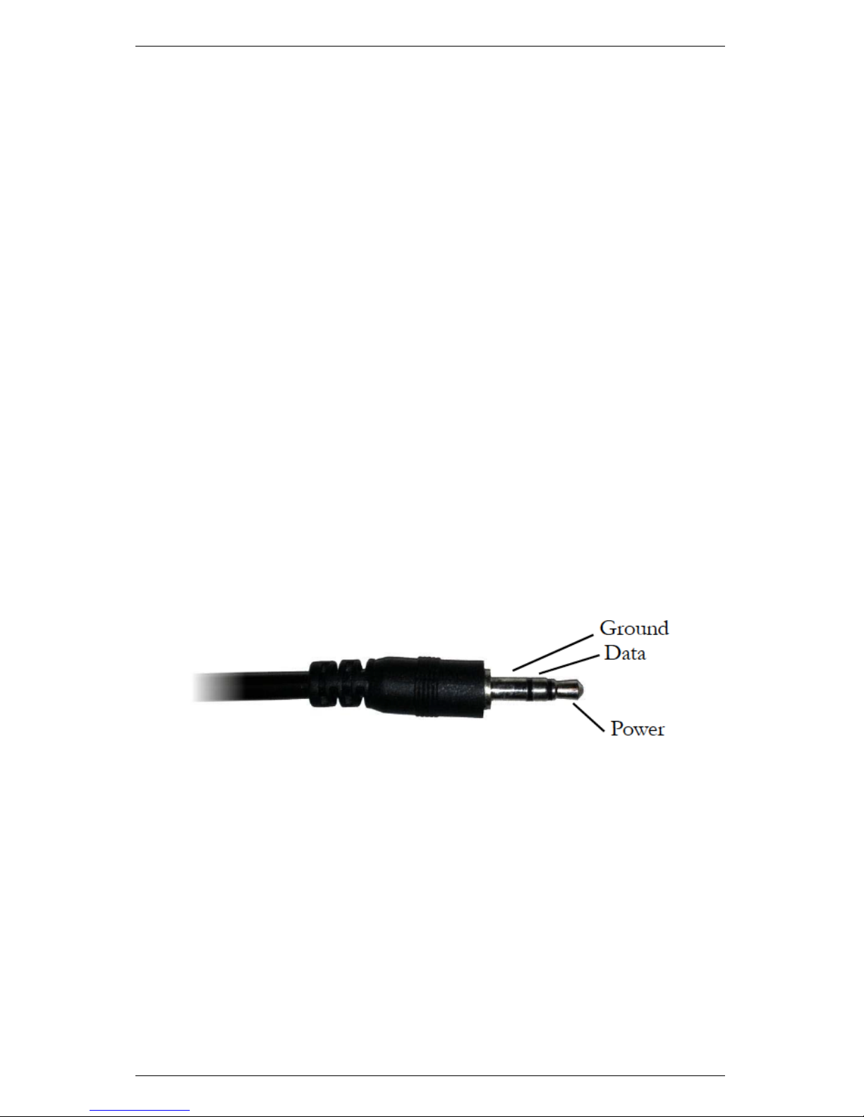
3.1 Wiring
Figure 1: 3.5 mm Stereo Plug
The following software support the EC-5 sensor:
•ECH2O Utility 1.12 or greater
•ECH2O DataTrac 2.77 or greater
Connecting to a non-Decagon Logger
Customers may purchase EC-5 sensors for use with non-Decagon
6
EC-5 3 INSTALLING THE SENSORS
data loggers. These sensors typically come configured with stripped
and tinned (pigtail) lead wires for use with screw terminals. Refer to
your distinct logger manual for details on wiring. Our Integrator’s
Guide gives detailed instructions on connecting the EC-5 sensor to
non-Decagon loggers. Please visit www.decagon.com/support/literat
ure for the complete Integrator’s Guide.
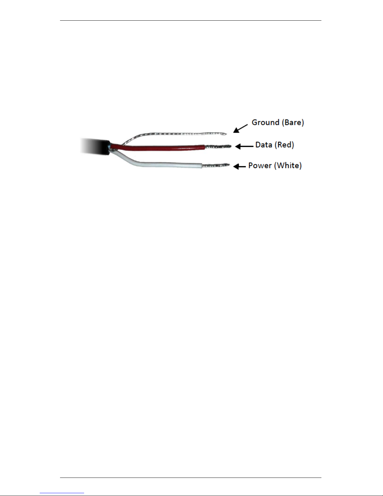
Figure 2: Pigtail End Wiring
Pigtail End Wiring
Connect the wires to the data logger as Figure 3 shows, with the
supply wire (white) connected to the excitation, the analog out wire
(red) to a analog input, the bare ground wire to ground as illustrated
in Figure 2.
Note: The acceptable range of excitation voltages is from 2.5 to 3.6
VDC.
7

3 INSTALLING THE SENSORS EC-5
Figure 3: Connections
If your EC-5 is equipped with the standard 3.5 mm plug and you
want to connect it to a non-Decagon data logger, you have two op-
tions. First, you can clip off the plug on the sensor cable, strip and
tin the wires, and wire it directly into the data logger. This has
the advantage of creating a direct connection with no chance of the
sensor becoming unplugged; however, it cannot be easily used in the
future with a Decagon readout unit or data logger.
The other option is to obtain an adapter cable from Decagon. The
3-wire sensor adapter cable has a connector for the sensor jack on
one end, and three wires on the other end for connection to a data
logger (this type of wire is often referred to as a “pigtail adapter”).
Both the stripped and tinned adapter cable wires have the same ter-
mination as seen above; the white wire is excitation, red is output,
and the bare wire is ground.
8

EC-5 4 CONNECTING SENSORS
4 Connecting Sensors
Decagon designed the EC-5 sensor for use with our Em50 series data
loggers, the Em5b data loggers, or the ProCheck handheld reader.
The standard sensor (with a 3.5 mm “stereo plug” connector) quickly
connects to and is easily configured within a Decagon logger or
ProCheck.
The EC-5 sensor incorporates several features that also make it an
excellent sensor for use with third party loggers. Customers may
purchase the sensor with stripped and tinned wires (pigtail) for ter-
minal connections.
The EC-5 sensor comes standard with a five meter cable. Customers
may purchase sensors with custom cable lengths for an additional
fee (on a per-meter fee basis). Obtaining custom length cables elim-
inates the need for splicing the cable (a possible failure point). The
EC-5 is accurate with cable lengths up to 40 m.
Connecting to an Em50/Em50R Logger/Em50G/em5b
Decagon designed the EC-5 to work specifically with the Em50 data
logger. Simply plug the 3.5 mm stereo plug connector directly into
one of the five sensor ports. Next, configure the logger port for the
EC-5 and set the measurement interval.
Connecting to ECH2O Utility
Please check your software version to ensure it will support the EC-5.
To update your software to the latest version, please visit Decagon’s
software download site at www.decagon.com/support/downloads.
Note: You must use the ECH2O Utility, DataTrac 3 or a termi-
nal program on your computer to download data from the logger to
your computer.
9

5 COLLECTING DATA EC-5
5 Collecting Data
5.1 Data Logger Requirements
The EC-5 sensor is designed to work most efficiently with Decagon’s
5-channel Em5b, Em50, or ProCheck handheld readout. All Decagon
readout devices use a 3.0 V excitation.
The sensors however, may be adapted for use with other data loggers,
such as those from Campbell Scientific, Inc., for example. The EC-5
requires an excitation voltage in the range of 2.5 to 3.6 V. The sensors
produce an output voltage that depends on the dielectric constant
of the medium surrounding the sensor, and ranges between 10 and
50% of the excitation voltage. Any data logger which can produce a
2.5 to 3.6 V excitation with approximately 10 millisecond duration
and read a volt level signal with 12-bit or better resolution should be
compatible with the EC-5 sensor. The current requirement for the
EC-5 is 10 mA at 2.5 V.
We designed the EC-5 sensor for use with data loggers and read-
out devices that provide short excitation pulses, leaving the sensors
turned off most of the time. Continuous excitation not only wastes
battery power, but may, under certain circumstances, cause the sen-
sor to exceed government specified limits on electromagnetic emis-
sions. Do not continuously power the EC-5 sensor.
5.2 Sample Program
The following program is an example that can be used with the
Campbell Scientific CR10X data logger and our EC-5 sensor at a
2,500 mV excitation:
;{CR10X}
; Example ECH2O Data Logger Program for CR10X
; Wiring:
10

EC-5 5 COLLECTING DATA
; White: Excitation Channel 1
; Red: Input Single Ended Channel 1
; Black: Ground
*Table 1 Program
01: 1 Execution Interval (seconds)
; Factory calibration equations for ECH2O
; probes convert mV output of ECH2O to
; volumetric water content (VWC, m3/m3)
; EC-5: VWC = 0.00119 * mV - 0.400
1: Excite-Delay (SE) (P4)
1: 1 Reps
2: 5 2500 mV Slow Range
3: 1 SE Channel
4: 1 Excite all reps w/Exchan 1
5: 1 Delay (0.01 sec units)
6: 2500 mV Excitation
7: 1 Loc [ Probe_VWC ]
8: .00119 Multiplier
9: -.4 Offset
*Table 2 Program
02: 0.0000 Execution Interval (seconds)
*Table 3 Subroutines
End Program
5.3 SCWin (Short Cut) Directions
The following are instructions for using the Campbell Scientific SCWin
(Short Cut) program to read the EC-5 soil moisture sensor.
1. Download EchoCSI.zip from http://www.decagon.com/appnotes/
EchoCSIappnote.pdf.
11

5 COLLECTING DATA EC-5
2. Unzip the folder EchoCSI.zip.
3. Locate the file containing SCWin.exe. It should be in C:\Program
Files\Campbellsci\SCWin. Place the following files from the
unzipped EchoCSI.zip folder into the folder with SCWin.exe.
•AM1632Z.MUX
•AM416Z.MUX
•EC10.SCS
•EC101632.SCS
•EC10416.SCS
•EC20.SCS
•EC201632.SCS
•EC20416.SCS
•EC5.SCS
•EC5632.SCS
•EC5416.SCS
•SCWIN-DECAGON.CNT
•SCWIN-DECAGON.HLP
Note: If you are not able to find this directory path, search for
the folder that contains SCWIN.exe and place the files into that
folder.
4. Open up SCWin.exe (Short Cut). If you are using a V.3 copy
of LoggerNet, there is a tab for SCWin (Short Cut) on the tool
bar.
5. Select New to start a new program to read the EC-5.
(a) Select the data logger you will be using to read the sensors.
(b) Select the measurement interval (a shorter measurement
interval, i.e. 1 sec., is sometimes desirable when testing
the sensor).
12

EC-5 5 COLLECTING DATA
6. Click on Sensors (this should open a new page with a file tree
on it).
7. Under the “Sensors” file tree, double-click on “Meteorological”
and then select “Soil Moisture.”
8. Choose “EC-5” Sensor.
5.4 Removing the Sensor
When removing the sensor from the soil, do not pull it out of the soil
by the cable. Doing so may break internal connections and make the
sensor unusable.
13

6 CALIBRATION EC-5
6 Calibration
Decagon’s ECH2O Utility and DataTrac3 automatically apply fac-
tory calibrations to the sensor output data. However, this general
calibration may not be applicable for all soil types. For added accu-
racy we encourage our customers to perform soil-specific calibrations.
Which calibration equation you use depends on where you use it.
If you use it with sensors connected to a non-Decagon data logger
you will need to use the calibration appropriate to your excitation
voltage. If you use any Decagon software (DataTrac3, ECH2O Util-
ity, etc.) or the user calibration menu in the ProCheck, you must use
the RAW calibration. The difference between the two is the slope
constant. To increase the resolution of the sensor output, Decagon
uses all available increments of the 12-bit number (value of 4096)
where the measurement is stored. Thus, the output of the sensors
read by the ProCheck and Decagon loggers must be multiplied by
0.61 and the 2,500 mV slope to give the right value.
6.1 Sensor Calibration Values
Following is a list of the both the millivolt and RAW calibration val-
ues for the EC-5, where is the VWC, mV is the millivolt output of
the sensor, and where xis the RAW sensor output.
The EC-5 is much less sensitive to variation in texture and elec-
trical conductivity because it runs at a much higher measurement
frequency. Therefore, its general calibration equation should apply
for all mineral soils up to 8 dS/m saturation extract. Its calibration
equations are shown below for mineral soil, potting soil, and rock-
wool growing media.
Dielectric Permittivity
Dielectric permittivity can be used to determine VWC using ex-
ternal published equations such as the Topp equation. Dielectric
14

EC-5 6 CALIBRATION
permittivity is given by:
ε= 1/(−1.10570 x 10−9∗RAW 3+ 3.575 x 10−6∗(1)
RAW 2−3.9557 x 10⁻³∗RAW + 1.53153)
where RAW is the output from the Decagon data logger using 3V
excitation. If you are using a non-Decagon data logger, dielectric
permittivity is given by
ε= 1/(−3.3326 x 10−9∗mV 3+ 7.0218 x 10⁻⁶∗mV 2−(2)
5.11647 x 10⁻³∗mV + 1.30746)
Mineral Soils
According to our tests, a single calibration equation generally suf-
fices for all mineral soil types with electrical conductivities from 0.1
dS/m to 10 dS/m saturation extract. VWC (θ) is given by:
θ= 8.5∗10−4∗RAW −0.48 (3)
where RAW is the output from the Decagon data logger using 3 V
excitation. If you are using a non-Decagon data logger, VWC is given
by:
θ= 11.9∗10−4∗mV −0.401 (4)
where mV is the output of the sensor when excited at 2,500 mV.
Please note that the equation reachs a maximum at ∼60% VWC
in pure water. To display data on a scale from 0 to 100%, VWC
should be modeled with a quadratic equation (which would result in
a 100% VWC in water), but a linear equation fits the mineral soil
VWC range as well as the quadratic, and linear equations are easier
to deal with, especially since mineral soil typically saturates at ∼40
to 50% VWC.
Potting soil
The following equations can be used to convert EC-5 output to water
content in potting soil. We tested several types of potting soil (Sun-
shine mix, Miracle Grow Potting Mix, and Custom Nursery soil) at
several salinities and found that VWC is given by:
θ= 1.3 x 10⁻³∗RAW −0.696 (5)
15

6 CALIBRATION EC-5
for a Decagon data logger or
θ= 2.11 x 10⁻³∗mV −0.675 (6)
for a data logger with 2,500 mV excitation.
Rockwool
We calibrate the EC-5 in Grodan Master rockwool with solution
electrical conductivities of 0.2, 1.0, 1.5, 2.0, and 4.5 dS/m. VWC
can be calculated using
θ= 6.28 x 10⁻⁷∗RAW 2+ 1.37 x 10⁻⁴∗RAW −0.183 (7)
for a Decagon data logger or
θ= 2.63 x 10⁻⁶∗mV 2+ 5.07 x 10⁻⁴∗mV −0.0394 (8)
for a data logger with 2,500 mV excitation.
Note: These calibration constants only apply to 2,500 mV excita-
tions; use of these numbers with any other excitation voltage results
in erroneous readings!
16

EC-5 7 MAINTENANCE AND TROUBLESHOOTING
7 Maintenance and Troubleshooting
If you encounter problems with the EC-5, they most likely manifest
themselves in the form of incorrect or erroneous readings. Before
contacting Decagon about the sensor, do the following:
•Check to make sure the connections to the data logger are both
correct and secure.
•Ensure that your data logger batteries are not dead or weak-
ened.
If you encounter problems that are not due to the data logger,
please contact Decagon at (509) 332-5600 or at support@decago
n.com.
17
Table of contents
Other Decagon Accessories manuals


