● Maximum user weight: 120 kg
2. Warning
The user is reminded that they should carry out a self-assessment of the crical points associated with their
specific pathology, and with their parcular postural requirements, before proceeding with any adjustments or
use of the wheelchair.
OFFCARR does not accept any responsibility for any damages caused by incorrect seang in the wheelchair,
or by features of sing in the wheelchair which are incompable with the user's pathology.
The cushion provided IS NOT ANTI-SORE , it is made with expanded polyurethane with a density of 75
shore with a Nylon fabric cover.
Avoid contact of the wheelchair with water. Undesirable rust may occur on some metal parts and/or loss
of the safety features of the materials concerned.
The wheelchair must only be used for the sport it has been designed for, or for compable disciplines,
and not for transporng objects in general, and it must not be used in other contexts. This could be dangerous
insofar as some of the usual safety elements for the wheelchair in moon are absent (e.g. Parking brakes, etc.).
Allergies caused by contact with parts of the wheelchair should be reported.
Keep the wheelchair away from heat sources in order to avoid any of the components seng alight. The
coverings meet the criteria for the standard ISO 7176 16:2012.
Do not put your fingers into the spikes when the wheelchair is in moon.
Inflate the tyres to a pressure within the range indicated inside the tyre. If transporng by plane, it is
suggested that you deflate the tyres to avoid excess pressure.
Always check that the quick wheel removal devices are working properly, especially if you tend to take
them off and put them back on frequently.
The wheelchair must be regularly maintained, so that it is kept in good, working condion but especially
so that the safety condions are upheld.
Inefficient maintenance and the improper use of the device may cause damages and injury to users.
Alteraons may invalidate the minimum safety condions.
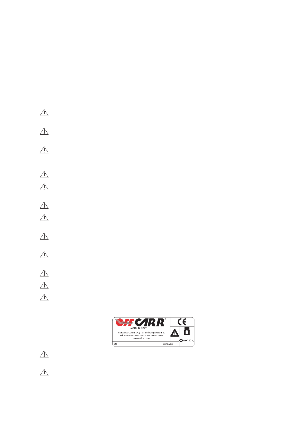
The registraon of the wheelchair and the address of the manufacturer can be found on a small scker
located underneath the wheelchair’s lower frame. This scker must never be removed, at risk of invalidang
the product's guarantee.
The indicated life span of the wheelchair is 2 years under normal usage condions, subject to it always
being used by the same person and undergoing regular maintenance.
The brake is for parking purposes only and must not be used as a service brake to slow the wheelchair
when in moon.