Decathlon TW500 User manual

TW500
RACKET SPORTS WHEELCHAIR
FAUTEUIL ROULANT DE SPORTS DE RAQUETTE
SILLA DE RUEDAS DE DEPORTES DE RAQUETA
ROLLSTUHL FÜR SCHLÄGERSPORTARTEN
CARROZZINA PER SPORT DI RACCHETTA
CADEIRA DE RODAS PARA DESPORTOS COM RAQUETE
WÓZEK INWALIDZKI DO SPORTÓW RAKIETOWYCH
SPORTOVE S REKETOM KOLICA
ŠPORTE Z LOPARJI INVALIDSKI VOZIČEK
INSTRUCTION FOR USE - MODE D’EMPLOI - MODO DE EMPLEO - GEBRAUCHSANWEISUNG - GUIDA
PER L’UTENTE - MODO DE UTILIZAÇÃO - INSTRUKCJA OBSŁUGI - UPUTE ZA UPORABU - NAVODILA ZA
UPORABO

ENGLISH 2
FANÇAIS 22
ESPAÑOL 42
DEUTSCH 62
ITALIANO 83
PORTUGUÊS 103
POLSKIE 123
HRVATSKI 143
SLOVENŠČINA 163
1

Please read this manual carefully before adjusng or using this product.
If necessary, contact Decathlon or the manufacturing company at the address provided below.
Should you suffer from visual impairment, please download the manual in PDF format from our
website:
www.decathlon.com
Wheelchair designed and manufactured by:
OFF CARR s.r.l.
Via dell’Argianato II, 29
35010 Villa del Conte (Padova) Italy
Tel. +39 049 9325733 Fax +39 049 9325734
E-mail: offcarr@offcarr.com hp://www.offcarr.com
If necessary, and for any further details regarding the safety of the wheelchair, repairs and ordinary or
extraordinary maintenance, please contact:
DECATHLON
4 BOULEVARD DE MONS - BP 299
59650 VILLENEUVE D’ASCQ CEDEX - FRANCE
hps://www.decathlon.com
All rights reserved
2

1. Introducon 4
TW500 Descripon 4
TW500 Features 5
2. Warning 5
3. Supplied base configuraon 6
First use 6
Base configuraon 7
4. Adjustments 7
Adjusng the seat depth 7
Adjusng imbalances (COG) 10
Adjusng the height of the fore-a seat in relaon to the ground 10
Adjusng the fore-a seat height in relaon to the ground 1 2
Adjusng the height of the backrest 1 2
Adjusng the height of the clothing protecon rims 1 3
Adjusng the backrest incline 1 3
Adjusng the tautness of the backrest canvas 1 4
Adjusng the posion of the footrest 1 4
Adjusng the an-lt wheel 1 5
Adjusng the thigh aachment strap 1 5
Assembling the pelvic strap 1 6
Adjusng and replacing the hand grip 1 6
5. Tips and recommendaons for use 1 7
6. Maintenance, inspecons and checks 1 7
Replacing the tyre and air chamber 1 8
Replacing the castors and bearings 1 8
Checking the quick removal devices 1 9
7. Cleaning and disinfecon instrucons 20
8. Packaging, transport and delivery 20
9. Material idenficaon 21
3

1. Introducon
TW500 is a wheelchair designed to meet the needs of adult and teen tennis and racket sport players. Made
with a lightweight aluminium alloy, it offers a wide range of adjustments, meaning it can be configured in line
with the athletes’ needs and the requirements of their various pathologies. Plus, it means it can accompany
them as they develop and progress in their sport, from leisure to compeons. The wheelchair complies with
the following standards:
ISO 7176-8 (test model 120 kg)
ISO 7176-16
You must NOT use wheelchairs and their elements incorrectly or for uses other than those indicated
in this manual.
1.1 TW500 Descripon
The TW500 tennis wheelchair is characterised by its frame which divides into two secons: A lower frame or
base, and an upper frame or seat. The base determines the geometry of the wheelchair’s footprint, the seat
and the aachment of the drive wheels, the small direcng front wheels and the rear an-p wheels and
includes the footrest and its controls.
1. Backrest
2. Seat
3. Side guards
4. Hand grip
5. Footrest
6. Front guard
7. An-p wheels
8. Front wheel sockets
RW Rear wheels
FC Front wheels
1.2 TW500 Features
● Aluminium alloy frame.
● D 72 mm height and depth-adjustable an-p wheel.
● Predefined camber: 20°
● Drive wheels: 25”
● High pressure re with 25”x1 (25-559 mm) diameter
● Aluminium push ring
● Rotang front wheels 72 mm diameter, 23.5 mm width
● Selectable seat width: 340, 360, 380, 400 mm
● Seat depth: 340, 360, 380, 400, 420 mm adjustable
● Axle/backrest distance: from 60 to 210 mm adjustable in 10 mm steps
● Backrest height: 250, 270, 290, 310, 330, 350, 370, 390 mm adjustable
● Backrest incline (in relaon to ground): +5° -5°
● Seat front height in relaon to ground: adjustable from 400 to 540 mm
● Seat rear height in relaon to ground: adjustable from 340 to 530 mm in 10 mm increments
● Seat inclinaon:min -8°, max 34°
● Leg incline in relaon to seat: min 50°, max 130°
● Footrest Height, Incline and Distance in relaon to the axle: adjustable
4

● Foot strap: standard
● Polyurethane cushion 75 sh., H 50 mm (prof. Std. 400 mm) not an-sores.
● Thigh strap H 80 mm (size M 560+ 1100 mm, size L 680+ 1200 mm)
● Shin strap: H 50 mm
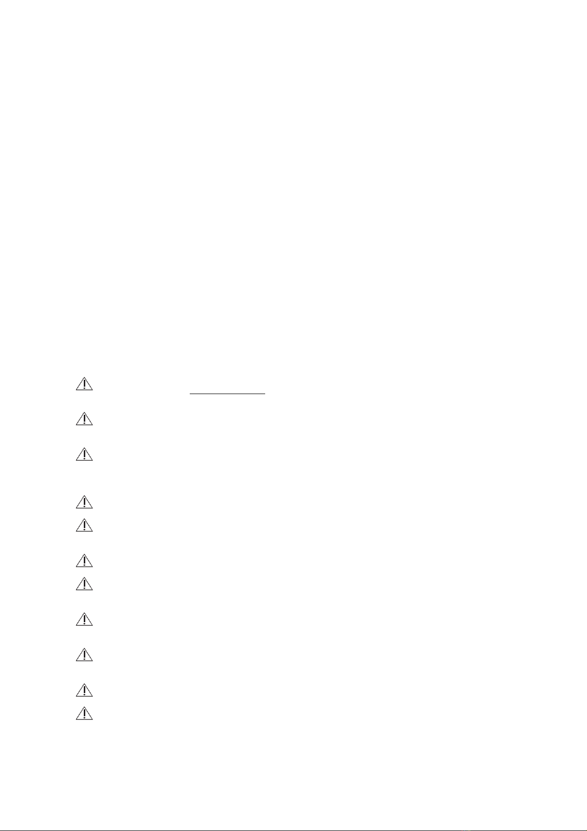
● Frame protecon: Padding on front and on rear bar
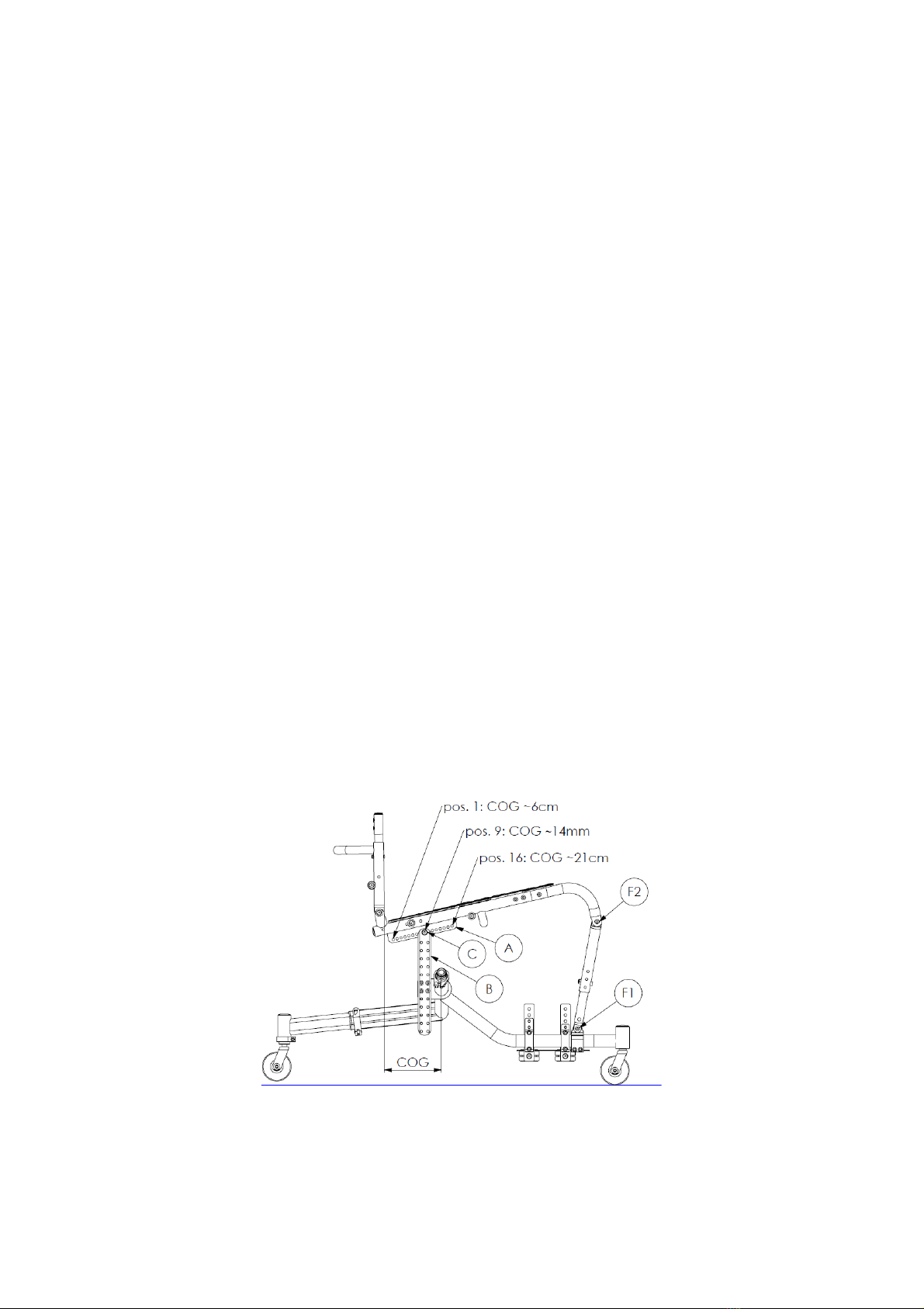
● Volume:
o Total width: min 790 mm, max 930 mm [700 mm ]**
o Total length: min 840 mm, max 890 mm [1200 mm]**
o Total height: min 570 mm, max 960 mm [1200 mm]**
o PIVOT width: min 1580 mm, max 1860 mm [1300 mm] **
o Hand rim: min 790 mm, max 930 mm [1000 mm] **
** Note: Some volume measurements may be greater than the measurements set out in the
EN ISO 12183 regulaon [xxx mm]. In some cases, it may be difficult or impossible to use
emergency exits provided.
● Weight: min 15 kg, max 15.9 kg
● Maximum load: 120 kg
2. Warning
The user is reminded that they should carry out a self-assessment of the crical points associated with their
specific pathology, and with their parcular postural requirements, before proceeding with any adjustments or
use of the wheelchair. OFFCARR does not accept any responsibility for any damages caused by incorrect
seang in the wheelchair, or by features of sing in the wheelchair which are incompable with the user's
pathology.
The cushion provided IS NOT ANTI-SORE , it is made with expanded polyurethane with a density of 75
shore with a Nylon fabric cover.
Avoid contact of the wheelchair with water. Undesirable rust may occur on some metal parts and/or loss
of the safety features of the materials concerned.
The wheelchair must only be used for the sport it has been designed for, or for compable disciplines,
and not for transporng objects in general, and it must not be used in other contexts. This could be dangerous
insofar as some of the usual safety elements for the wheelchair in moon are absent (e.g. Parking brakes, etc.).
Allergies caused by contact with parts of the wheelchair should be reported.
Keep the wheelchair away from heat sources in order to avoid any of the components seng alight. The
coverings meet the criteria for the standard ISO 7176 16:2012.
Do not put your fingers into the spikes when the wheelchair is in moon.
Inflate the tyres to a pressure within the range indicated inside the tyre. If transporng by plane, it is
suggested that you deflate the tyres to avoid excess pressure.
Always check that the quick wheel removal devices are working properly, especially if you tend to take
them off and put them back on frequently.
The wheelchair must be regularly maintained, so that it is kept in good, working condion but especially
so that the safety condions are upheld.
Inefficient maintenance and the improper use of the device may cause damages and injury to users.
Alteraons may invalidate the minimum safety condions.
5

The registraon of the wheelchair and the address of the manufacturer can be found on a small scker
located underneath the wheelchair’s lower frame. This scker must never be removed, at risk of invalidang
the product's guarantee.
The indicated life span of the wheelchair is 2 years under normal usage condions, subject to it always
being used by the same person and undergoing regular maintenance.
3. Supplied base configuraon
The TW500 tennis and racket sports wheelchair comes ready-to-use with a standard configuraon of the
variable parameters.
3.1 First use
The wheelchair is shipped with the rear wheels removed. To posion the front wheels, hold down the axle
buon to add the wheel onto the axle and then push it into the special guide of the wheelchair’s frame, then
release the buon. It is advised that you check the pressure of the wheels before use, ensuring they're at 7.6
BAR. The inflaon pressure is indicated on the sides of the tyre covers. Nevertheless, it is recommended to
always check that the drive wheels are inserted correctly before using the wheelchair, namely by checking
that the buon has been released, and by trying to pull the wheel outwards without pressing on the buon.
3.2 Base configuraon
The TW500 wheelchair comes with the following adjustment:
Seat width
L
as requested
Drive wheels
W
25”
Seat depth
D
400 mm
Backrest height
HS
290 mm
Backrest incline
IS
91°
Front height of the seat in relaon to the ground
FH
500 mm
Rear height of the seat in relaon to the ground
RH
400 mm
Centre of gravity
COG
140 mm
Distance of the footrest from the ground
FD
410 mm
Cushion H 50mm
L x 400 mm
Thigh strap H 80mm
L x 3.5
6

4. Adjustments
4.1 Adjusng the seat depth
When selecng the appropriate seat depth, it is recommended that you leave a margin of at least 30 or 40 mm
between the front rim of the seat and the back of the knees or the calf. During trial phases, and especially
during game play, it is essenal that you use a cushion; It is reminded that the cushion provided with the
wheelchair is not an-sore and its depth is 400 mm. If there’s no sign or reporng of any parcular sensivity
in the skin, you can use the cushion provided. Otherwise, it’s preferable to use a cushion adapted to the user’s
specific needs, such as the cushion they use daily, if it's compable with the dimensions of the sport
wheelchair. Should you have any doubts, please consult your doctor or therapist.
4.1.1 Seat cover depth adjustment
The seat is composed of three separate secons, each with a strap to adjust the tautness.
Follow the instrucons below to adjust the depth of the seat:
● Remove the “ALS” screws which aach the front secon of the “AL” seat to the main frame.
● Assess whether, with the new configuraon, you also need to remove the central “AK” secon, to
7

avoid overlaps. In this case, remove the “AKS” screws
● Set the front posion in the new posion, following the diagram provided, and reinsert the “ALS”
aachment screws.
● Put back the central secon, if you’ve removed it, sll following the diagram provided, and reinsert
the “AKS” screws.
● If necessary, adjust the ghtness of the wrist straps and the overlap of the extra fabric pieces on the
central secon.
4.1.2 Standard configuraon of the depth of the seat frame
The depth of the standard frame is 420 mm. This configuraon allows you to adjust the seat, or base, to fit the
cushion between 340 and 420 mm. It should be emphasised that the curve of the frame is located towards the
rim of the seat, when it has a depth between 380 and 420 mm, and is further away or longer when the depth
of the seat is between 340 and 380 mm. The images below show the standard configuraon.
You should note the posion of the “L” telescopic joints with the “xx” split located towards the boom, and the
inseron of the “K“ extension between the “J” frame and the “L” joints. The “M” screws aach the telescopic
joints tot eh frame and it's important that they’re properly ghtened, so that they contribute to the stability of
the frame. The “N“ screws are solely for aaching the extensions, and for prevenng them from rotang so
that their upper secon is free.
4.1.3 Reducing the depth of the seat frame
This opon can only be used when the depth of the seat is adjusted to between 340 and 380 mm.
LONG FRAME RECONFIGURATION
SHORT CONFIGURATION SHORT FRAME
8

Please note that, in relaon to the standard configuraon illustraon in paragraph 4.1.2, in this configuraon
with a reduced depth, the “K” 40 mm extensions are eliminated and the telescopic “L” insert is rotated 180° to
allow for the seat to be properly aached. Follow the instrucons below to reduce the depth of the frame by
eliminang these extensions:
● Firstly, you need to remove the “AL” front secon and the “AK” central secon of the seat by removing
the “ALS” and “AKS” screws as indicated in paragraph 4.1.1.
● Unscrew, but don't remove, the “F1” screws which lock the rotaons of the front mount in relaon to
the base frame (see Fig. Par. 4.2).
● Remove the “F2” screws which lock the rotaon of the telescopic joints in relaon to the front mounts
(take care to also remove the threaded pivot inserted between the rotang joints).
● Remove the “N” screws which aach the K extensions to the joints.
● Remove the “M” screws which aach the telescopic “L” joints to the seat.
● Slide the telescopic “L” joints out of the seat and remove the “K” 40 mm extensions.
● Turn the telescopic “L” joints by 180° by turning the “XX” slot upwards at the start of the rod.
● Completely reinsert the telescopic joints over the seat tube “J”.
● Put the “M” screws back in and ghten them properly.
● Assemble the seat, as indicated in paragraph 4.1.1.
4.2 Adjusng imbalances (COG)
The imbalance or centre of gravity corresponds to the horizontal distance from the backrest to the axle of the
drive wheels . This is a key parameter for distribung the load across the rear drive wheels and the front wheels
of the wheelchair, significantly influencing the agility and handling of the wheelchair. The imbalance is set 140
mm in advance, but it can be calibrated to another seng in approximate 10 mm increments:
● Remove the padded protecon from the front of the frame.
● Unscrew, but don't remove, the “F1” screws which aach the front mounts to the base of the frame.
● Unscrew, but don’t remove, the “F2” screws to release the rotaon between the front mounts of the
seat.
● Unscrew and remove the “C” screws which aach the seat to the rear support bars.
● Move the seat forwards or backwards to find the desired COG.
● Put back and securely aach the “C” screw in the new posion.
● If no other changes are required for the configuraon, securely aach the “F1” and “F2” screws which
were previously unscrewed.
9

4.3 Adjusng the height of the fore-a seat in relaon to the
ground
The height of the fore-a seat in relaon to the ground is set at 500mm. The configuraon provided can be
adjusted between 440 and 540 mm. The chair also comes with a kit to accommodate front heights of 420 and
400 mm. To adjust the post posion between 440 and 540 mm, follow the instrucons below:
● Remove the padded protecon from the front of the frame.
● Unscrew, but don't remove, the “F1” screws which aach the front mounts to the base of the frame.
● Unscrew, but don’t remove, the “F2” screws to release the rotaon of the front mounts in relaon to
the seat.
● Unscrew and remove the “G” screws which aach the front telescopic secons of the frame.
● Select the desired seat height in relaon to the ground, measured between the edge of the seat and
the ground (FH).
● Put back and securely aach the “G” screws in the new posion.
● If no other changes are required for the seat configuraon, properly aach the “F1” and “F2” screws
which were previously unscrewed.
10

To adjust the fore-a seat posion of the wheelchair to 420 or 400 mm, use the hardware provided and follow
the instrucons below:
● Remove the front padded frame protectors.
● Loosen, but do not remove, the "M" screws that secure the frame curve to the seat
● Unscrew, but don’t remove, the “F2” screws to release the rotaon between the front mounts of the
seat.
● Remove the “F1” screws which aach the "H" interior mounts to the base of the frame.
● Remove the "H" mounts, the "F1" screws, the "D1" spacers and the "G" screws.
● Insert the supplied "A1" rods with the inside of the "F" exterior mounts,
● Aach the "A1" rods to the "F" tube using the "F4" screw, selecng the hole which corresponds to the
height desired.
● Aach the exterior mounts to the "M1" bracket using the "F3" screw, "D3" disc washers and "D2"
brass sleeves as shown in the illustraon.
If no further modificaon of the seat insert is required, ghten the previously loosened "F2" and "M" screws
properly.
4.4 Adjusng the fore-a seat height in relaon to the ground
The height of the fore-a seat in relaon to the ground can be adjusted to between 340 and 530 mm by
following the instrucons below:
● Unscrew, without removing, the “F1”, “C” and “F2” screws to release any locked rotaons and
movement of the seat mount.
● Unscrew and remove the “E” screws which aach the rear support bars.
● Select the desired height of the seat in relaon to the ground, measured from the end of the seat to
the ground “RH”.
● Put back the “E” screws in the new posion and securely ghten them.
● If no other changes are required for the seat configuraon, securely aach the “F1” and “F2” screws
which were previously unscrewed.
4.5 Adjusng the height of the backrest
By default, the height of the backrest is set at 290 mm. Nevertheless, it can be adjusted to between 250 and
390 mm by following the indicaons below:
● Li and remove the canvas of the backrest, which is aached by the velcro strips on the support
straps.
● Unscrew the (F) screws which aach the adjustment extensions for the backrest height.
● Select the new height for the backrest.
● Put back the (F) screws into the new posion and securely ghten them.
● If you need to add one or more velcro support straps for the external padding.
● Re-install the backrest canvas, taking care to fold any overhang under the cushion.
11

NOTE: The wheelchair comes with two sets of backrest extensions. The short set covers a height
adjustment to between 250 and 310 mm. The extended set covers a height adjustment to between 330
and 390 mm. The support straps provided cover the whole adjustment range, just like the padded
canvas cover.
4.6 Adjusng the height of the clothing protecon rims
It’s recommended that you define the posioning of the protecon height in relaon to the wheels before
connuing with adjusng the incline of the backrest, in order to eliminate any clashes and needing to redo any
adjustments.
● Removing the drive wheels.
● Unscrew and remove the “P”, “Q”, “V” and “Y” screws which aach the protecon to the frame and
which set the adjustment of the backrest incline.
● Determine whether you need to remove the incline adjustment. You need to remove it if the “T”
screw has also been passed through the protecon. In this case, also remove the “T” screw, taking
care to note the sequence of the washers for when you put it back together.
● Select the preferred posion by using the “P” and “Q” slots nearest to the relevant holes.
● Reinsert all the “P”, “Q”, “V” and “Y” screws that were previously removed and securely ghten them.
If the supporng “T” screw has been removed, it must be reinserted first.
4.7 Adjusng the backrest incline
Before adjusng the backrest incline, you should make sure that the clothing protecon rim is posioned at
the desired height. If necessary, first adjust the height of the rim, following the instrucons provided in
paragraph 4.7 and then connue as follows with adjusng the incline of the backrest. Operaons should
always be carried out symmetrically on the right and le sides, in order to be able to make the required
rotaons. It is recommended that, when the screws are removed, you take note of the sequence of the
washers and thicknesses used, so that you can put them back in the right order.
● Unscrew, without removing, the “P” and “Q” screws to release any locked rotaons and movements of
12

the clothing protecon rim.
● Unscrew, without removing, the “T” screws to release the rotaon of the backrest.
● Unscrew and remove the “V” screw which aaches the incline adjustment onto the seat frame.
● Select the new incline of the backrest.
● Find the hole from those idenfied by “V1, V2, V3, V4” which match up with one of the holes on the
frame, idenfied by “U1, U2, U3, U4”.
● Once you’ve found the corresponding hole, insert the “V” screw and properly secure it to set the
posion of the adjustment.
● Connue by ghtening the “F”, “P” and “Q” screws which were previously unscrewed.
4.8 Adjusng the tautness of the backrest canvas
● Li the rear secon of the canvas.
● Loosen the straps.
● With the athlete in playing posion, pull taut the straps as much as necessary, starng with the top
strap.
● Fold the backrest canvas back again.
● Try some game movements and repeat the operaon if the posion isn't quite right.
4.9 Adjusng the posion of the footrest
The height, depth and incline of the footrest can be adjusted.
13

Footplate height is adjusted by varying the posions of the "F5" screws in relaon to the support plates, as
follows:
● Unscrew and remove the 6 "F5" screws between the plates and blocks "EE" and "FF".
● Align the holes to obtain the desired posion.
● Re-insert and properly ghten the "F5" screws.
The angle can be varied by fing the "F5" screws at different heights to the front and rear plates.Depth is
adjusted by varying the posion of the "EE" and "FF" blocks in relaon to the frame or the plaorm in relaon
to the "CC" blocks.Changing the posion of blocks "EE" and "FF" is easier and allows for more posion
possibilies. To change the posion of the "EE" and "FF" blocks:
● Loosen the "F6" screws without removing them
● Choose the desired posion
● Tighten the "F6" screws firmly
To change the posion of the footplate in relaon to the "CC" blocks:
● Unscrew and remove the “F7” screws.
● Align the holes to obtain the desired plaorm posion.
● Re-insert and properly ghten the "F7" screws.
4.10 Adjusng the an-lt wheel
To adjust the depth of the wheel:
● Unlock the "K" collar by pulling the lever
● Increase or decrease the depth of the wheel to suit your requirements
● Tighten the "K" collar
● If the collar is too ght, turn the handle counterclockwise several mes, if it is too loose, turn it
clockwise unl you get the right tension
To adjust the height of the wheel:
● Loosen but do not remove the "AH" screw which determines the an-lt wheel's height relave to the
ground.
● Raise or lower the wheel as desired.
● Tighten the "AH" screw firmly.
4.11 Adjusng the thigh aachment strap
Preparaon
The thigh aachment strap is made up of:
● A padded strap (A) with 2 buckles (B),
● A mobile buckle (C),
● An aachment strap (D).
14

● Prepare the strap by bringing together both secons “A” and “D” to obtain the desired length
“consider the reference length to be W x 3.25, W being the width of the wheelchair)
● Insert the strap between the frame and the rims, passing it under the seat.
Adjustments
The adjustment of the thigh aachment strap must be made with the athlete sing in the wheelchair.
● Posion strap (A), making sure that the padding is on top of the thighs.
● Insert the aachment strap (D) into one of the two upper buckles (B), taking into account the most
comfortable posion for the user.
● If the length isn't suitable, it can be adjusted by adapng the connecon of the two straps with velcro
“A” and “D” which can be found underneath the seat.
4.12 Assembling the pelvic strap
The rim of the TW500 is composed of two elements, including one with slots for potenally aaching a pelvic
belt.
4.13 Adjusng and replacing the hand grip
The hand grip can be assembled into three different posions to create a larger or smaller distance “A” from
the wheel hoop. To access the hand grip aachment screws, you need to remove the cover, the air chamber
[paragraph 6.1] and the protecon flap (G).
15

To remove the hand grip from the wheel, you need to completely remove all six aachment screws (F). Once
the hand grip has been removed, you can reaach it by selecng one of the three possible posions on the
aachment tabs (see illustraon).
Once the hand grip has been re-aached, proceed with the reposioning of the flap (G), making sure to match
up the hole for the valve with the corresponding hole in the hoop. We recommend centering the flap (G)) over
the hoop to ensure maximum protecon for the air chamber.
5. T ips and recommendaons for use
The greater the imbalance, namely the wheelbase between the wheel hub and the backrest axle, the easier the
wheelchair is to handle and the beer its response to changes in direcon. The height of the an-p castors in
relaon to the ground should be adapted to the athlete’s game habits. It is recommended that you avoid the
possibility of connual contact with the an-p castors, insofar as they slow down the wheelchair's movement
and interfere with its direcon. If needed, the padding can be washed at low temperatures. Nevertheless,
avoid immersing the other, mechanical parts of the wheelchair in water. Keep the wheel castors clean,
parcularly the front and an-p castors, and the rotaon axles of their forks, so that the wheelchair always
funcons as efficiently and as effecvely as possible.
6. Maintenance, inspecons and checks
ATTENTION!
● Always check that the quick removal device for the drive wheels is properly locked.
● The wheelchair should be regularly checked to ensure it remains efficient and safe.
● Insufficient maintenance and improper use of the wheelchair may cause damages and injury to
people or property.
● There is no obvious risk of personal injury during use of the wheelchair insofar as it has been
designed to reduce the risks of accidents in use or in preparaon for use. Nevertheless, as it is a
specific product for use in certain sports, it may become hazardous if used in other contexts.
● Should you need to replace any elements, it is recommended that you only use original spare
parts or spare parts that have been authorised by the manufacturer.
● Should you encounter any difficules in finding spare parts on the market, please contact
DECATHLON.
16

Each week :
● Check the tyre pressures. On the side of each wheel cover, you’ll find the recommended tyre pressure.
A deflated tyre compromises the efficiency of the brakes and the fluidity of the wheelchair’s
movements.
● Check the efficiency of the quick removal devices [paragraph 6.3], clean them, and if necessary, oil the
axles and dowels with a lile grease to ensure that the wheels can be simply removed and replaced.
Each quarter:
● Check for wear on the front wheels, which may alter the rear seat of the wheelchair if significantly
worn. In this case, proceed with replacing the wheels [par. 6.2].
● Check the bearings on the front and rear wheels, and on the fork rotaon. In this case, replace the
bearings [par. 6.2].
● Grease the mobile parts, such as the quick removal axles of the wheels and the guides for the wheels.
We recommend using silicon oil as a grease, as it's effecve and non-staining.
6.1 Replacing the tyre and air chamber
Disassembling the tyre and air chamber
● Deflate the tyre
● Install a special lever between the circle and the shoulder of the tyre, so that when the lever is lted,
the side of the wheel comes out (fig. 1 and 2)
● Install another lever 100 mm from the previous point and repeat the operaon (fig. 3)
● Slide the two levers around the whole circle to release the enre tyre.
● Remove the air chamber, starng with the side opposite the inflaon valve (fig. 4)
● Once the air chamber has been removed, you can easily remove the tyre to replace either or both of
them.
Assembling the air chamber and tyre
● Remove the air chamber (deflated) in the tyre (fig. 5).
● Insert the air chamber inflaon valve into the whole intended for this purpose, located on the circle.
● Around the whole circle, install the tyre, taking note of the direcon of the tyre, which indicates
whether it's the right or le drive wheel.
● Install the opposite shoulder over the tyre, starng from the point where the valve is, moving round in
both direcons.
● Insert the final part of the shoulder with the help of the levers intended for this, reversing the
instrucons shown in Fig. 3, Fig. 2, and Fig. 1.
● Inflate the tyre to the pressure indicated on its side.
FIG. 1 FIG. 2 FIG. 3 FIG. 4 FIG. 5
6.2 Replacing the castors and bearings
Wheel replacement (Fig. 6)
● Unscrew and remove the “4” screws.
● Remove axle “3” from its seat.
● You can freely remove the wheel.
17

FIG. 6 FIG. 7
Replacing the wheel castors (Fig. 7)
● The front wheel castors (608 zz) are mounted with just pressure. To remove them, you just need to
push them out from the inside.
● In the illustraon, you can see a strut “2” between the two bearings. When reassembling, you must
reinsert this strut to set the correct distance between the two bearings.
Replacing the bearings of the drive wheels (fig. 8)
● Disassembly
◦ The drive wheel bearings (6001/12,7 2RS) are mounted by applying pressure. To remove them,
you simply need to push them from the inside, using a pin dri and a hammer.
● Assembly
◦ Posion a new bearing on the inner side of the hub, taking care to insert it evenly (it must be
co-axial with the hub, otherwise it won't go in).
◦ Before posioning the two bearings, on the opposite side, you need to insert the quick removal
axle into the bearing which has already been inserted, so that the axle itself acts as a guide for the
two bearings. This way, you make sure that the hub and three bearings are co-axial.
FIG. 8
6.3 Checking the quick removal devices
The quick removal axles provided are checked and adjusted: Ø 12.7 mm x Usable L 130 mm. Nevertheless, we
recommend carrying out this check regularly during their use.
Check :
● Make sure that the “X” buon has been enrely released (fig. 10), once the wheel has been
assembled.
18

● Pull the wheel towards the outside of the wheelchair (fig. 11), and the wheel shouldn’t come out
without you pressing the buon.
FIG. 9 FIG. 10 FIG. 11
Adjustment :
If needed, you can adjust the axle to eliminate any potenal alteraons between the wheel and the frame, or
to complete the release of the buon when the wheel has been added.
● If, once the wheel has been fied into the frame, the axle buon isn't completely released, you need
to extend the usable length of the axle ”L” by parally unscrewing the “Z” nut.
● If, once the wheel has been fied into the frame, there’s interference between the frame and wheel,
you need to extend the usable length of the axle ”L” by parally unscrewing the “Z” nut.
Note: The “Z” nut has a 1 mm thread, and consequently, the one-turn screwing includes extending or
reducing it by 1 mm / If adjusng, it is recommended that you make successive adjustments of 1/4 turn
at a me.
7. Cleaning and disinfecon instrucons
ATTENTION! Use the appropriate eye/face protecon and gloves during cleaning and disinfecon
operaons.
If the wheelchair comes into contact with blood or other bodily fluids, it must first be cleaned and disinfected,
following the instrucons below.
Note: In most cases, it is more interesng and more efficient to remove the seat and backrest canvas before
cleaning and disinfecng..
Frame
● Was the wheelchair with a damp cloth, using warm water and neutral soap to remove dirt or stains.
● Wash the wheelchair again with a damp cloth to remove the detergent product.
● Wipe down the wheelchair
● Visually check that the wheelchair is clean
● disinfect the wheelchair with 70-90% alcohol.
● Make sure that the wheelchair is completely dry before proceeding.
Canvases
If the user is the same before and aer cleaning:
● Wash, rinse and disinfect the canvases, using the same procedure as used for the frame.
● Make sure that the canvases are completely dry before re-aaching them to the frame.
If the user changes aer cleaning:
19
Table of contents
Languages:
Other Decathlon Wheelchair manuals