Decatur DragonEye Compact User manual
DragonEye
Compact
User’s Manual
Rev 10/25/2012
Speed LIDAR


DragonEye
Compact
User’s Manual
Speed LIDAR

Table of Contents
Welcome to Decatur Electronics .......................................6
About This Manual ....................................................7
1 Safety Information ....................................................7
2 Receiving Inspection ..................................................9
3 Getting Started ......................................................10
3.1 Introduction.....................................................10
3.2 Diagrams, Controls and Displays. . . . . . . . . . . . . . . . . . . . . . . . . . . . . . . . . . 10
3.3 Display Descriptions .............................................11
3.3.1 Side Panel Display (LIDAR in Speed Mode) . . . . . . . . . . . . . . . . . . . . . . 11
3.3.2 Head-Up Display (LIDAR in Speed Mode) . . . . . . . . . . . . . . . . . . . . . . . 11
4 Controls and Indicators...............................................12
4.1 Laser Fire Trigger.................................................12
4.2 Keypad Controls .................................................12
4.2.1 Mode Control..................................................13
4.2.2 HUD Brightness Control........................................13
4.2.3 Side Panel Display Backlight. . . . . . . . . . . . . . . . . . . . . . . . . . . . . . . . . . . . 13
4.2.4 Volume Control................................................14
4.2.5 Menu/Exit Menu...............................................14
4.2.6 Up and Down Arrows ..........................................14
4.2.7 Enter Button...................................................14
4.3 Battery Voltage Indications.......................................14
4.4 Jam / ECM Attempt Indication. . . . . . . . . . . . . . . . . . . . . . . . . . . . . . . . . . . . 15
5 Basic Operation ......................................................16
5.1 Battery Installation...............................................16
5.2 Powering On.....................................................16
5.3 Selecting Speed Mode ...........................................17
5.4 Using the HUD Sighting System . . . . . . . . . . . . . . . . . . . . . . . . . . . . . . . . . . 17
5.5 Roadside Setup..................................................18
5.6 Measuring Vehicle Speeds........................................18
5.7 Speed Display Lock ..............................................19
5.8 Speed Display Lock Retention . . . . . . . . . . . . . . . . . . . . . . . . . . . . . . . . . . . . 19
5.9 Range Mode.....................................................20
6 Advanced Controls and Modes .......................................21
6.1 Self Test Initiation................................................21

6.2 Weather Modes..................................................21
6.2.1 Normal Weather Mode.........................................21
6.2.2 Poor Weather Mode............................................21
6.3 Minimum and Maximum Ranges (Range Window) . . . . . . . . . . . . . . . . 22
6.4 Direction Filter...................................................23
6.5 Dierential Distance Test.........................................23
6.5.1 Dierential Distance: LIDAR in English Units (MPH). . . . . . . . . . . . . . 24
6.5.2 Dierential Distance: LIDAR in Metric Units (KPH) . . . . . . . . . . . . . . . 25
6.6 Timed Distance Mode............................................25
6.7 Load Defaults....................................................27
6.8 ECCM Control....................................................27
6.9 Input / Output Port ..............................................28
7 Recommended System Checks .......................................28
7.1 Self Test .........................................................28
7.2 Alignment Test...................................................28
7.3 Fixed Target Distance ............................................29
7.4 Certication .....................................................29
8 Care, Cleaning and Storage...........................................29
8.1 Guidelines......................................................29
8.2 General Handling . . . . . . . . . . . . . . . . . . . . . . . . . . . . . . . . . . . . . . . . . . . . . . . 30
9 Specications........................................................31
9.1 Distance Parameters .............................................31
9.2 Electrical ........................................................31
9.3 Environment.....................................................31
9.4 Mechanical ......................................................31
9.5 Optics ...........................................................31
9.6 Speed Range Parameters.........................................32
10 Cosine Eect.........................................................33
11 Troubleshooting and Service Guide. . . . . . . . . . . . . . . . . . . . . . . . . . . . . . . . . . . 34
12 Warranty & Service ...................................................35
13 How to Order Additional Products . . . . . . . . . . . . . . . . . . . . . . . . . . . . . . . . . . . . 37
User Notes...........................................................38

DragonEye Compact User’s Manual
6
Welcome to Decatur Electronics, Inc.
Thank you for choosing the DragonEye Compact— A highly
advanced speed LIDAR that will reward your department with years
of dependable service. We urge you to study this manual before
using the DragonEye Compact so you can maximize the benets of
this sophisticated LIDAR device. We believe you will be pleasantly
surprised by the features and advantages.
If you are as pleased with its performance as we think you will be, ask
your Decatur sales representative about other products including the
Decatur Genesis™ line of radars, the Onsite™ line of speed trailers,
dollies, and pole signs and the Responder™ line of in-car video
systems.
—The Management and Sta at Decatur Electronics,
The Nation’s Oldest Radar Company

DragonEye Compact User’s Manual
7
About This Manual
This manual contains valuable information to help you set up, use
and maintain your LIDAR, so you can optimize its life and keep it at
peak performance. Please take a moment to read through it, and
keep it handy for future reference.
Note the following symbols in this manual:
Indicates a warning message about safety
precautions. Please read it carefully.
Indicates a helpful tip, notice or precaution to note.
1. Safety Information
All service needs should be referred back to the manufacturer.
GENERAL WARNINGS
• When replacing batteries in the DragonEye Compact
you should replace both batteries with new ones even
if you suspect that only one cell is defective.
• Use rechargeable Nickel-Metal-Hydride or high quality
Alkaline AA-cell batteries only.
• Opening the DragonEye Compact (other than battery
replacement) automatically voids any warranty still in
eect. There are no user serviceable parts inside.

DragonEye Compact User’s Manual
8
NOTICES AND PRECAUTIONS
The DragonEye Compact Speed LIDAR is a Class 1 Laser
product in accordance with U.S. 21CFR parts 1040.10
and 1040.11, which is safe for use in all intended
operation modes. However, standard precautions
should always be taken with laser products:
• Avoid staring into the output aperture of the device.
• Avoid directing the LIDAR at other individuals for
prolonged periods.
• Do not direct the output of the LIDAR at anyone using
optical instruments such as binoculars as this will
increase the risk of eye hazard.
• Use of controls or adjustments or performance of
procedures other than those specied herein may
result in hazardous radiation exposure.
• Do not point the device at the sun! Do not aim the
LIDAR directly at the sun as this could damage the
internal components.
CAUTIONS
• Do not expose the DragonEye Compact to excessive
moisture. Never submerge the device.
• Do not drop the DragonEye Compact on hard surfaces
since damage could occur. Units damaged by dropping
or abuse are not covered for warranty repair.
Violation of these guidelines may void the warranty.

DragonEye Compact User’s Manual
9
2. Receiving Inspection
• When you receive your unit, inspect all components for
freight damage that might have happened during shipping or
unloading.
• Notify the freight company immediately of any damage,
preferably while the driver is present. Record the damage on the
bill of lading and keep a record of the problems or damage. Take
pictures to document any damage.
• The package should include the following pictured items along
with this User’s Manual.
DragonEye Compact speed LIDAR Two "AA" Cell batteries
Soft Pack Carry Pouch
(Pouch style may vary)
If your DragonEye Compact LIDAR was ordered with any special
accessories, please check for those items and for any packing lists
or special instructions that might be included with those additional
items.

DragonEye Compact User’s Manual
10
3. Getting Started
3.1 Introduction
The DragonEye Compact is a high performance electro-optical
LIDAR providing accurate speed and distance measurements custom
designed for the law enforcement community. The LIDAR provides
pinpoint target identication via its clear heads-up display targeting
system and fast target acquisition using sophisticated, robust data
processing algorithms. The DragonEye Compact was designed for
compact, light-weight operation and long battery life. It provides
numerous useful settings and features including advanced ECCM
(Electronic Counter Counter Measures), inclement weather modes
and a USB interface for easy data interface and upgrades.
3.2 Diagrams, Controls and Displays
Use the diagrams and descriptions in this section to quickly
familiarize yourself with the DragonEye Compact LIDAR controls
and features. The following diagram shows the location of the key
external features of the device.
Figure 3.2
DragonEye Compact Layout
DragonEye Compact User’s Manual
11
3.3 Display Descriptions
The following gures show typical displays for both the side panel
and the HUD (Head-Up Display). Special menu displays and HUD
indicators will be covered in their respective selections of this
manual.
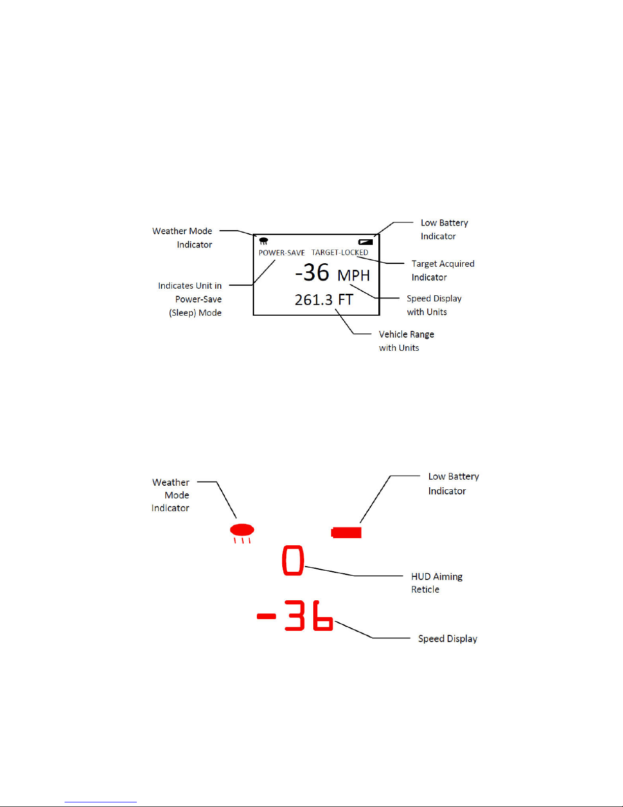
3.3.1 Side Panel Display (LIDAR in Speed Mode)
Figure 3.3.1
Side panel
3.3.2 Head-Up Display (LIDAR in Speed Mode)
Figure 3.3.2
Head-Up Display

DragonEye Compact User’s Manual
12
4. Controls and Indicators
The DragonEye Compact LIDAR has an ergonomically styled grip
with a top mounted laser re trigger and an easy to use side panel
keypad and display to select modes of operation and tailor settings
for particular conditions. The most frequently used functions have
been assigned a dedicated button to allow for extremely fast setup
and operation. Following is a description of the available controls for
your LIDAR system. Additional details are provided in the "Advanced
Controls and Modes" section.
4.1 Laser Fire Trigger
The Laser Fire Trigger is used to turn-on the DragonEye Compact
LIDAR when the unit is o and to initiate laser ring when the unit is
awake and ready. Simply press and release the trigger and the LIDAR
will wake up and be ready to re in a fraction of a second.
• If the unit has been o for an extended period or
new batteries have just been inserted, the device will
automatically run the Self Test routine.
4.2 Keypad Controls
All remaining controls are on the keypad located on the side of the
LIDAR, under the display. The following diagram shows the location
of the various buttons. Further descriptions of the button functions
are detailed in the following sections.
• Some control buttons are dual use and their secondary
function is indicated by the blue symbol located below
the primary symbol on the button. These secondary
functions are active only in "menu mode" after pressing
the menu button.

DragonEye Compact User’s Manual
13
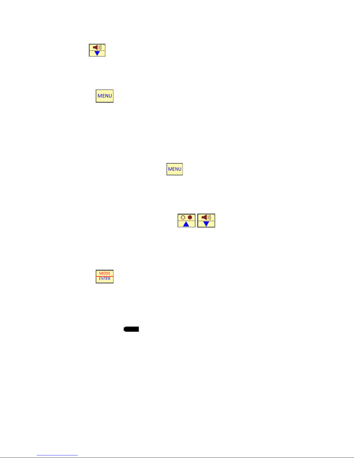
Figure 4.2
Keypad
4.2.1 Mode Control
Pressing toggles between Distance and Speed Measurement
Modes. In Speed Mode the side display will show "MPH" and "FT"
for Miles-Per-Hour and Feet; or "KPH" and "M" for Kilometers-Per-
Hour and Meters for devices programmed with SI units. In Range
Mode the display will simply show "FT" or "M" for range measured
in Feet or Meters.
• The LIDAR is factory set for English (mph) or SI (metric)
units and cannot be changed by the operator.
4.2.2 HUD Brightness Control
Use the button to toggle through the six HUD brightness
levels. (Note: Level 1 and Level 2 are typically used for night operation
only and will most likely not be visible in normal daylight conditions!)
4.2.3 Side Panel Display Backlight
The backlight for the side panel display is fully automated and
does not have an on/o control. The backlight will be illuminated
after each range or speed reading. It will be switched o during
targeting.
DragonEye Compact User’s Manual
14
4.2.4 Volume Control
The button toggles through the three volume levels for the
audible target tracking indicator. Use Level 1 to set audio OFF.
4.2.5 Menu/Exit Menu
The button is used to enter and exit the LIDAR's Menu
system. The Menu system allows the operator to adjust certain
parameters and features as well as enter the Time/Distance
mode. (See "Advanced Controls and Modes").
After the Menu button is pressed, the blue functions on the dual
use buttons become active. To exit the Menu system without
making changes, press the again.
The general description of blue function buttons are as follows:
4.2.6 Up and Down Arrows
While in the Menu system, the buttons are used to
navigate through the menu options, to highlight a desired item,
or to scroll through various values.
4.2.7 Enter Button
The button is used to select or activate a particular menu
item or value.
4.3 Battery Voltage Indications
When the LIDAR unit's batteries begin to run low on power, the
battery indicator will illuminate on both the side panel display
and HUD. (The side panel low battery symbol will be partially lled
in). The unit may continue to be used, and may last a considerable
amount of time particularly with low volume settings; however a
replacement set of batteries should be handy to avoid down time.

DragonEye Compact User’s Manual
15
When the batteries reach the end of their capacity, the side panel
will display:
Battery Voltage
Critical
Shutdown
in 5 Seconds
Figure 4.3
Side Panel showing batteries need replaced
The Unit will then automatically countdown to turn o.
• Signicant gains in battery life can be realized by
setting the audio and HUD brightness settings at the
lowest levels required for your environment.
4.4 Jam / ECM Attempt Indication
The DragonEye Compact LIDAR contains sophisticated counter
measures to defeat LIDAR "Jamming" devices available in the
consumer market place, while continuing to display accurate
speed readings. The system also indicates when a jammer or
other Electronic Counter Measure (ECM) is detected on the target
vehicle by displaying the phrase "Jam ECM" on the rear display and
ashing the " " symbol in the HUD. Note that extremely bright
surfaces on the target vehicle, such as high beam headlights or sun
reections can cause the jam indicators to turn on. If you experience
any diculty locking in a speed reading when "Jam" is indicated, try
moving the HUD aiming point to another location on the vehicle.
DragonEye Compact User’s Manual
16
5. Basic Operation
The following sections give an overview of the basic operation of
the DragonEye Compact LIDAR for normal speed measurement
applications. Be sure to review the "Recommended System Checks"
section to understand the suggested daily performance checks and
periodic certications. Additional details of special features and other
operation modes are in the "Advanced Controls and Modes" sections.
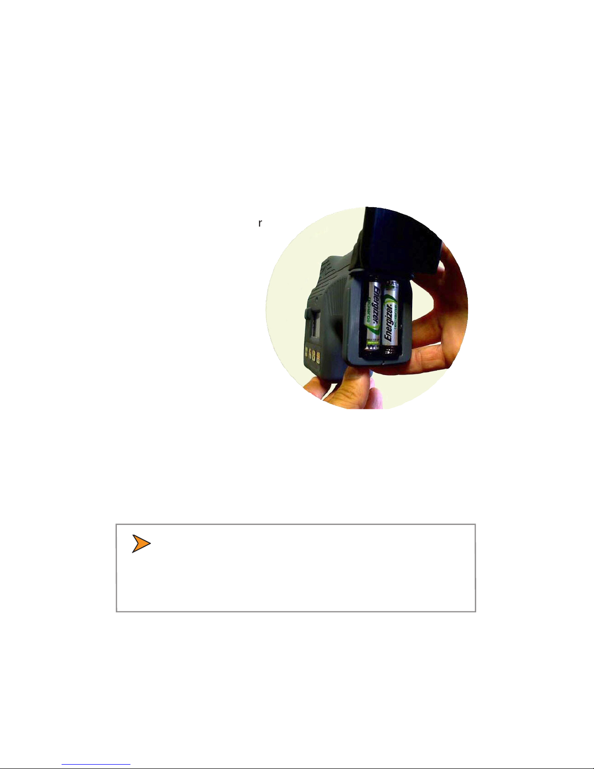
5.1 Battery Installation
Lift the rubber battery cover
from the lower corners and
remove the old batteries.
Figure 5.1
Battery Installation
Insert two "AA" cell
batteries, positive end
against the at contacts
and negative ends against
the spring contacts. Replace
the rubber batter cover and
press the snap in place.
The DragonEye Compact LIDAR is
designed to use quality alkaline
"AA" cells from brand name manufacturers.
The device also functions with rechargeable NiMH
"AA" cells commonly available at consumer stores.
• The LIDAR's rubber battery cover forms part of the
water resistant enclosure protecting the unit from rain
and moisture. Please be sure to change batteries in a
dry environment.
5.2 Powering On
When fresh batteries are installed, the unit will automatically power
up, run through Self Test and be ready for use.
DragonEye Compact User’s Manual
17
• If the LIDAR is inactive for approximately 30 seconds,
it will automatically transition into sleep mode to
conserve battery life. If this happens, simply click the
re trigger again to wake up the unit.
5.3 Selecting Speed Mode
The LIDAR will normally power up in "Speed" mode, unless it was
recently used in a dierent mode. If "Speed" mode is not displayed
on power up, simply press until the side panel displays:
MPH
FT
Figure 5.3
Side Panel indicating Speed Mode is active
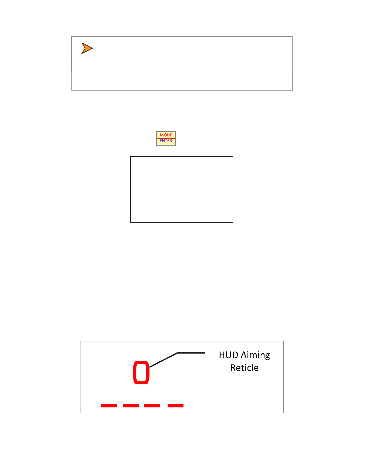
5.4 Using the HUD Sighting System
The Head-Up display provides a precision aiming reticle, speed
reading, and other status information. To nd the sighting reticle,
press and release the trigger to wake up the LIDAR and look directly
through the HUD letting your eyes focus on a target well in front of
the LIDAR unit. If you haven't used a HUD device before, it might take
a minute or two for your eyes to adjust the rst time.
Figure 5.4
HUD aiming

DragonEye Compact User’s Manual
18
• Make sure the LIDAR's brightness setting is on medium
or high if working in daylight.).
The LIDAR's laser beam is invisible, but will be contained within the
aiming reticle. This is your aim point for target vehicles.
5.5 Roadside Setup
When rst learning to use the DragonEye Compact LIDAR, it is best to
select a straight stretch of roadway with a line of sight of 500 ft
(150 m) or more.
Approaching or receding vehicles should be targeted such that your
line of sight through the HUD is as parallel as possible to the path of
the target vehicle. This will minimize the "cosine eect" as described
in Chapter 10 of this manual.
• The cosine eect applies to both RADAR and LIDAR
systems and always results in a slightly lower than
actual reading..
A good rule of thumb for approximately straight roadways is to
target a vehicle at a range which is at least ten times the operator's
perpendicular distance to the vehicle's lane of travel. For example,
if the operator is 30 feet (9 m) from the vehicle's lane of travel, the
vehicle should be targeted at 300 feet (90 m), or greater. This would
result in a measured speed reading which was approximately 0.5%
less than actual.
5.6 Measuring Vehicle Speeds
For approaching targets, aim the LIDAR's reticle at the front grill or
front license plate of the vehicle. Good targets for receding vehicles
are the license plate or tail lights. Use the boundaries of the reticle
pattern to ensure only the intended vehicle is being targeted.
Squeeze and hold the laser re trigger while maintaining your aim.

DragonEye Compact User’s Manual
19
You may hear an intermittent audible tone as the LIDAR searches
for a valid target signal. You will also see "----" displayed in the HUD
indicating the laser is ring and a reading is being acquired. Once
target vehicle data is identied, the LIDAR will product a continuous
lower frequency tone. When the data from the vehicle reaches an
acceptable accuracy level, audible tone will switch to a continuous,
higher frequency and the vehicle speed reading will be displayed in
the HUD and on the side panel.
• At typical distances the acquisition sequence can
happen very quickly and you may simply hear the high
frequency tone and see the speed display immediately.
A positive speed reading will be shown for an approaching vehicle,
while receding vehicles are indicated with a negative reading. (Both
the HUD and the back panel will show a "-" sign for receding vehicles.)
The DragonEye Compact LIDAR will continuously update the target's
speed reading at an approximate rate of 3 times-per-second as long
as the trigger is depressed and the data quality is acceptable. While
not required, it is recommended to track the vehicle for at least 1
second to establish robust condence in the speed reading.
5.7 Speed Display Lock
Once a desired speed reading is acquired, the operator can "lock" the
speed reading on the side panel display by simply releasing the laser
re rigger. If a speed reading is lost after tracking a vehicle, the last
speed reading will ash for approximately two seconds, giving the
operator an opportunity to lock in the vehicle's speed. (The ashing
speed reading will be immediately over written if the operator acquires a
new speed reading.)
5.8 Speed Display Lock Retention
Once a speed is locked into the side display, it will be retained there
for up to 20 minutes. If the laser re trigger is depressed within 30
seconds after the speed is locked, the display will clear and prepare
for a new reading. If no buttons are pressed for 30 seconds after the

DragonEye Compact User’s Manual
20
speed reading is locked, the unit will go into a sleep mode, turning
o the HUD and displaying "Power-Save" on the side panel along
with the locked reading. In the Power-Save state, a rst laser trigger
press and release will "wake" the LIDAR but retain the locked reading.
A second trigger press will then clear the reading. This feature is
intended to aid in preventing the operator from accidentally clearing
the locked reading.
5.9 Range Mode
The LIDAR system can be used to measure distances to a variety of
targets. To enter Range Mode, press the Mode Button until the
side panels displays:
FT
Figure 5.9
Side Panel indicating Range Mode active
Use the aiming reticle in the HUD to select your desired target.
Squeeze and hold the trigger down until a range reading is displayed
in the HUD and on the side panel display. The trigger may be
continuously held down as the unit is moved from target to target
for quickly checking multiple ranges. The last range reading in the
display is locked when the trigger is released. Range readings are
displayed in tenths of a foot on the side panel and in the HUD up to
999.9 feet (or 999.9 m). Above this, range readings are displayed to
the nearest integer foot or meter.
The maximum target distance is 3000 feet (914 m) which can be
obtained from highly reective surfaces such as retro-reective road
signs or vehicle tail lights/license plates. The range to non-retro-
reective targets will vary depending upon their infrared reectivity.
Typical ranges are >1000 feet (305 m) from a tree with green foliage,
>1500 feet (457 m) to a white concrete building and 1000 feet (305
m) from a very black, non-reective target. The minimum range (in
"Normal" Weather Mode) is 10 feet (3 m) when in Range Mode and 50
feet (15 m) when in Speed Mode.
Table of contents
Popular Radar manuals by other brands

Traffic Logix
Traffic Logix SafePace 700 installation manual

Endress+Hauser
Endress+Hauser FOUNDATION Fieldbus Micropilot FMR56 Brief operating instructions

Honeywell
Honeywell SmartLine SLG 700 quick start guide

Emerson
Emerson Rosemount 5300 Series Reference manual

Garmin
Garmin VARIA RCT716 owner's manual

JRC
JRC JMR-611 instruction manual

Honeywell
Honeywell IntuVue RDR-7000 pilot's guide

SMERI
SMERI MINIRADAR S-RD810 SMARTLINE operating manual

Endress+Hauser
Endress+Hauser Micropilot FMR63B operating instructions

Microbrain Intelligent Technology
Microbrain Intelligent Technology CAR-N28 user manual

Endress+Hauser
Endress+Hauser Levelflex FMP53 operating instructions

Furuno
Furuno WR-2100 installation manual


