SMERI MINIRADAR S-RD810 SMARTLINE User manual

WATER LEVEL SENSORS
76-81GHz FMCW Non Contact Radar
Operating Manual
MINIRADAR S-RD810/S-RD812
SMARTLINE
See also the SERVICE pages on SMERI website:
tutorial for wireless programming

2
1. Product Introduction:
1.1 Main Feature:
S-RD810/S-RD812 product refers to a frequency modulated continuous wave
(FMCW) radar product operating at 76-81GHz.
It has a high operating frequency and a larger bandwidth, so the measurement
accuracy is higher.
The maximum range of the product can reach 20m, and the blind zone is within 20
cm.
1.2 Technical Parameters
Transmit Frequency 76GHz~81GHz
Measuring Range 20m
Accuracy ±1‰FS
Beam Angle 3°
Power Supply 24V DC (22V ~ 30V)
Signal output 4~20mA/ RS485 Modbus
Antenna type/Material Lens Antenna/PP
Housing Material ABS or SS
Working Temperature -20~+70℃
Working Humidity (0%~95%) RH
Display APP on Mobile phone (Bluetooth) "RADAR ME"
Protection Grade IP66/67
MINIRADAR S-RD810/S-RD812

1.3 Outer Dimensions
Unit:mm
S-RD810 stainless steel,
threaded connection
S-RD810 ABS,
threaded connection
S-RD812 ABS,
threaded connection
MINIRADAR S-RD810/S-RD812
3
2.Installation
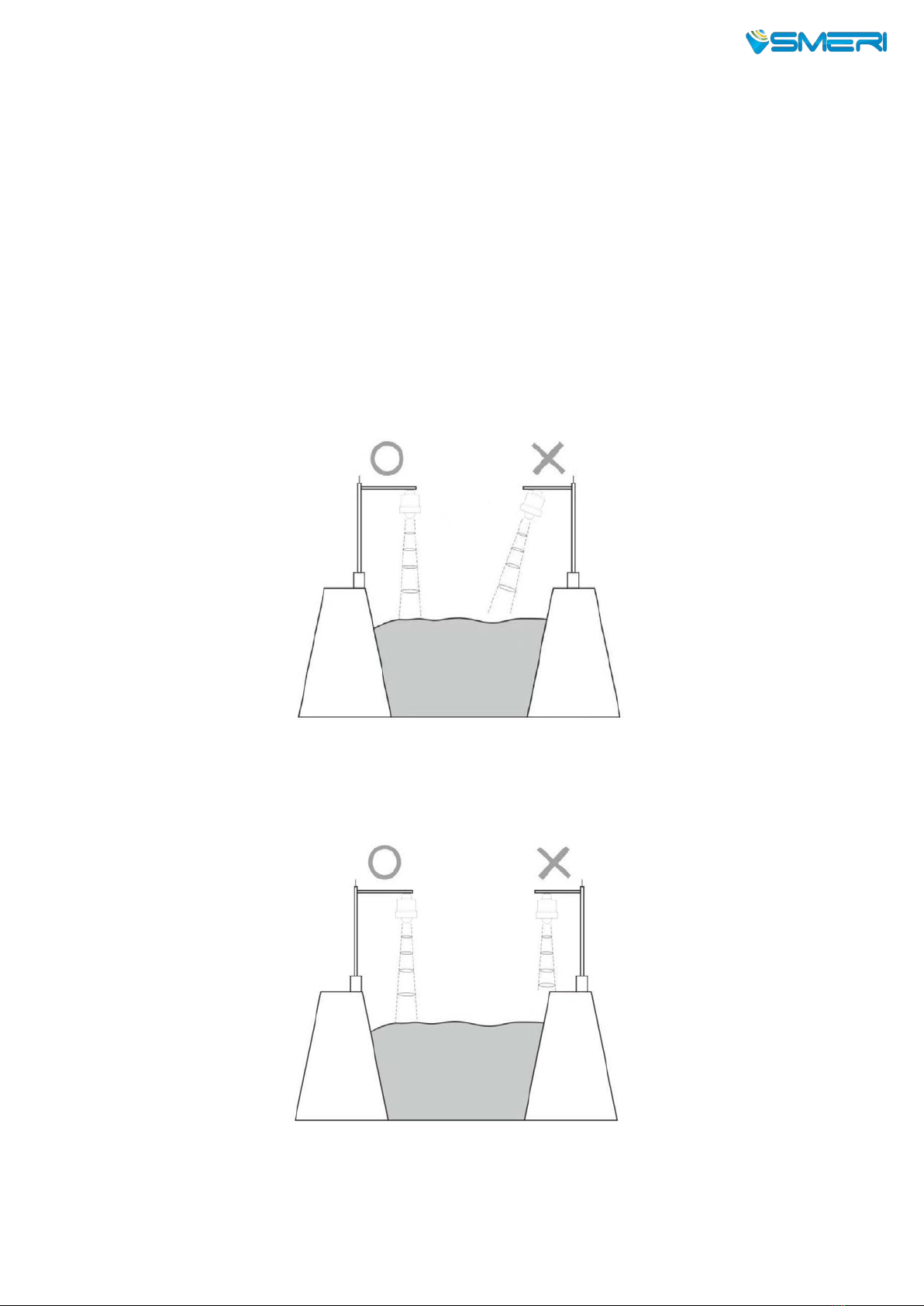
Two points need to be paid attention to during installation:
(1) Ensure that the meter is perpendicular to the water surface
(2) Avoid the emission beam irradiating the interference object and generating
false echoes.
Please check the following points for typical operating conditions.
Ensure that the water level sensor is installed perpendicular to the water surface,
and the tilt will weaken the received signal amplitude and affect the normal
ranging.
Make sure that there are no interfering objects within the beam range, such as
river banks.
MINIRADAR S-RD810/S-RD812
4
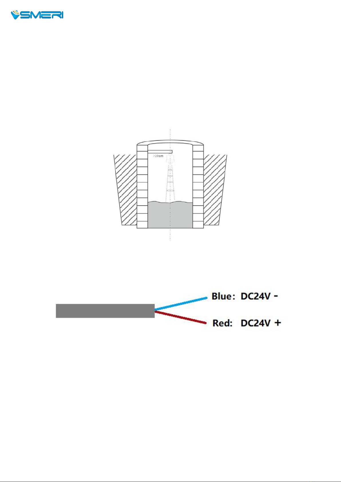
The installation of the instrument should be at least 20cm away from the side
wall, and the installation of the underground pipe network should be as close to
the center of the water well as possible, otherwise the well wall will easily
generate interference signals, which will affect the measurement and judgment,
as shown in the figure below.
3.Wiring
The radar water level sensor leads to two power lines, the red is connected to the
positive pole of the power supply, and the black is connected to the negative pole of
the power supply.
Note: the RTU is not included in the radar level sensor set.
MINIRADAR S-RD810/S-RD812

5
4. Debugging and Setting
RS-RD810
performs
liquid
level
measurement
tasks
according
to
the
settings,
which
can
be
modified
via
Bluetooth
and
APP
on
Mobile.
App RadarMe on Play Store for Android
4.1
Software
Setting
Open
the
APP
in
the
Mobile
Phone,
it
display
the
device
connection
interface,
as
shown
in
the
figure
below:
Click
the
name
of
the
device
to
be
set
to
enter
the
main
interface,
as
shown
in
the
figure.
See also the SERVICE pages on SMERI website:
tutorial for wireless programming
MINIRADAR S-RD810/S-RD812
6
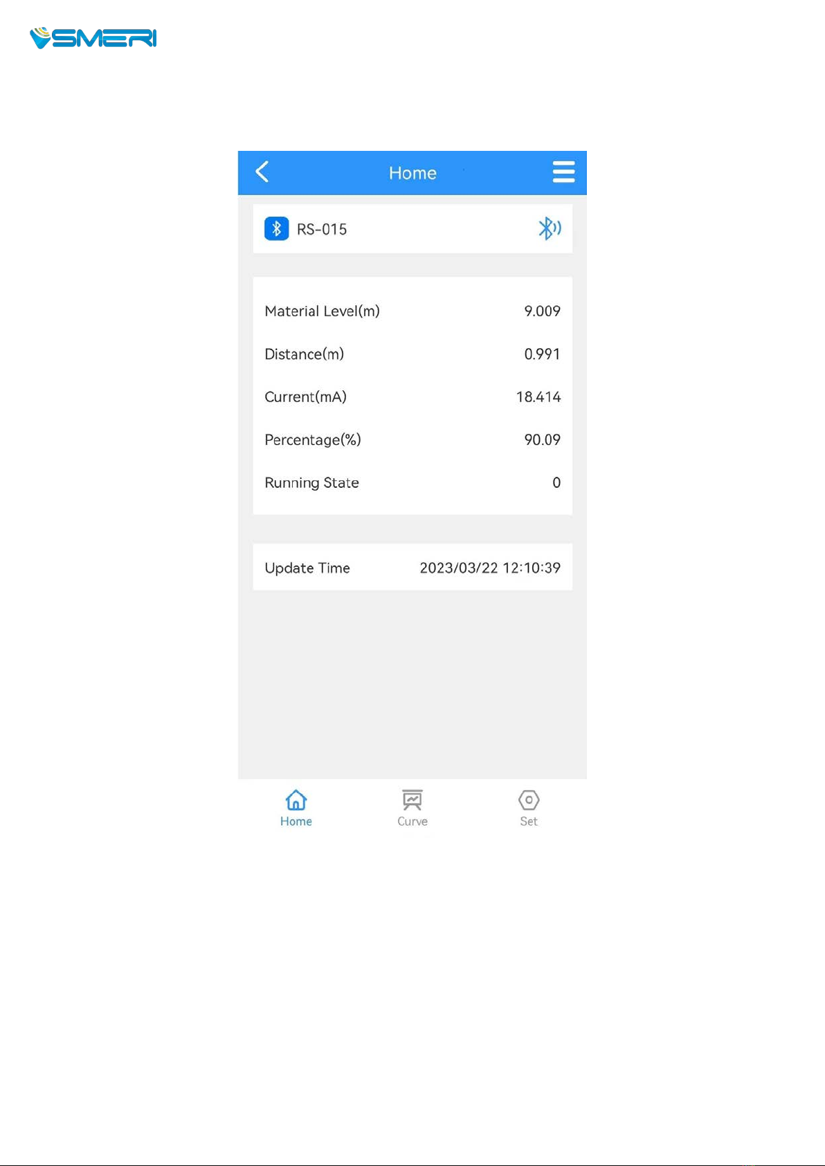
4.2 Main interface
Click the “Curve” button at the bottom of the screen to enter the echo
curve interface, as shown in the figure below:
MINIRADAR S-RD810/S-RD812

7
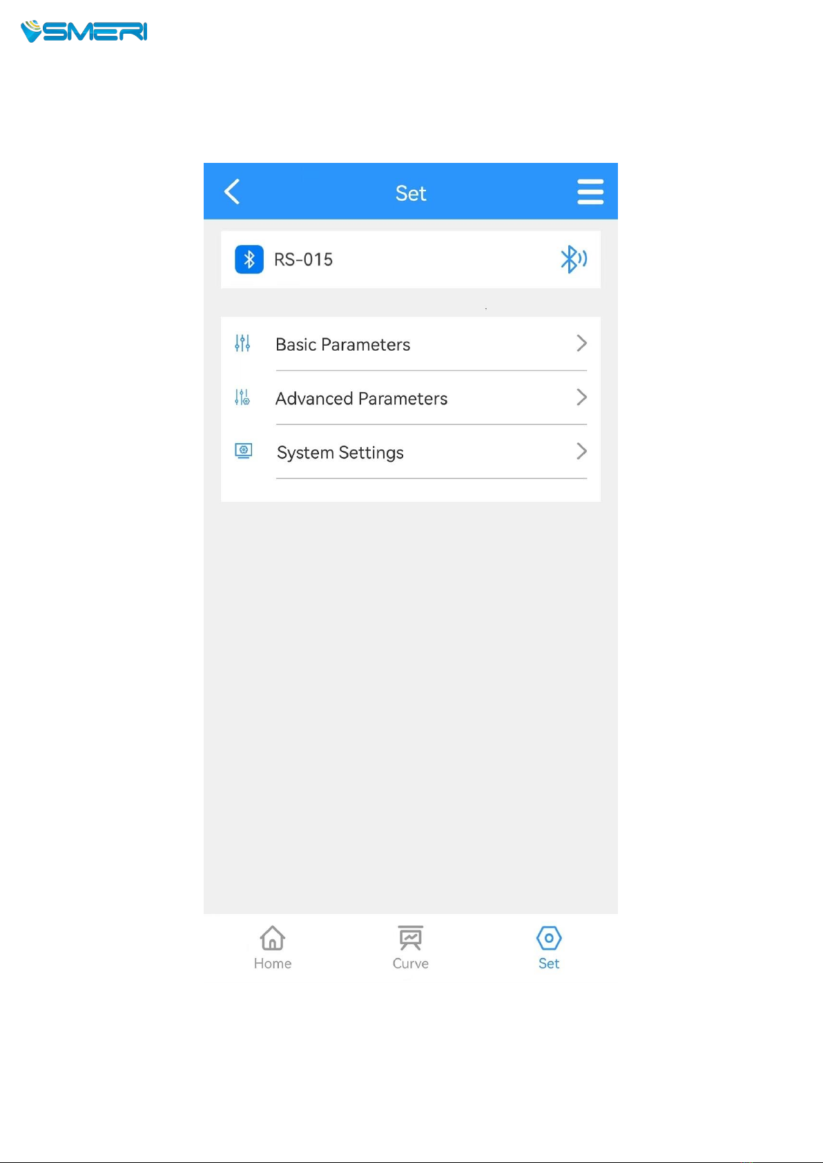
4.3 Echo Curve Interface
Click the “Set” button at the bottom of the screen to enter the
parameter setting interface, as shown in the figure below.
MINIRADAR S-RD810/S-RD812
8
4.4 Setting
MINIRADAR S-RD810/S-RD812
9
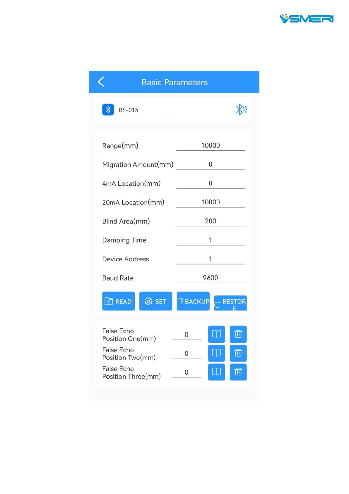
4.4.1 Basic parameters
Click the “Basic parameters” on the above interface, it shows below:
Set the “Range” according to the working conditions and directly click
the number input box behind to modify it.
The rest of the parameters are modified in the same way.
Click the “ Read” button to refresh the parameters.
MINIRADAR S-RD810/S-RD812

10
The 4mA location and 20mA location must be within the range, and the
relationship between the 4mA location/20mA location and the range is
shown in the figure below:
As shown in the figure, when the liquid level is lower than 4mA Location,
the main interface displays the liquids level as 0;
when the liquid level is higher than the 20mA location, the main
interface displays the liquid level value as the value of 20mA location.
Parameters definition--Basic setting
Range (500~50000) mm
Farthest distance that the gauge can measure.
Migration Amount
(-9999~9999) mm
According to specific working conditions.
4 mA Location
Liquid level corresponding to 4mA current output, Unit:mm.
20 mA Location
Liquid level corresponding to 20mA current output, Unit:mm.
Blind Area
Values range from 200mm~ measuring range, according to
specific working conditions. Unit:mm
Damping Time
In order to improve the stability of the measured output value,
a large [damping time ] can be set to stabilize the measured
value and increase the anti-interference ability.
For example: If the damping time is 10, the level of the
measured object undergoes a step change at time T, and the
measured output value follows the actual position of the
measured object after 10 seconds.
Device Address
Slave address in RS-485 communication, that is, the local
address (value range: 1-99, default value is 1 )
Baud Rate
The baud rate in RS-485 communication, the default is 9600.
Backup the parameters: After the working parameters are backed up, if there is an
error in manually modifying the parameters and the original working parameters are
forgotten, the working parameters can be “ restore” in the basic settings.
Restore the parameters: It is used to restore the backup parameters.
MINIRADAR S-RD810/S-RD812

5. Maintenance
Pay attention to keep the radar level sensor clean, try to be
waterproof,moisture-proof , anti-corrosion and avoid violent collisions and blows
from other objects.
Avoid direct sunlight on the main body of radar level sensor, keep away from
heat sources and pay attention to ventilation. If the ambient temperature exceed
the rated temperature,corresponding cooling protection measures should be
taken.
When the ambient temperature is too low, an instrument protection box or
other protective devices can be used for antifreeze protection, and keep the
radar dry.
The radar should be tested regularly.( the detection cycle is determined by the
user according to the specific situation)
6. Measurement problem analysis
Symptoms
Cause of issue
Solution
No display
Power Supply
Check whether the DC 24V voltage and
current meet the requirements or not.
Wiring
Check the wiring is correct or not.
Unstable Value
Strong fluctuating
Change the installation position of the
radar or reduce the fluctuation of the
object to be measured.
Weak Echo
Try angle alignment or rotate the radar
mount.
Strong
Electromagnetic
interference
Connect to the host to the ground or add a
shield.
SMERI srl
I 20057 Assago (MI) - Via Mario Idiomi, 3/13
Tel +39 02 5398941 - Fax +39 02 5393521
[email protected] - www.smerri.com
This manual suits for next models
1
Table of contents


