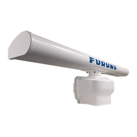
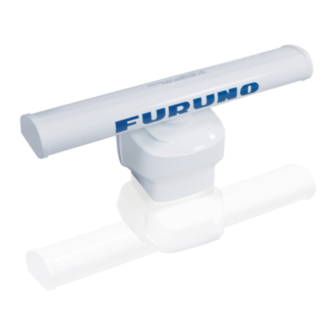
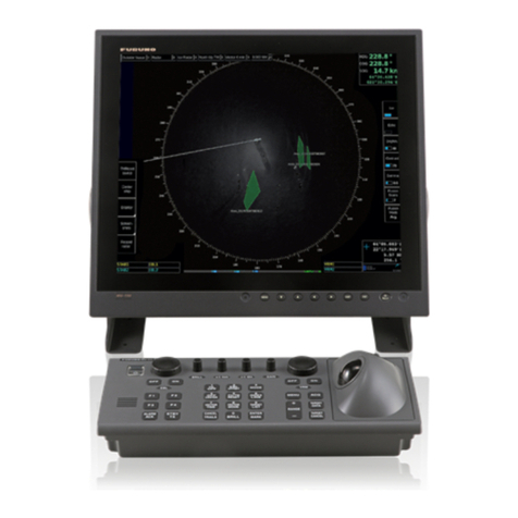
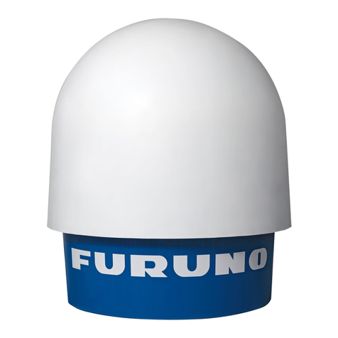
Furuno WR-2100 User manual

SSE-14-0023_17
INSTALLATION
MANUAL
Compact X-band Dual Polarimetric
Doppler Weather Radar
MODEL WR-2100
www.furuno.com

SSE-14-0023_17
i
IMPORTANT NOTICES
General
• This manual has been authored with simplified grammar, to meet the needs of international
users.
• The operator of this equipment must read and follow the descriptions in this manual. Wrong
operation or maintenance can cancel the warranty or cause injury.
• Do not copy any part of this manual without written permission from FURUNO.
• If this manual is lost or worn, contact your dealer about replacement.
• The contents of this manual and equipment specifications can change without notice.
• The example screens (or illustrations) shown in this manual can be different from the
screens you see on your display. The screens you see depend on your system configuration
and equipment settings.
• Save this manual for future reference.
• Any modification of the equipment (including software) by persons not authorized by
FURUNO will cancel the warranty.
• All brand and product names are trademarks, registered trademarks or service marks of
their respective holders.
How to discard this product
Discard this product according to local regulations for the disposal of industrial waste. For
disposal in the USA, see the homepage of the Electronics Industries Alliance
(http://www.eiae.org/) for the correct method of disposal.

SSE-14-0023_17
ii
SAFETY INSTRUCTIONS
The user and installer must read the appropriate safety instructions before attempting to install
or operate the equipment.
Indicates a hazardous situation which, if not avoided, will result
in death or serious injury.
Indicates a potentially hazardous situation which, if not
avoided, could result in death or serious injury.
Indicates a potentially hazardous situation which, if not
avoided,
can result in minor or moderate injury.
WARNING
Radio Frequency Radiation Hazard
The radar antenna sends the electromagnetic radio frequency (RF) energy. This energy can
be dangerous to you, especially on your eyes. Do not look at the radiator or near the
antenna when the antenna is rotating.
The distances at which RF radiation levels of 100 W/m 2 , 50 W/m 2 and 10 W/m 2exist are
shown in the table.
DO NOT go near more than 5.9m (Safety standard is 10 W/m 2 ).
Distance from Antenna
1.1m
2.8m
5.9m
Power flux density
100 W/m 2
50 W/m 2
10 W/m 2
WARNING
Do not open the radome.
Electrical shock can occur. Only qualified personnel should work inside the equipment.
Wear a hard hat and safety belt when mounting the Antenna
Unit.
Serious injury or death can result if someone falls from the radar antenna.
Do not use any other power except 100 to 240 VAC.
Connection of an incorrect power supply can cause fire or damage the equipment.
Turn off the power immediately if water leaks into the
equipment or smoke or fire is coming from the equipment.
Failure to turn off the equipment can cause fire or electrical shock.
Do not operate the equipment with wet hands.
Electrical shock can occur.
Do not disassemble or modify the equipment.
Fire or electrical shock can occur.
CAUTION
WARNING
DANGER

SSE-14-0023_17
iii
WARNING LABEL
Warning labels are attached to the equipment. Do not remove any label.
If a label is missing or damaged, contact us for the replacement.
Use only the specified power cable.
Fire or damage to the equipment can result if a different cable is used.
Use the power supply grounded certainly.
Electrical shock or defect of operation can occur.
When a thunderbolt is expected, do not approach a system or
do not touch a hand.
There is a possibility of receiving an electric shock.
A worker's safety is guaranteed although the measures which protect apparatus from
indirect lightning stroke serge are taken against this machine.
It is not a thing. Moreover, if a direct stroke is impressed, it may break down.
Attach securely protective earth to the unit.
The protective earth (grounding) is required to the AC power supply to prevent
electrical shock.
CAUTION
Do not put liquid-filled containers on the top of the equipment.
Fire or electrical shock can occur if a liquid spills into the equipment.
Establish space in the surroundings of apparatus as much as
possible.
It becomes a cause of performance degradation and failure.
Do not put any strong impact to LCD because of glass.
Serious injury may cause by broken glass.
Antenna Unit (radome)
Name: Radiation Warning Label
Type : 03-142-3201-0
number : 100-266-890-10

SSE-14-0023_17
Contents:
IMPORTANT NOTICES ....................................i
SAFETY INSTRUCTIONS................................ ii
System Configuration ...................................... vi
CHAPTER:
1. System Summary .........................................1
1.1. Type of radar bands ...........................1
1.2. Anatomy of Weather Radar................2
1.3. Mechanical tuning ..............................2
1.4. Multi-radar system..............................3
1.5. Other weather observation system ....4
1.6. Location of radar installation ..............4
1.7. Radar system certificate.....................5
1.8. Requirement of calibration .................5
1.9. Peripheral devices..............................6
2. Specification
2.1. Antenna Unit.......................................7
2.2. Signal Processing Unit .......................8
2.3. Mount Plate ........................................8
2.4. Display Unit ........................................9
2.5. Accessories ......................................10
2.6. Construction materials list ................ 11
2.7. Overall appearance ........................11
3. Prior confirmation
3.1. Confirmation items ...........................12
3.2. Power equipment ............................12
3.3. Measurements..................................12
3.4. LAN equipment.................................12
3.5. Storage box ......................................13
3.6. Peripherals equipment .....................14
4. Precautionary item......................................15
5. Construction
5.1. Mount plate.......................................16
5.2. Antenna Unit.....................................18
5.3. Signal Processing Unit .....................23
5.4. Display Unit ......................................26
5.5. AC Power strip ................................26
5.6. Open the radome temporary ..........27
6. Operation Test
6.1. Before cover .....................................28
6.2. After cover ........................................29
7. TeamViewer installation .............................30
8. DPU operation
8.1. File....................................................31
8.2. Setting
8.2.1. Service ...................................31
8.2.2. Management list .................... 38
8.3. Radar Operation .............................. 40
8.4. Initial setting of Azimuth................... 42
8.5. Total operation test .......................... 44
8.6. Shutdown the Radar System........... 44
8.7. Reboot SPU (PXI)............................ 46
8.8. PXI Pulse specification List.............. 46
8.9. Rainmap Parameter......................... 47
10. NI MAX .....................................................48
11. FWR
11.1. Upgrade .......................................49
11.2. Reboot SPU (PXI) ........................49
12. Create map file for RainMap
12.1. Required software ........................50
12.2. Web Browser ................................50
12.3. Display .........................................50
12.4 Overview .......................................50
12.5 Create a map ................................51
12.5.1. Cut maps ...........................51
12.5.2. Change color of map ...........64
12.5.3. Confirm a created map........70
12.5.4. Create a map license ..........73
13. Antenna pointing adjustment
13.1. Software preparation ....................74
13.2. PC setup ......................................74
13.3. Solar position ...............................74
13.4. Antenna position ..........................75
13.5. Advanced setting for solar
observation ..................................75
13.6. Process of antenna adjustment .76
13.7. Uninstall the software ...................77
13.8. Conclusion ...................................77
14. Outline drawing .......................................78
15. System diagram .......................................81
APPENDIX:
A. Lightning protection assessment .............. 83
B. Communication network ............................94
C. Storage media ...........................................97
D. UPS setting................................................98

SSE-14-0023_17
vi
System Configuration
The observation system consists of an Antenna Unit (Radome), a Signal Processing Unit (storage
box) , and a Display Unit (indoor unit) are shown below.
(1) Antenna Unit (radome)
The antenna, stored in the radome, turns to radiate the radio waves.
The radiated waves are backscattered by precipitation particles on the propagation path, return to
the antenna, and are processed by RF converter to transfer the signals to the Signal Processing
Unit .
(2) Signal Processing Unit (storage box)
Signal Processing Unit is stored in the storage box, and processes received signals digitally.
The digitally-processed signals are transferred to the Display Unit via 1000Base-T (LAN) .
(3) Display Unit (indoor unit)
To display and record the weather observation data.
Consumer must prepare the external storage device for recording the weather observation data if
necessary.
Note: The distance between entrance of ATU and SPU must be less than 3.5m if using 5m cables.
Indoor
)
AC100-240
UPS
USB cable
AC100-24
0
AC cable
(3) DPU
USB cable
Existing LAN /
Inter net / Modem
LAN cable
LAN
adapter
AC100-240
AC100-240
External data
storage device
AC cable
LAN cable
Signal cable
AC / Dsub cable
AC100-24
0
LAN cable
* All equipment except DPU in the indoor is option.
F U R U N O
(1) ATU
(2) SPU
Cables need 0.5m of
extra length inside SPU
for connecting to inside
devises
Cables need 1m of
extra length inside
ATU for connecting to
inside devises

SSE-14-0023_17
1
1. System Summary
RADAR (Radio Detection and Ranging) developed during World War II as a method to detect the
presence of ships and aircraft (the military considered weather targets as noise). Since WWII, there
have been many advances in radar technology (e.g., Doppler techniques) and it’s used on land, sea,
and in space for both research and operational needs.
1.1. Type of radar bands
There are several different categories according to the wavelength of using on radar in the world.
Type of bands are L, S, C, X, and K band.
L band radars: “L”for “long”. This band is mostly used for clear air turbulence studies. It
operates on 15-30 cm wavelength and a frequency of 1-2 GHz.
S band radars: “S”for “short”. It is not easily attenuated but useful for near and far/long range
weather observation. It operates on 8-15 cm wavelength and a frequency of 2-4
GHz. Some weather service uses it on a wavelength of just over 10 cm. The
drawback to this band of radar is that it requires a large antenna dish and a large
motor to power it. It is not uncommon for S band dish to exceed 7.62 m.
C band radars: “C”for “compromise”. The dish size does not need to be very large, so it is
affordable for TV stations. It operates on 4-8 cm wavelength and a frequency of
4-8 GHz. It is best used for short range weather observation because of the
signal is more easily attenuated by dry weather and rain. The frequency allows C
band radars to create a smaller beam width using a smaller dish. C band radars
also do not require as much power as S band radar.
X band radars: “X”came during XX2 for secret band. It uses smaller wavelength and it is more
sensitive and can detect smaller particles. It operates on 2.5-4 cm wavelength
and a frequency of 8-12 GHz. These radars are used for studies on cloud
development because they can detect the tiny water particles and also used to
detect light precipitation such as snow. X band radars also attenuate very easily,
so they are used for only very short range weather observation. Also, due to the
small size of the radar, it can therefore be portable like the Doppler on Wheels.
Most major airplanes are equipped with X band radar to pick up turbulence and
other weather phenomenon.
K band radars: “K”for “kurz = short in German”. This band is split down the middle due to a
strong absorption line in water vapor and it is similar to the X band but is just
more sensitive. It operates on 0.75-1.2 cm or 1.7-2.5 cm wavelength and a
corresponding frequency of 27-40 GHz and 12-18 GHz.
Figure 1: 3 general types of weather radar band

SSE-14-0023_17
2
1.2. Anatomy of Weather Radar
Antenna: The main purpose of the antenna is to focus the transmitted power into a small beam
and also to listen and collect the returned signal. This cassegrain antenna is designed
and manufactured with the highest performance, quality, low loss, low profile, and light
weight compared to other high gain antennas.
Radome: Protects the antenna from high winds, dusts, and rain.
Feedhorn: Directs the signal from the transmitter onto the antenna (also directs the return signal
from the antenna to the receiver).
Receiver: Detects the signal returned from a target.
Transmitter: Generates the microwave signal of the correct phase and amplitude. For a weather
radar, the wavelength of the signal is approximately 3cm. Solid state transmitters has
high performance assembled by many low-power amplifies. The modules are feed in
phase by power splitters. Its respective output powers (X-band is up to 500W) then are
in phase summed up to the complete transmit power. To achieve adequate range with
relatively low pulse power, the pulses are intra-pulse modulated often.
1.3. Mechanical tuning
This system observes the development of rain clouds, outputs the intensity of precipitation, the
speed of rain clouds (Doppler speed), and observes phenomena of rainfall. It has the efficiency of
high resolution rain observation, rain cloud, density, and speed observation. Solid-state
Transmitter replaces an aging device such as a magnetron.
Radome
Feedhorn
Receiver
Transmitter
Antenna
Ground clutter
Ice crystal snowflake
raindrop
hail
graupel
Rain gauge
70km

SSE-14-0023_17
3
A rapidly switched dual-polarization radar technique is used to obtain two-dimensional spatial
distributions of the statistical characteristics of the sizes and concentration of rain drops in rain.
These have been obtained using this high-resolution
wavelength radar, and the data have been used to
estimate rainfall rates within small volumes to a much
greater accuracy than is available from radar
measurements. The technique also gives a clear
distinction between ice particles and rain drops.
The region sampled by the radar increases with distance. The wider the beam, the greater the
likelihood of sampling a mixture of precipitation types, or the greater the likelihood of sampled both
inside and outside of a cloud. Obstacles frequently block a portion of the radar beam, resulting in
an artificially high power return.
Required accuracy on levelling:
Roughly 0.4 degrees is acceptable level but 0.4
degrees may cause 209.4m difference at 30km
point from radar. By that, the target accuracy is
to make 0.0 to 0.1 degrees.
1.4. Multi-radar system
Furuno provide multi-radar system. Use 3 radars to make 3 dimensions that makes possible to
detect precipitation faster and accurate with high resolution.
Even heavy rain does not leave blind
area using 3 radars.
Cumulonimbus
early detection
from low
altitudes
Start of
detection with
FURUNO radar
Start of detection with
conventional radar
Conventional
radar
FURUNO
radar
FURUNO radar
Conventional radar
Elevation Angle
Azimuth Angle
FURUNO radar detects cumulonimbus cloud faster
than conventional radar
To suggest it as a visible if the ground is lower by comparing a height of lower radar
beam and an altitude of ground surface.
Upper radar beam
Ground surface
Ground projection point
Middle radar beam
Lower radar beam
Radar unit
Mounting point
Observation area
Observation point

SSE-14-0023_17
4
1.5. Other weather observation system
There are several types of instruments to measure weather with pinpoint. Rain gauge,
Disdrometer, and Wind sensor are the major type of observation system.
For example, rain gauge is the most popular tool to know how much rain has fallen. The three
major types of rain gauges are the standard rain gauge, tipping bucket gauge, and weight gauge.
Further distinguishing aspects such as how they are set up and how they deliver data can be
made, though the basic operation of rain gauges does not usually vary from these primary rain
gauge types.
- Standard rain gauge: This instrument generally consists of a funnel connecting to a graduated
cylinder which is marked in scale to measure the amount of precipitation. When measurements
are taken, the height of the water in the small graduated cylinder is measured, and the excess
overflow in the large container is carefully poured into another graduated cylinder and
measured to give the total rainfall.
- Weight gauge: This instrument consists of a storage bin, which is weighed to record the mass.
The most representative of these gauges is tipping bucket. This bucket will output a pulse when
the rain tips into the bucket. It can found out the amount of precipitation by multiplying the bucket
volume and tipped number.
Besides that, there is an area measurement.
Instead of Radio Detection and Ranging (RADAR),
there is Sonic Detection and Ranging (SODAR) with
Light Detection and Ranging (LIDAR) to measure
wind speed and turbulence intensity. Use Remote
sensing devices (RSD) as measure devices to
measure the wind vector at various heights above
the ground. Both the horizontal and the vertical
components of the wind are recorded. The
recording is carried out by the intensity of a laser
beam (LiDAR) or a sound wave (SODAR) that is
backscattered by particles in the air. By determining
the Doppler shift, the wind speed vector can be
calculated from its components.
1.6. Location of radar installation
1. Confirm the observation region against the topography features:
It has to cover 1500 meter maximum altitude of its radius Rainfall forecast area. Therefore
there should not have any structure or object higher than radar around installation point.
200mm
Pinpoint sensor
Area measurement device
2.7 deg
GOOD
NOT GOOD
Observe area
NOT GOOD
GOOD
Side view
Top view

SSE-14-0023_17
5
2. While installing antenna on a rooftop of building or build a tall tower in urban area.
Mount the radar on the stand or tower; it must be higher than any surrounding interception
(building, structure) for radar observation. The tower must be designed strong enough against
the heavy storms and severe weather conditions.
On the other hand, crane or aerial work platform vehicle might be necessary to mount the
radar and install the stand. It has to consider for the space to place crane and move its arm.
3. Consider the lightning protection and grounding:
Provide a lightning rod near around a protection area to improve lightning protection
performance based on JIS A 4201, JIS Z 9290 and IEC 62305. Refer the APPENDIX A.
The protection systems should include surge protectors/absorber.
The grounding system will typically consist of an underground grid, radials, or rods which
provide a ground resistance of not more than 1 ohm. It should have a connection point at the
base of the tower. Refer the APPENDIX A for more detail.
4. Confirm the antenna surrounding:
Do not interfere to any surrounding antenna (e.g.: Broadcast, mobile (cell) phone station,
radio, BS/CS, and so on) and no obstacles should be around the antenna.
5. Securing of power supply:
Radar needs AC100V (up to 240V), single phase 50/60Hz with GND. The minimum electric
current must be installed for using 100V is 10A, and 240V is 4.2A.
6. Securing of telecommunication line:
Use telecommunication line for transferring a weather observation data and operating the
radar by remote. The minimum require speed to transfer all data in real time is 8 Mbps or
faster constantly. The wireless network might have enough speed just for operating system
but we recommend you to use fast speed network like fiber optic network if possible.
7. Building/ground structure:
A place where to install the radar must have load resistance and durability to build a tower or
stand. However to build the tower on the building or make a tower, some location might
requires the structural calculation from professional architect.
8. Consider against the human health affection:
Build the radar stand at least 2 meter height if install the radar where people can easy to
trespass. It also has to set up a sign board at the entrance or ladder where can access near
the radar.
9. Heating and cooling system:
Air conditioning is necessary for keeping the stability of the temperature for the room/cabinet
(rack) of DPU.
1.7. Radar system certificate
Most of the country might be necessary to take the certificate of operating radar as a radio station
from own country by law. It belong with the radio spectrum that many radio services provide
functions ranging from air traffic control to amateur radio operations. Although the radio frequency
spectrum is not a consumable resource, the use of a frequency at a given location usually
prevents that frequency from being used by others in the same geographic area. It needs of
exclusive geographic use to preclude harmful interference has led to current spectrum regulations
the establish spectrum use rules, such as granting licenses for spectrum use, and partitioning the
spectrum for share use between radio services.
The certification is approving such as Ministry of Internal Affairs and Communications (Japan),
Federal Communications Commission (USA), or Federal agencies of the country. It has to apply
right after the location for installing the radar is decided because it will take time to get certification.
Some place might take a year.
1.8. Requirement of calibration
Calibration is the activity of checking or measuring by comparison with a standard, the accuracy of
a measuring instrument of any type. It may also include adjustment of the instrument to bring it into
alignment with the standard.

SSE-14-0023_17
6
1.9. Peripheral devices
- External HDD (Hard Disk Drive): It is useful for saving data. Use USB3.0 connector type to
transfer the data without stress. Recommendation of using 6TB (possible to save data around
half year by compression)
- UPS (Uninterruptible Power Supply): Solution to avoid risk of DPU crash by instantaneous
power failure because of the trouble of electric power company, facility power, or natural
disaster such as thunderstorm. Purchase outlet ON/OFF selection type if possible to turn the
power ON/OFF to each device by remote operation via the internet.
Sample image:

SSE-14-0023_17
7
2. Specifications
2.1. Antenna Unit
Parameter
Descriptions
Remarks
Unit name
WR-2100-ATU
Operating Frequency
9.4 GHz band
Carrier Frequency
Maximum range
Max. observation level: 70km
Displayable observation level :
70km
Doppler measurement
Max. ±48m/sec
Power supply
100-240VAC, Single Phase, 50/60 Hz
Power consumption
Max. 350W
Rated Ampere
1.5-3.5A
Size
Φ1085mm×H1025mm
radome size
Weight
68kg (150lb)
Weight of radome only:
Upper 17kg, Bottom 9kg
Operating Temperature
-10 to +50 °C
Storage Temperature
-20 to +60 °C
Water & Dust proof
IPX5
Maximum wind survival
60.0m/sec
Occupied Band Width
60 MHz or less
Type of Emission
P0N(*1), Q0N(*2), V0N(*3)
Amplifier
Solid state module
Peak Power
100 W
each Horizontal and Vertical
Duty Ratio
Up to 12 %
Pulse Width
0.1 –50μs
Pulse Repetition
Frequency
600 –2500 Hz
Frequency Shift
2 –20 MHz
except P0N
Antenna Type
Cassegrain
Aperture Size
Φ750 mm
Antenna Gain
33.0 dBi
Antenna Polarity
Dual polarimetric
Vertical and Horizontal
Beam Width
2.7 degree
Both Horizontal and Vertical
Antenna elevation
rotate speed
Up to 60 deg/s
Antenna Rotation
Speed
0.5 to 16 rpm
Adjustable
Horizontal Scan Angle
360 degrees
Continuously-rotating
Vertical Scan Angle
-2 to 182 degrees
Adjustable
Resolution of Angle
0.1 degrees
Precision of Angle
0.2 degrees
*1 P0N : Sequence of pulses without modulation.
*2 Q0N : Sequence of pulses, frequency modulation within each pulse.
*3 V0N : Combination of P0N and Q0N.
- P0N is used for short range de tection.
- Q0N is used f or long range detection .

SSE-14-0023_17
8
2.2. Signal Processing Unit
Parameter
Descriptions
Unit name
WR-2100-SPU
Data Output*1
Rainfall intensity Rain (mm/h), Reflectivity factor Zh (dBZ),
Doppler velocity V (m/s), Doppler velocity spectrum width W
(m/s),
Cross polarization difference phase φdp (deg),
Specific differential phase KDP (deg/km),
Co-poral correlation coefficient ρHV, Differential reflectivity ZDR
Scan modes
PPI, Volume scan, PPI/RHI (Sector Scan also availiable)
Ground clutter Rejection
Enable
Data Correction
Distance attenuation, Rain attenuation, Excessive Doppler
velocity,
Suppression of signal returns from lan, Clutter suppression
Minimum receiving power
Under -110 dBm
Dynamic range
Above 75 dB
NF
Under 5.0 dB
A/D convert resolution
14 bit
Sampling frequency
125 MHz
Interface
LAN 1 port, Ethernet 1000 Base-T (Cat5e or better)
Power supply
100-240VAC, Single Phase, 50/60 Hz
Power consumption
Max. 650W incl. Storage box (Air conditioner)
Rated Ampere
2.7-6.5A
Size
W756mm×D300mm×H750mm
Weight
50kg (111lb) (include storage box w/ keyx2)
Operating Temperature range
-10 to +50 °C
Storage Temperature range
-20 to +60 °C
Water & Dust proof
IPX5
*1: Detail of processing by the main unit.
Notice of the data communication:
Condition of the data communication (Transfer efficiency: 50%)
Baud rate
Cycle (Data transmission possibilities)
1Mbps/min or more
4 elevations/ 5min.
4Mbps/min or more
2 elevations/ 1min.
8Mbps/min or more
4 elevations / 1min.
2.3. Mount Plate
Parameter
Descriptions
Unit name
84-001-1012-0
Size
900mm×900mm×t 10mm
Weight
18kg (39.7lb)

SSE-14-0023_17
9
2.4. Display Unit
Receive data from Signal Processing Unit (SPU) to indicate a picture of rainfall in real time.
Hardware
Parameter
Descriptions
Unit name
WR-2100-DPU
Power supply
100-240VAC, 50/60Hz
Power consumption
Max. 200W
Rated Ampere
0.8-2.0A
CPU
Core-i7 (3GHz) or better
RAM
8GB or more
Data storage device
500GB or more
OS
Windows 8.1, 64bit professional or better
Internal LAN
2 port, 1000base-T (Connect to SPU)
LAN Adapter
USB3.0 1000base-T adapter x1 (Access with outside PC)
(* Unnecessary if internal LAN x2 port are mounted on DPU)
I/O
USB2.0×2 port, and USB3.0×1 port minimum
Temp. range
+10 to +35 °C
Display Software
For weather observation system
Name
RainMap, RainPlay
Data indication
Rainfall intensity Rain (mm/h), Reflectivity factor Zh (dBZ),
Doppler velocity V (m/s), Doppler velocity spectrum width W (m/s),
Cross polarization difference phase φdp (deg),
Specific differential phase KDP (deg/km),
Co-poral correlation coefficient ρHV, Differential reflectivity ZDR
Status display
Indicate ATU and SPU status
File output
Save and output one scan period of data
For remote maintenance
Name
TeamViewer GmbH
Version
TeamViewer Host (For remote server) 9.0441
Function
Remotely operate the software, view and download the observation data.
Requirement
It must be connecting to internet
For monitoring the weather radar system connection
Name
NI MAX
Function
Monitor the connection between SPU, ATU, and DPU
Requirement
LAN connection to the SPU

SSE-14-0023_17
10
2.5. Accessories
Cables & Tube
Antenna Unit (radome) <-> Signal Processing Unit (storage box) cable
Descriptions
Length
Qty
Control cable
25pin cable (Both Dsub-25pin)
5m(*1)
1
Control cable
9pin cable (Both Dsub-9pin)
5m(*1)
1
Signal cable
3D-2W (Both SMA-P Connector)
5m(*1)
3
AC Power cable
VCTF 2sq 3core or equivalent
5m(*1)
1
Protective tube
PF tube conduit Inner diameter : 28 mm
10m(*2)
1
Accessories for installation
Items
Descriptions
Qty
M10x35 Hexagon Bolt
(w/ Split Lock Washers / Flat Washers)
Material : SUS304 (Fixed for radome)
12
M16x200mm Hexagon Bolt
Material : SUS304 (Fixed for radome and stand)
4
M16 Nut
Material : SUS304 (Fixed for radome and stand)
16
M16 Split Lock Washers
Material : SUS304 (Fixed for radome and stand)
8
M16 Flat Washers
Material : SUS304 (Fixed for lifting tool)
8
M16 Large Flat Washers
Material : SUS304 (Fixed for lifting tool and stand)
8
Drain tube
Set in between radome and mount plate
3
Accessories for maintenance
Items
Descriptions
Qty
M10 x400 Stud Bolt Steel
Holding the radome cover up above in order to access
inside the radome when maintenance
4
M10 Nut
Fix the length of stud bold for lifting up the radome
4
M10 Slip on Lock Nut
Holding the radome cover up above in order to access
inside the radome when maintenance
4
Philips Screwdriver #1
For PXI module
1
(*1) Fixed length.
(*2) Cut into two pieces to adjust a length of protective tube between ATU and SPU. Refer the note written
on page.v.(System Configuration).

SSE-14-0023_17
11
2.6. Construction material list (Local contractor/client supply)
Cables & Tube
Signal Processing Unit (storage box) --- Data Processing Unit
Items
Descriptions
Length
Qty
LAN cable
1000Base-T (STP Cat5e or better), Length depends on
measure value. Incl. LAN connector w/ cover
by measure
2
AC power cable
Shielded VCTF 2sq 3core or equivalent.
Incl. crimped Terminal
by measure
1
Protective tube
PF tube conduit Inner diameter : 28 mm
by measure
2
Basic construction equipment
Items
Descriptions
Qty
Heavy Duty Cable Tie (2 types)
Nylon 6/6 w/ weather resistance 140mm, 300mm
100
Silicone sealant or AC putty
Non-hardening, Electric insulation, for waterproof
qs
Basic construction tool
Items
Descriptions
SMA Torque wrench
74Z-0-0-21
SMA connector conclusion
Substitute : Caliber 5/16 inch or 8mm wrench
Hex key (Ball-head type)
M4 (3mm)
Ratcheting Wrench
M5 (8mm), M12 (19mm), M16 (24mm),
Adjustable wrenches (up to 30mm)
Socket Wrench
M10 (17mm) for fixing radome top/bottom
Exclusive Philips Screwdriver #1
For Dsub-25pin, PXI module
Philips Screwdriver #2
For M3, M4, M5, for Electric Filter
Slotted Screwdriver 3mm
Multiuse
Cable/Wire cutting scissors
Multiuse
Flat nippers
Multiuse
Wire Strippers
For electric wiring work
Ratchet Wire Crimper 2sq
For electric wiring work
LAN cable strippers
For LAN cable work
LAN Ratchet Crimper
For LAN cable work
LAN cable tester
For LAN cable work
Note: The stand of radar depends on installation environment, therefore consultation will be necessary.
2.7. Overall appearance
Refer the outline drawing of WR-2100 on chapter 15.

SSE-14-0023_17
12
3. Prior confirmation
3.1. Confirmation items
1. The mount plate must be installed properly for Antenna Unit (radome).
2. Power cable (AC100V-240V) must be laid safely. Minimum electric current must be installed
for using 100V is 10A, and 240V is 4.2A.
3. Power cable thickness should be selected depends on its length.
4. Frequency of AC power source must be 50Hz or 60Hz sin wave and single-phase current.
5. All engineers must wear the safety appliances such as a helmet, and safety shoes during an
installation of Antenna Unit. It is very dangerous that Antenna might hit a head by turning.
DO NOT look the antenna closer while radar is in operation. This energy can extremely
damage to the human body and especially to the eyes. Furthermore, DO NOT points the
antenna to the people closer while transmitting.
* The following table is shown the distance of transmit radio wave to be 100W/m2, 50W/m2, and
10W/m2. The value of Safe standard is 10W/ m2, therefore do not go closer than 5.9m.
Range from Antenna [m]
1.1m
2.8m
5.9m
Power Flux Density [W/m2]
100W/m2
50W/m2
10W/m2
3.2. Power equipment
This equipment must need 1KVA x1 line of power, with ground outlet (3 pin type)
3.3. Measurements
Items
Descriptions
Remarks
Digital Multimeter
Voltage
AC : 85 to 240 V
DC : 1 to 50V
Current
AC : 1 to 10 A
DC : 1mA to 1A
Resistor
0.1 to 10M ohm
Tester
Lead Cables
Angle Meter
Measurement range : ≧45deg
Accuracy : within ±0.2deg
Zero adjustment
vertical angle
of RADAR
3.4. LAN equipment
1) Use Cat5e (or better grade) of 1000Base-Tx LAN cable for transferring the data from the
Display Unit to output equipment.
2) Be prepared High speed broadband (approx.100Mbps) for using remote maintenance.
*Low speed broadband may cause slow access on remote to support a system.

SSE-14-0023_17
13
3.5. Storage box
Air Conditioner
Type
Outdoor Storage box Lateral mounting
Cooling capacity*1
100W
Rated voltage*2
Single phase, 100V AC to 240V AC (50/60Hz)
Current consumption*3
Rated
0.8A(at 100VAC), 0.4A(at 200VAC)
Max.
1.0A(at 100VAC), 0.5A(at 200VAC)
Starting current
4.0A(at 100VAC), 8.5A(at 200VAC)
Power consumption
Rated
74W
Max.
97W
Working temperature*4
Inside : -10 to +50 °C
Outside : -20 to +50 °C
Max. working humidity*4
Inside : 85%RH
Outside : 95%RH, Free from condensation
Temperature setting range
for cooling operation
+25 to +45 °C
(initial setting ON +35 °C / OFF +30 °C)
Setting temperature for
heating
ON +5°C / OFF +10°C(Fixed)
Temperature and humidity
for keeping condensation
free
Not exceeding +35 °C , 70%RH
Outer covering material/
surface finish/Color
SUS304/Powder coating/Beige (5Y7/1 equivalent)
Louver material/Color
Polycarbonate/Beige (5Y7/1 equivalent)
Function
・High temperature detection
・Maintenance reminder
・Fan motor stop error detection
・Temperature sensor error detection
・Abnormal temperature at power supply
・Thermoelectric module error detection
・Power supply error detection
Noise (Characteristic A)
50dB
Protective category*5
IP55 (Category 2)
Safety/Environmental
standard
-/RoHS
Dimensions (in mm) *6
W270 × H340 × D184
Weight
8.9kg
*1: Nominal value when temperatures both inside and outside the enclosure are 35°C
*2: Nominal heating capability when temperatures both inside and outside are +5°C.
*3: Values at 35°C temperature both inside and outside are indicated in "Rated" and values at 0°C
both inside and outside are indicated in "Max".
*4: Use only within the specified temperature and humidity range.
*5: This indicates the value for an enclosure to which air conditioner is mounted, provided that it has
equivalent or more protectively, and not for air conditioner itself.
*6: Louvers and guards are excluded.

SSE-14-0023_17
14
3.6. Peripherals equipment
The purposes of using these peripherals are for remote control:
1. Wired router
Function
Connect with an external network
WAN port
10/100/1000BASE-T, 1 port, MDI/MDI-X auto switch
LAN port
10/100/1000BASE-T, 4 port or more, MDI/MDI-X auto switch
Input voltage
AC100V-240V, Single phase, 50/60 Hz
Remarks
YAMAHA RTX810 or equivalent
2. SW HUB
Function
Connect with LAN
LAN port
10/100/1000BASE-T, 5 port or more, MDI/MDI-X auto switch
Input voltage
AC100-240V, Single phase, 50/60 Hz
Remarks
ELECOM EHC-G05MN-HJ or equivalent
3. Uninterruptive Power Supply
Function
Automatically shut down after 10 minutes operation during a power
failure
Output voltage
More than 1,000VA
Input voltage
AC100-240V, Single phase, 50/60 Hz
Remarks
APC Smart-UPS series w/ network or equivalent
4. External data storage device
Function
Save scan data
Capacity
3TB or more
Interface
USB3.0/2.0 x 1 port
Input voltage
AC100-240V, Single phase, 50/60 Hz
Remarks
WD 3TB or equivalent
5. Remote Power Controller
Function
Reboot the power of equipments by remote
Capacity
2-4 individual outlet power control (ON/OFF/Reboot/Schedule)
Interface
10BASE-T/100BASE-TX RJ-45X1, RS232
Input voltage
AC100-240V, Single phase, 50/60 Hz
Remarks
AVIOSYS IP POWER series or equivalent
Other manuals for WR-2100
1
Table of contents
Other Furuno Radar manuals

Furuno
Furuno FR-1908V-BB User manual

Furuno
Furuno FRS1000 Operator's manual

Furuno
Furuno FAR-3230S-BB User manual

Furuno
Furuno DRS4D-NXT User manual

Furuno
Furuno FAR-3320SW User manual

Furuno
Furuno FAR2137S/12 User manual

Furuno
Furuno FAR-3210 User manual

Furuno
Furuno FCR-1010 User manual

Furuno
Furuno FR-2105 User manual

Furuno
Furuno WR110 User manual

Furuno
Furuno WR-2100 User manual

Furuno
Furuno FOIL-200 User manual

Furuno
Furuno WR2120 User manual

Furuno
Furuno FR-1500 MARK-3 User manual

Furuno
Furuno DRS6A-NXT User manual

Furuno
Furuno WR110 User manual

Furuno
Furuno FCR-1030 User manual

Furuno
Furuno DRS12AX X-Class User manual

Furuno
Furuno FAR-3220Z User manual

Furuno
Furuno DRS4A User manual