Traffic Logix SafePace 700 User manual


2
Copyright ©2014-2016 Traffic Logix® Corp. SafePace® 700: Installation Manual v1.4
Table of Contents
Introduction .......................................................................................................................... 3
Overview............................................................................................................................... 4
Site Selection......................................................................................................................... 4
Positioning the Sign............................................................................................................... 4
Sign Assembly ....................................................................................................................... 6
Mounting the sign ................................................................................................................. 7
Power options ....................................................................................................................... 8
AC power (standard model)............................................................................................................8
Battery power................................................................................................................................9
Solar power .................................................................................................................................10
Mounting the Solar Panel ...................................................................................................................................10
Wiring the Solar Panel to the Sign ......................................................................................................................11
Turning the Sign ON and OFF ............................................................................................... 13
Operating your sign............................................................................................................. 13
Maintaining your sign ......................................................................................................... 14
Replacing key internal sign components .......................................................................................14
Warranty ............................................................................................................................ 15
Technical Support ................................................................................................................ 16
3
Copyright ©2014-2016 Traffic Logix® Corp. SafePace® 700: Installation Manual v1.4
Introduction
Congratulations on your recent purchase of a Traffic Logix® SafePace® radar sign. They are a perfect
choice for municipalities, residential neighborhoods, schools, police departments, private or gated
communities, corporate campuses, schools and construction sites. These full featured signs are
extremely versatile with the options you need at remarkably low pricing.
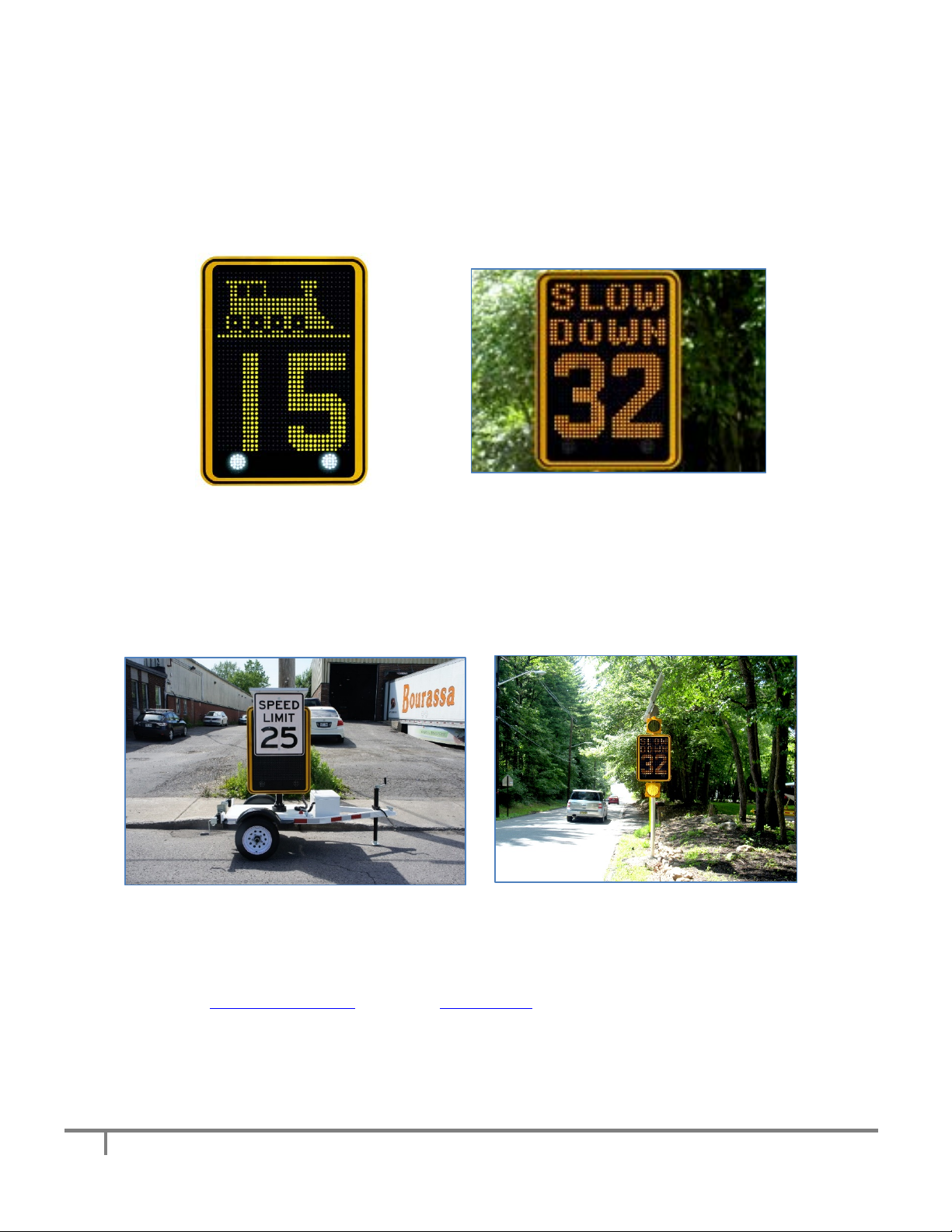
Figure 1, SafePace® 700 - Vertical driver feedback sign
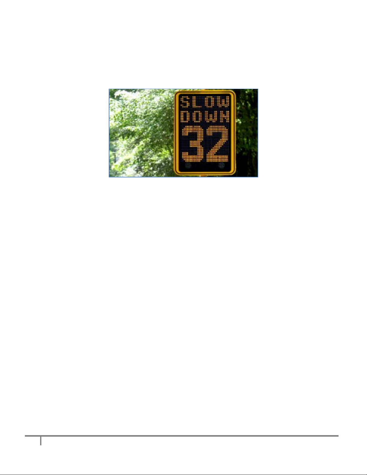
The SafePace® 700 radar sign offers two rows of customizable text with extra-large 18 inch LED digits.
You can display the message of your choice including animated text or graphics while displaying vehicle
speeds in bright, large digits that motorists can see even from a distance. It can also be transported and
deployed with the SafePace® Cruiser LT, or can be combined with the SafePace® Beacon system.
Figure 2, SafePace® 700 Cruiser LT (left) and SafePace® Beacon System (Right)
This document is a guide to the installation of the radar sign to the side of a pole. For more information
about the SafePace® 700 Cruiser LT and/or the SafePace® Beacon System, please visit the documentation
section in the customer downloads area of our Traffic Logix® website for more information.
4
Copyright ©2014-2016 Traffic Logix® Corp. SafePace® 700: Installation Manual v1.4
Overview
This guide provides installation instructions for mounting and wiring your SafePace® 700 radar sign. Also
covered, are wiring instructions for different power options, recommendations for site selection and
positioning of the sign, and further details on operation and maintenance.
SafePace® 700
Site Selection
Site selection varies with the application in which the radar sign is being used. The following guidelines,
however, should generally be adhered to:
i) Choose a position where the line of sight from the radar sign to the vehicle will be
uninterrupted. Consideration should be given to how the location may develop with time. The
following types of questions should be considered:
a. Will any trees grow directly in the line of vision?
b. Is it likely that road traffic signs will be erected in a position that could obstruct the field of
view?
ii) The radar sign should be installed directly adjacent to the lane of cars it is targeting since an
interfering lane of traffic may cause inaccurate speed readings.
iii) The structure that the radar sign is mounted to should be stable and firm. Avoid structures that
are likely to be affected by wind or rain. The suggested pole type for installation is either a 14-16
foot, 4 inch diameter circular metallic pole or a 4” x 4” square wooden pole.
Positioning the Sign
Similar to other road signs, the SafePace® 700 radar sign should be installed near the closest lane of
traffic, although off the actual road. The recommended height of the lower edge of the radar sign is
approximately 7 feet above the surface of the road.
The display should be turned towards oncoming traffic so that it is clearly visible to approaching drivers
(see Figure 3). The maximum detection range of the sign is 1,200 feet and varies based on the line of site
(see Figure 4).

5
Copyright ©2014-2016 Traffic Logix® Corp. SafePace® 700: Installation Manual v1.4
Figure 3, Symbolic Location
Figure 4, Zone of Detection
Range of
Detection up to
1,200 ft.
6
Copyright ©2014-2016 Traffic Logix® Corp. SafePace® 700: Installation Manual v1.4
Sign Assembly
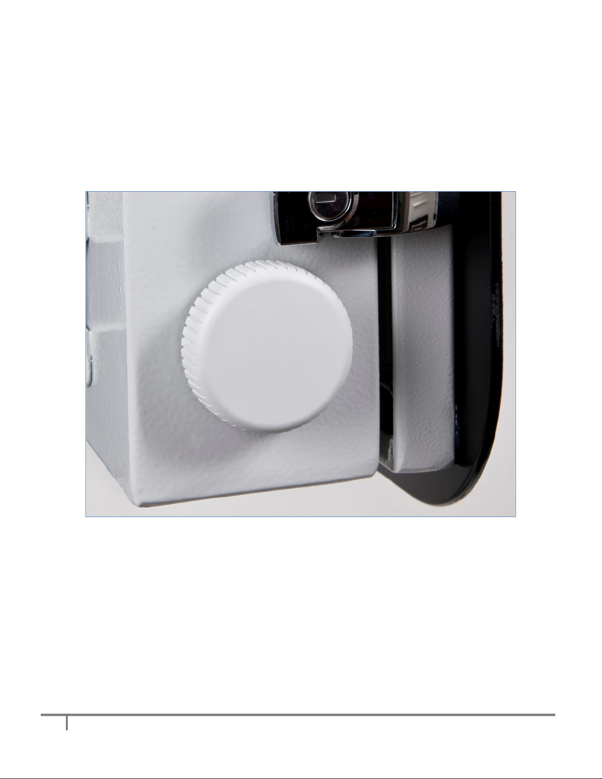
The SafePace® 700 radar signs come almost fully assembled. To prevent breakage during shipping, the
two waterproof breathers which are mounted diagonally on either side of the sign (see Figure 5 below)
are shipped uninstalled inside of the sign. These breathers allow only airflow, not moisture, to circulate
throughout the sign which prevents condensation and overheating. Remove the breathers from their
shipping bag and install by inserting them into the pre-cut mounting holes and securing with the
supplied rubber washer and nut.
Figure 5, Waterproof Breather

7
Copyright ©2014-2016 Traffic Logix® Corp. SafePace® 700: Installation Manual v1.4
The sign comes standard with banding brackets. If not already factory installed, mount the supplied
banding brackets to the top and bottom of the rear of the radar sign with the supplied screws (see
Figure 6 below).
Figure 6, Standard Banding Bracket Mounted Directly to Sign
Mounting the sign
The SafePace® 700 radar sign and optional solar panel should optimally be mounted on a 14 - 16 foot
pole. Insert the supplied stainless steel banding straps into the brackets and fasten the sign to the pole.
Tighten with a nut driver until secure (see Figure 7). Once secured, the sign is ready to be powered for
use.
Figure 7, Sign Secured to a Pole with Banding Strap
8
Copyright ©2014-2016 Traffic Logix® Corp. SafePace® 700: Installation Manual v1.4
Power options
The SafePace® 700 radar signs can be powered in several ways:
AC power (standard model)
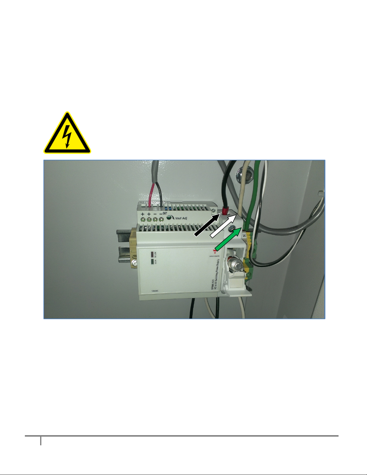
AC powered signs are equipped to accept 100-240 volts AC. The incoming AC power is converted to 12
volt DC to power the sign. For these signs the regulated power supply comes already pre-wired, and
your sign is ready to operate once it is mounted and wired to the incoming power supply.
WARNING: ELECTRICAL SHOCK HAZARD
To avoid serious injury or even death, all electrical wiring should be performed by a
qualified and professional electrician in accordance with local electrical codes.
Mishandling of electrical wiring may also result in damage to the unit which may
void product warranty.
Figure 8, AC Power Converter and Fuse Breaker
The Line (BLACK) and Neutral (WHITE) wires of the incoming power supply should be connected to the
marked terminals.
The GROUND wire (usually GREEN), should be connected to the GREEN/YELLOW terminal (see Figure 6
above).
9
Copyright ©2014-2016 Traffic Logix® Corp. SafePace® 700: Installation Manual v1.4
Battery power
Battery powered signs can accommodate up to six 12 volt DC lead acid batteries. These batteries when
fully charged, can power the sign up to 2 weeks (depending on traffic volume and environmental
factors).
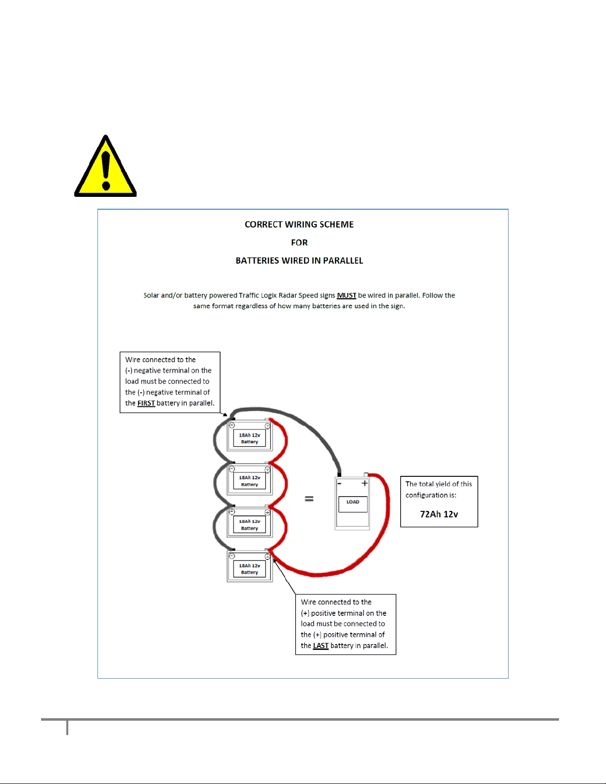
ATTENTION:Proper battery care and maintenance is required. To prevent damage to
the sign, please replace the batteries every TWO years. Improper care and
maintenance of batteries may void product warranty. Batteries should always be wired
in PARALLEL as depicted in Figure 9 below:
Figure 9, Wiring Signs in Parallel

10
Copyright ©2014-2016 Traffic Logix® Corp. SafePace® 700: Installation Manual v1.4
Solar power
Solar-powered signs can be powered using a combination of solar and battery
power. The solar panel powers the sign when exposed to sunlight while at the
same time charging batteries to provide a power backup for night-time and
cloudy day use.
A 135 Watt solar panel comes standard with the SafePace® 700 radar sign and
is quick to install and should suffice for most installations in areas with extended winters and below
average hours of sunshine.
Mounting the Solar Panel
The solar panel should be mounted at the highest point on the pole. Mount the panel using the supplied
solar panel bracket (see Figure 11 below) and please follow the instructions provided by the
manufacturer which are supplied in the bracket’s packaging.
Figure 10, Solar Panel Figure 11, Solar Panel Mounting Bracket
The two-part bracket allows for full adjustment in order to best position the panel towards the sun. It is
optimal to position your solar panel towards due Solar South (not magnetic South), if you are in the
northern hemisphere and towards due Solar North (not magnetic North) if you are in the southern
hemisphere. Regardless of whether you are in the northern or southern hemisphere, Solar North/South
is the position of the sun in the sky at exactly the midpoint between sunrise and sunset.
The solar panel should be angled 15 degrees above the latitude of the installation site which you can
readily ascertain from mapping software or for free from mapping and travel direction websites on the
internet.
For example, if the latitude of the installation site is 45 degrees
then the solar panel should be installed at an angle of 60
degrees, as shown in Figure 12.
Figure 12

11
Copyright ©2014-2016 Traffic Logix® Corp. SafePace® 700: Installation Manual v1.4
Wiring the Solar Panel to the Sign
As shown in the following images, the solar panel and the sign come pre-wired with quick connectors to
allow for a simple installation. Each of the cables from the sign can only be connected to the
corresponding connector on the solar panel.
Figure 13, Panel connectors Figure 14, Sign connectors
Insert the connectors from the sign into the corresponding connectors from the solar panel as shown
below (Figure 15).
Figure 15, Connectors partially inserted
Slide the connectors together until you hear a click and you can no longer slide them apart easily. Once
connected the cables should look like the following:
Figure 16, Sign and Panel cables connected
12
Copyright ©2014-2016 Traffic Logix® Corp. SafePace® 700: Installation Manual v1.4
WARNING: Before ever doing any maintenance on a sign, it is critical that the power
is first turned off. This will prevent accidental electrical shock that can be fatal and
that can also damage electrical components.
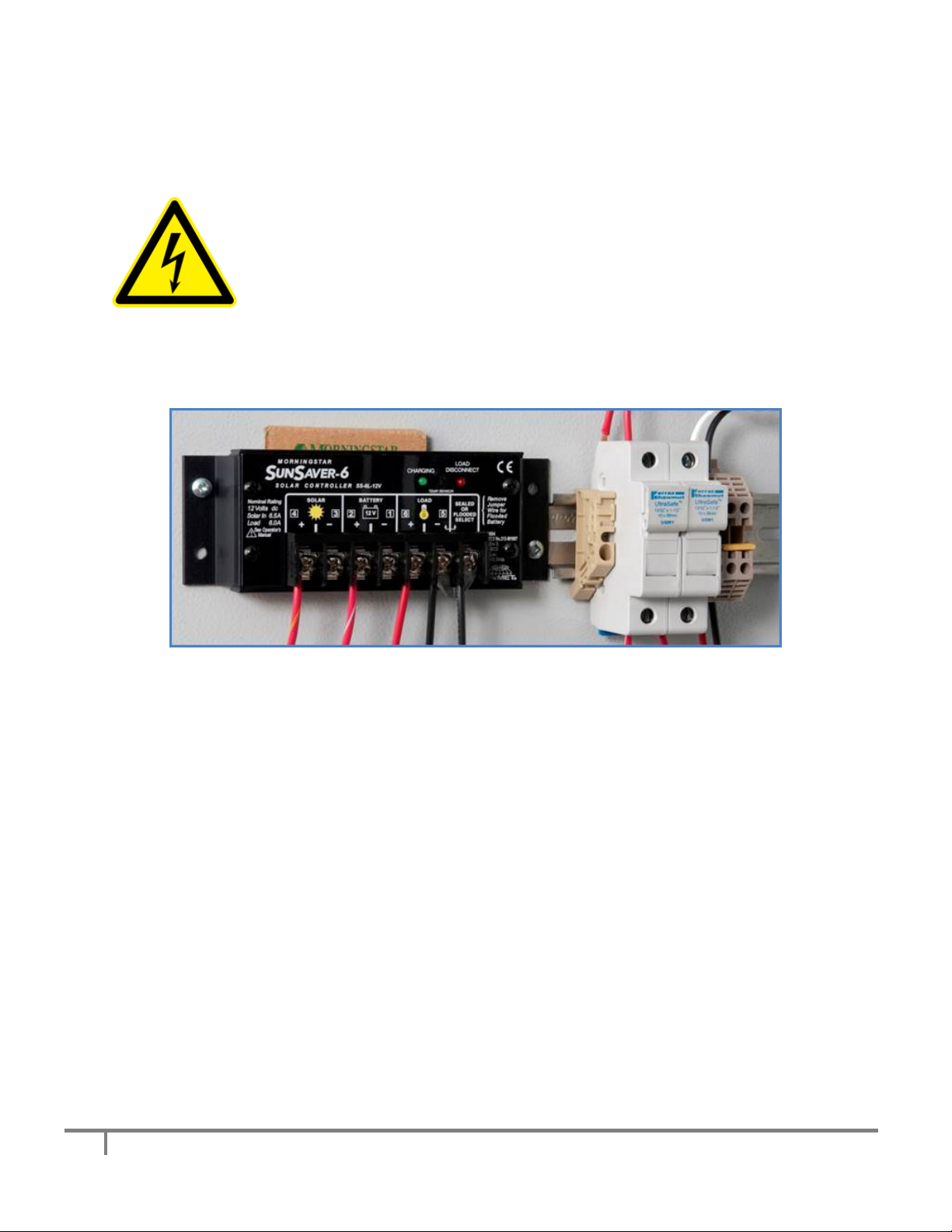
The solar power generated by the solar panel is regulated by a SunSaver voltage regulator (Figure 17
below). This voltage regulator will be completely wired and configured when you receive the sign, so
you do not need to make any changes to it.
Figure 17, SunSaver-6 Voltage Regulator
13
Copyright ©2014-2016 Traffic Logix® Corp. SafePace® 700: Installation Manual v1.4
Turning the Sign ON and OFF
There is no ON/OFF switch installed in the sign. The sign will, rather, immediately power on once the
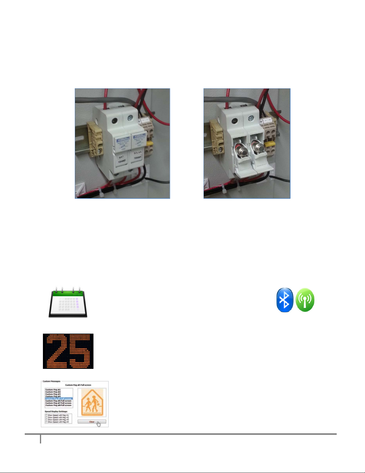
power source is connected and the fuse breakers are closed. All fuse breakers should be closed when
the sign is in operation, as shown below.
Figure 18, Fuse breakers closed Figure 19, Fuse breakers open
The solar panel breaker need not be closed to power the sign (assuming there is enough charge in the
batteries alone to power the sign); the open breaker, though, will prevent the batteries from being
recharged by the solar panel. To turn the sign off, simply open both the fuse breaker for the batteries
and the solar panel on the solar/battery models and the fuse breaker on the AC models.
Operating your sign
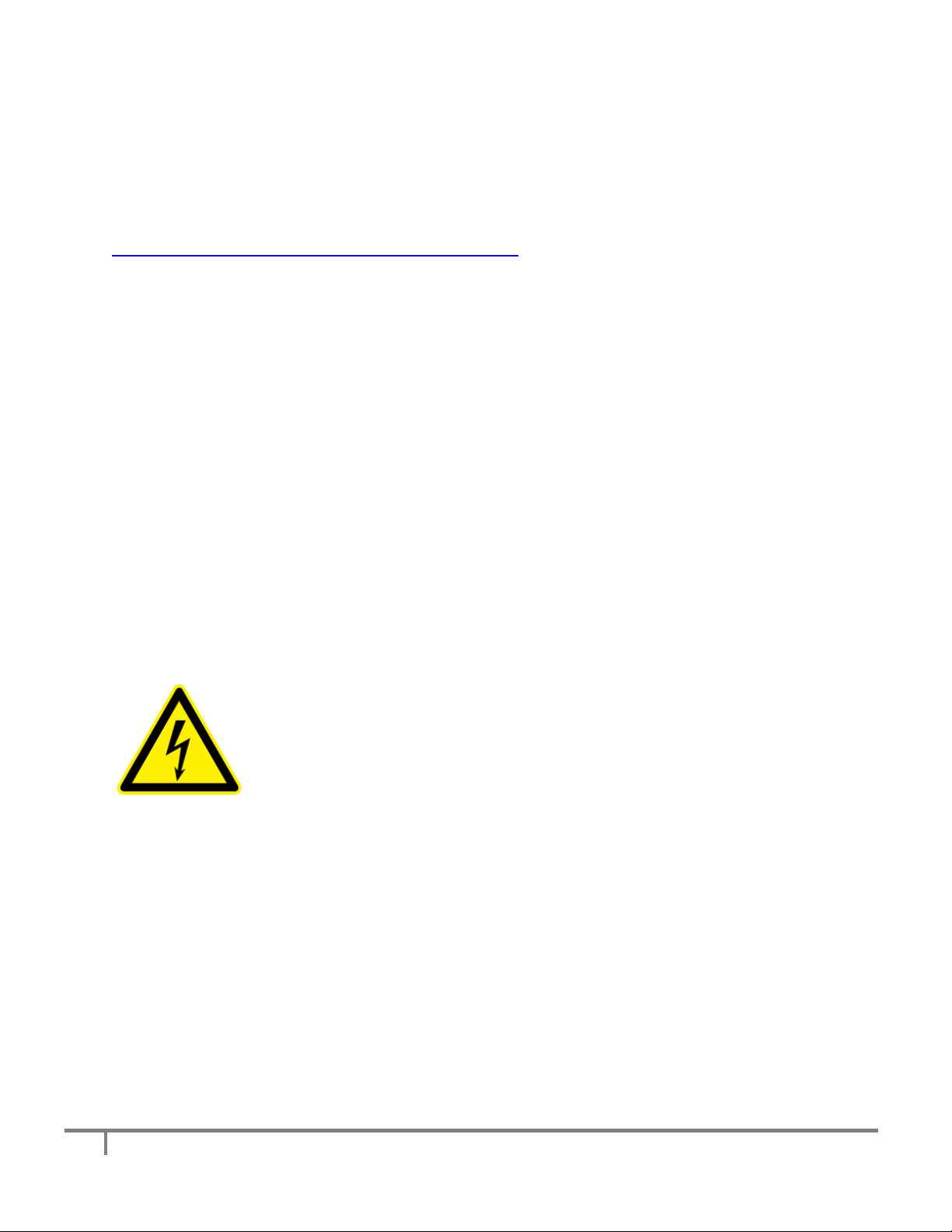
Once your sign is mounted and powered, you can connect to,
and manage, it via Bluetooth with our easy to use SafePace®
Pro application. You can also manage your sign remotely using
SafePace® Cloud, if you selected that option.
Depending where the sign has been shipped, your sign has been pre-programmed
to display speeds measured in kilometres or miles. The sign features a MUTCD
compliant radar speed display with two rows of LEDs for text and graphics and
extra-large 18" digits displaying vehicle speed.
Choose any message, graphic, or animated text using the standard library
provided or create your own library of custom messages to upload and
display.
14
Copyright ©2014-2016 Traffic Logix® Corp. SafePace® 700: Installation Manual v1.4
For more information on operating your sign with SafePace® Pro, refer to the SafePace® Pro User
Manual. For more information on operating your sign with SafePace® Cloud, refer to the Web Director
2.0 User Guide.
You can get the latest version of all manuals at:
http://trafficlogix.com/customerarea/customerdownloads
Maintaining your sign
Replacing key internal sign components
The SafePace® 700 radar speed sign are comprised of the following key electronic components (and
respective quantities):
•Controller Card (1)
•Radar Head (1)
•Battery (1) + Solar charger (1) - for signs powered by solar with rechargeable battery
•AC Power convertor (1) - for AC powered sign configuration
•Speed Violator Strobe PCB (2)
•LED Message Board PCB (20)
•BlueFin Bluetooth Controller (1)
•VMFin VM Controller (1)
•SIMFin GSM/GPRS Controller (1) - for SafePace® Cloud signs
•Ambient Light Sensors (2)
WARNING: Before ever doing any maintenance on a sign, it is critical that the
power is first turned off. This will prevent accidental electrical shock that can be
fatal and that can also damage electrical components.
*If you suspect that you require a replacement of any of the above-mentioned components, please call
Technical Support. If necessary, a Diagnostic Toolbox can be sent out to help trouble-shoot any issues
you may be having.

15
Copyright ©2014-2016 Traffic Logix® Corp. SafePace® 700: Installation Manual v1.4
Warranty
Subject to the following conditions, Traffic Logix Corporation (“Traffic Logix”) warrants that the
SafePace® 700 Speed sign (the “Product”) is free from defects in materials and workmanship. This
limited warranty begins on the invoice date of your purchase of the Product and extends:
•For TWO (2) calendar years on the radar sign, and
•For ONE (1) calendar year on the batteries.
This limited warranty extends only to the original purchaser of the Product when purchased either
directly through Traffic Logix or through an authorized Traffic Logix distributor and is not assignable or
transferable to any subsequent purchaser or end-user. Traffic Logix’s obligation and liability under this
warranty are expressly limited to repairing or replacing, at Traffic Logix’s option, defective products. In
no circumstances shall Traffic Logix’s liability, whether in contract or tort, under any warranty, in
negligence, or otherwise, exceed the amount of the purchase price of the product. Traffic Logix shall not
be liable for special, indirect, or consequential damages of any kind. This warranty does not cover
damages resulting from normal wear and tear, incorrect installation or operation, use other than for the
product’s intended purposes, vandalism, and extraordinary environmental circumstances. Traffic Logix
reserves the right to charge for these damages to the product at rates normally charged for repairing
such products not covered under this warranty. Damages resulting from any physical changes or
alterations made to the product other than Traffic Logix will render this warranty VOID. Using any parts
or accessories not supplied or approved by Traffic Logix, such as battery chargers, will further render the
warranty VOID.
Traffic Logix neither assumes, nor authorizes any person to assume for it, any other liability in
connection with the sale of the Product, and there are no agreements or warranties collateral to or
affecting this limited warranty. THE LIMITED WARRANTY SET FORTH IN THIS AGREEMENT IS THE
EXCLUSIVE AND SOLE WARRANTY APPLICABLE TO THIS PURCHASE. ALL OTHER WARRANTIES, EXPRESS
OR IMPLIED, INCLUDING, BUT NOT LIMITED TO THE IMPLIED WARRANTY OF MERCHANTABILITY AND
THE IMPLIED WARRANTY OF FITNESS FOR A PARTICULAR PURPOSE ARE EXPRESSLY DISCLAIMED.
Traffic Logix does not warrant that any of its products will meet or comply with the requirements of any
applicable federal, state or local safety code, law, regulation or ordinance (“Applicable Safety Laws”).
Buyer acknowledges that Traffic Logix’s products are to be used only in accordance with the attached

16
Copyright ©2014-2016 Traffic Logix® Corp. SafePace® 700: Installation Manual v1.4
Conditional Terms of Use and any Applicable Safety Laws. Buyer agrees that there shall be no coverage
or benefits of any kind under this limited warranty if it is determined by Traffic Logix that the Product
was not installed or used in accordance with the Conditional Terms of Use or Applicable Safety Laws, or
if the Product has been altered in any way by anyone other than Traffic Logix, or if the Product has been
subject to any misuse or accident. In addition, Buyer assumes and agrees to indemnify Traffic Logix for
all risk, liability or expense that results from any installation or use of the Product that is not in
accordance with the Conditional Terms of Use or any Applicable Safety Laws.
Warranty Replacement Procedure
In order to submit a claim for the repair or replacement of the Product under this limited warranty, you
must do the following:
1) Obtain a Return Materials Authorization number by contacting Customer Support. Do not ship your
defective product to Traffic Logix prior to contacting Customer Support.
2) A Customer Support agent will evaluate the Product to determine if it is defective. If the product is
defective, then you will need to submit your contact information, and proof of purchase (including the
date or purchase), in order to obtain repair or replacement parts.
3) The Customer Service Agent will provide you with instructions on how to have defective parts
repaired or replaced.
Technical Support
If you have questions or comments regarding the SafePace® 700 radar speed sign, please feel free to
contact our customer support center by phone: (866) 915-6449 or by e-mail: support@trafficlogix.com
Other manuals for SafePace 700
1
Table of contents
Other Traffic Logix Radar manuals


Popular Radar manuals by other brands

CUAV
CUAV ISTRA24 product manual

Nobeltec
Nobeltec InSight Radar 2 Installer's guide

Smiths
Smiths Kelvin Hughes Nucleus 3 Series System handbook

Endress+Hauser
Endress+Hauser Levelflex FMP55 PROFIBUS PA Brief operating instructions

Radar Electronics
Radar Electronics PreView Side Defender SDR8503 operating manual

Endress+Hauser
Endress+Hauser FOUNDATION Fieldbus Micropilot FMR50 Brief operating instructions


