DECKEL SO User manual


-
I
Contents
I
so
Page 2 Nomenclature of Controls
3 Dimensions - Specification
4 Lubrication and Maintenance Schedule - Grinding Spindle
5 Servicing the Index Head Bracket
6 Dressing the Grinding Wheel
7 Cutter Profiles, Tool Angles and Cutting Speeds
B Centering the Cutter Up by Grinding
9 Circular Grinding of Cutters
Grinding the Back Rake Angle of Side Cutting Edges
10 Circular Grinding of Cutters
Grinding the Back Rake Angle of End Cutting EdgL_ (Straight)
11 Circular Grinding of Cutters
Grinding the Bock Rake Angle of End Cutting Edges (Round)
12 Grinding Pointed Cutters
13 Grinding Tapered Cutters
A. Circular Grinding of Side and End Cutting Edges
14 Grinding Tapered Cutters
B. Grinding the Back Rake Angle of Side and End Cutting Edges (Straight)
15 Grinding Tapered Cutters
C. Grinding the Bock Rake Angle of Side and End Cutting Edges (Round)
16 Accessories - Changing the Drive Cord and Grinding Wheel
17 Pedestal - Installing the Machine Lamp
18 Special Index Head - Locating Fixture for Cutter Spindle Assembly
19 Twist Drill Grinding Attachment
20 Nomenclature of Controls
THIS OPERATOR'S MANUAL IS FOR MACHINE NO............
FEINMECHANIK GMBH
Weilheim/Obb
LIZENZ DECKEL
'I

Nomenclature of Controls
U
KI
0
A Wheel dressing attachment
P Spring collet clamping quill
55 Cross slide adjustment screw
KS Cross slide clamping lever
12 Vertical swivel mount setting scale
K2 Vertical swivel mount clamping lever
K3 Horizontal swivel mount clomping lever
K Tubular guide clomping lever
T4 Horizontal swivel mount index drum
Ki Clomping lever for adjustment along tubular guide
F Index head bracket fine adjustment screw
G Adjustable stop screw
E
Cutter lip aligning gouge
K6 Index head slide clamping lever
T5 Cross slide vernier scale for aft-center radii
R
Spring callet index pin
T Index head slide
U Red dot window
06 Index head slide fine adjustment set screw
56 Index head slide fine adjustment screw
Q Crass slide
K4 Index drum 14 clamping lever
For easy reference, a fold-out copy of this sheet
is provided at the end of this manual.
2
FEINMECHANIK GmbH - Weilheim/Obb - LIZENZ DECKEL

20' (510)
-
-
22'14"
(565)
- ------ -
Dimensions - Specification
13/4" (337)
--
r
—
3
1
/s'' (80)
a
C
S
'a
Items in parentheses are mm-values.
12'/7" (316)
Motor capacity
Spindle
Motor speed
Drive
Spindle speed
Max. collet capacity
Taper of adopter sleeves
Max. radius ground
(worn wheel permits greater radius)
Coarse adjustment of index head bracket on
tubular guide
Work
Max. lateral traverse of index head
Capacity
Max. longitudinal traverse of index head
Max. relief angle
Max. Fine adjustment of index head bracket
parallel to spindle axis
Number of index registers
Length
x
width
x
height
imensions
Net weight with/without motor
and
Weight of machine, boxed
Weights
Box dimensions
2800 rpm
4500 rpm
5/8"
17.5 mm
M.T.1, M.T.2 or GA
.4"
10 mm
.4'
100 mm
.4"
10mm
1.6"
40 mm
approx 45°
.6"
15 mm
12
20x22
1
/4x11
1
/2"
510x565x290
mm
71/60 lb
32/27 kg
123 lb
56 kg
5
5
/3x22
5
/Ax I 9
1
h"
650 ;< 550 x 500
mm
FEINMECHANIK GmbH - Weilheim/Obb - LIZENZ DECKEL

Lubrication and Maintenance Schedule -
so
Grinding Spindle
- - see instructions
1
once a week
I
I
Intervals apply
to single-shift
operation.
I
Recommended Lubricants
Specification
Quality
Symbol
4.5° Engler (35 centistokes)
Bearing oil
at 50° C (122° F)
Special
spindle bearing
ISOFLEX SUPER TEL
grease
Grinding spindle
has been serviced
at the factory.
Interval
No.
Item to be lubricated
Quantity of lubricant
Remarks
H
i week
1
Bearing of index head opprax_
li
cu. in. (5 cc.)
Use oil can
1 week
2
bracket adjustment
see below
3
Grinding spindle
M
The grinding wheel spindle is provided with an ample supply of grease for about 3000 hours of operation.
After that time, remove the spindle (see below), disassemble and clean it thoroughly with pure, filtered petrol
(gasoline) or benzene to which a small amount of ISOFLEX SUPER TEL has been added. Then lubricate by
applying a thin coat of the prescribed lubricant (see above) only to the ball cages.
The spindle bearing has been factory-adjusted to exclude ploy while allowing for a free-running spinde. In
the event some play develops in the course of time, such play should be taken up by tightening the two nuts
M. For this purpose, pull spindle from its seat after having loosened screw S and removed the parts as
indicated in the illustration an page 16. When tightening the nuts allow for a free-running spindle. Excessive
tightening would result in bearing failure. After reinserting the spindle assembly, carefully tighten screw S
in the bore, to hold the spindle assembly in position.
I
4
FEINMECHANIK GmbH - Weilheim/Obb - LIZENZ DECKEL

I
Servicing the Index Head Bracket
J
SO
17
General
After a major period of use it will be necessary to dismantle the index head bracket and to clean and lubricate
the collet sleeve bearing, the index head slide, and the swivel arm.
Collet Sleeve Bearing
To remove the collet sleeve proceed as follows: Remove ring nut D7, index drum 17, and index ring R7 in that
order. Remove two nuts M3. Pull out index ring bearing sleeve B and collet sleeve BI. The annular grease
chamber in the longitudinal slide L which has thus been made accessible, should then be cleaned with petrol
(gasoline) and refilled with grease.
Slide
Release clamping screw K6 and remove screw D6. Pull out index head slide T. Clean all working surfaces,
smear lightly with oil, wipe dry. Crass slide Q cannot be removed. Release clomping screw KS and turn
screw
35
to move the cross slide to its extreme positions. Clean the bearing surfaces, smear lightly with oil,
wipe dry.
Swivel Arm
To remove the swivel arm and the index head as a unit remove the two nuts M4. Clean the bearing surfaces
and smear them with oil.
Adjusting the Clamping Mechanism of Index Drum 14
If after a major period of use clamping lever (4 should no longer lock swivel arm index drum T4, screw N will
have to be adjusted. For this purpose proceed as follows: Remove swivel arm as described above; remove
screw 31 and stop plate Al; back off nut M2 and screw 32 and pull out clamping lever K4. Lift off index drum
T4 to pull out adjusting nut and screw N. Rotate screw 180
0
relative to nut to reduce the length. - To re-
assemble ports reverse this procedure.
Adjusting the stop pins for the
900
swivel motion
If, due to constant striking of stop plate Al against stop pins A2 and A2, the swivel range should no longer be
exactly 90
0
, correct the adjustment by turning the two eccentric stop pins A2 and A3.
Turning stop pin A2 will change the cylindrical setting of the collet sleeve bearing, while turning stop pin A3
will adjust the
900
swivel motion.
I
FEINMECHANIK GmbH - Weilheim/Obb - LIIZENZ DECKEL

I
so
I
Dressing the Grinding Wheel
Feed screw
I
Fig. 2
flfld" h
-
i nit'
Fig. 4
Fig. 3
Wheel truing and dressing should be performed at regular intervals. Dressing is done by means of o diamond
set in a tip which is held in a swiveling rod. The latter is attached to a swinging arm which is provided with a
feed screw. The diamond tool assembly is supported by the wheel guard (see Figs. 1 and 2). Wheel truing and
dressing is particularly necessary when the wheel has became boded or when the sharp corner has been
worn oft Failure to comply with this rule will result in poor surface finish and overheating of the cutting tools.
Always be sure to use a sharp-painted diamond having the proper clearance angle. The wide range of dia-
mond adjustment ensures economical utilization of diamonds. As will be seen from Fig. 3, the diamond can be
set at any desired position relative to the grinding wheel, since it can be rotated about its axis and set for
endwise position. To reset the diamond, bock off nut D to release the tapered shank of the diamond holder.
After resetting be sure to tighten nut D. Core should be exercised not to allow the wheel to attack the tip in
which the diamond is set. When centering the lip surface of a single-lip cutter it is necessary to relieve the
wheel face exept for a narrow rim portion (see Fig. 4). This will exclude overheating of the tool being ground.
Prior to Finish grinding the cutter be sure to remove the rim portion.
I
6
FEINMECHANIK GmbH - Weilheim/Qbb - LIZENZ DECKEL

Cutter Profiles - Tool Angles - Cutting Speeds
so
Cutter Profiles
As a rule, single-lip milling cutters are given one of the seven basic profiles illustrated below:
cylindrical
cylindrical,
cylindrical,
pointed
tapered,
tapered,
tapered,
w/end relief w/off-center radius rounded off
w/end relief w/off-center radius w/rounded pa
Above are illustrated the seven basic cutter profiles and cross-sectional views of the profiles they will produce.
Tool Angles
As is the case with all metal cutting tools, single-lip milling cutters require the proper amount of cutting edge
relief or bock rake angle for maximum stock removal and high surface Finish. As regards single-lip cutters,
three different tool angles will have to be taken care of, these angles being used in all kinds of cutters (see
illustrations below).
a
ME
i
f
I
To q
Cutter with end relief
Cutter with pointed end
Rounded-off cutter
Angle
P
applies to end relieved cutters only. Cutters having an angle uof less than 20
0
should be relief ground
at between 25° and 30
0
(see special instructions)-
Tool angles and recommended cutting speeds
for single-lip cutters
Recommended cutting speeds for
Material to be cut
Tool Angles
high speed steel single lip cutters -
-,
rouqhinq cut
finishing cut
s.f.p.m.
rn/rain.
s..l.p.rn.
n/rain.
Grey cast iron
Cost steel
195
60
260
i
i
80
Malleable cast iron
Machinery steel,
25 15° 5°
57,000 to 85,000 psi
140
to 60 kg/mm-)
230
70
295
90
85,000 to It 5,000 psi (60 to 00 kg/mrn)
195
60
230
70
over 115.000 psi 80 kg, mm')
130
40
165
50
Tool steel
soft grade
195
60
260
80
hard grade
165
50
230
70
Brass, 5/42
soft grade - - -
655
200
820
250
hard grade
820
250
1150
350
Brass, 63137
soft grade 30 15
5
7
395
120
490
ISO
hard grade
490
ISO
590
180
Bronze
soft grade
525
160
655
200
hard grade
655
200
755
230
Aluminium
soft grade
655
200
985
300
hard grade 35
020
250
1150
350
Wood
-
985
300
1150
350
Plastics Tralon
25 15' Y
L
655
250
985
300
Pertinas, Fiber
200
820
250
Pallapos, Resopal
200
985
300
Astralon, Celluloid Plexi
45 25 20
'555
200
1150
350
Culling Speeds
As regards single-lip mill-
ing cutters, it is recom-
mended to use cutting
speeds three times higher
than those used with
standard type milling cut-
ters. The data tabulated
on the left should be used
as a guide only, as such
factors as drive conditions
and available spindle
speeds will also have to
be taken into
considera-
tion- In end culling edges
the cutting speed will de.
crease towards the cutter
center line. This effect is
particularly noticeable in
rounded-off cutters. As a
consequence, care should
be taken that stock is pref-
erably removed by the
outer portion of the cut.
ling edge. For example,
where inclined surfaces
are concerned, stock
should preferably be re-
moved by milling in on
uaword direction rather
than downward.
When cutting soft alumin-
ium, use kerosene as °
coolant. When cutting
celluloid, the cutter must
always be in feed motion,
in order to avoid nOon'
ma tion.
FEINMECHANIK GmbH - Weilheim/Obb - LIZENZ DECKEL
7

Fig. 1
Fig. 2
Fig. 3
so
Centering the Cutter Lip by Grinding
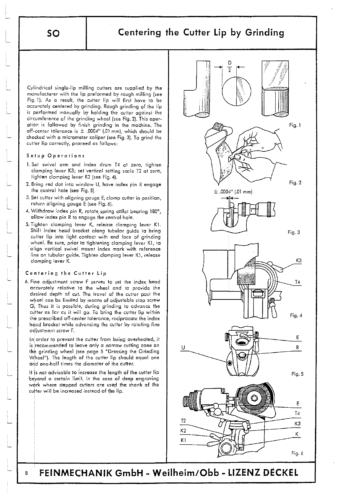
Cylindrical single-lip milling cutters are supplied by the
manufacturer with the lip preformed by rough milling (see
Fig.]). As o result, the cutter lip will first have to be
accurately centered by grinding. Rough grinding of the lip
is performed manually by holding the cutter against the
circumference of the grinding wheel (see Fig. 2). This oper-
ation is followed by finish grinding in the machine. The
off-center tolerance is ± .0004" (.01 mm), which should be
checked with a micrometer caliper (see Fig. 3). To grind the
cutter lip correctly, proceed as follows:
Setup Operations
I. Set swivel arm and index drum 14 at zero, tighten
clamping lever K3; set vertical setting scale T2 at zero,
tighten clamping lever K2 (see Fig. 4).
2.
Bring red dot into window U, have index pin R engage
the central hale (see Fig. 5).
3.
Set cutter with aligning gauge E, clamp cutter in position,
return aligning gouge E (see Fig. 6).
4.
Withdraw index pin R, rotate spring collet bearing 180,
allow index pin R to engage the central hole.
5.
Tighten clamping lever K, release clamping lever KI.
Shift index head bracket along tubular guide to bring
cutter lip into light contact with end face of grinding
wheel. Be sure, prior to tightening clomping lever Ki,- to
align vertical swivel mount index mark with reference
line on tubular guide. Tighten clamping lever K], release
clamping lever K.
Centering the Cutter Lip
6.
Fine adjustment screw F serves to set the index head
accurately relative to the wheel and to provide the
desired depth of cut. The travel of the cutter past the
wheel can be limited by means of adjustable stop screw
C. Thus it is possible, during grinding to advance the
cutter as far as it will go. To bring the cutter lip within
the prescribed off-center tolerance, reciprocate the index
head bracket while advancing the cutter by rotating fine
adjustment screw F.
In order to prevent the cutter from being overheated, it
is recommended to leave only a narrow cutting zone an
the grinding wheel (see page 5 "Dressing the Grinding
Wheel"). The length of the cutter lip should equal one
and one-half times the diameter of the cutter.
It is not advisable to increase the length of the cutter lip
beyond a certain limit. In the case of deep engraving
work where stepped cutters are used the shank of the
cutter will be increased instead of the lip.
8
FEINMECHANIK
GmbH - Weilheim/Obb
- LIZENZ DECKEL

Circular Grinding of Cutters
-
so
Grinding the Back Rake Angle of Side Cutting Edges
After centering the cutter lip it will be necessary to grind
the back rake angles of both the side cutting edge and
the end cutting edge. The back rake angles of both cutting
edges should be selected to suit the material to be cut (see
To grind the back rake angle of the side cutting edge of
cylindrical cutters (Fig. 1), proceed as follows:
Setup Operations
Fig 1
1.
Rotate swivel arm to set index drum 14 at zero; tighten
R
clamping lever K3.
2.
Bring red dot into window U; engage index pin R into
central hole.
.
no
3.
Align cutter by means of gauge E
;
grip cutter in position;
:
return gauge E, see Fig. 2.
14
4.
Release clamping lever K2; set swivel arm at desired
K3
back rake angle, using setting scale 12; tighten clomping
lever K2, see Fig. 3.
T2
5.
Tighten clamping lever K; release clamping lever Ki;
-\
shift work fixture an tubular guide to bring cutter into
C
light contact with grinding wheel-
Fig. 2
Align index mark of vertical swivel mount with reference
line on tubular guide tighten clamping lever K1 ; release
clamping lever K.
4
Back rake
Circular Grinding
angle
& Engage index pin R into right-hand hole; grind desired
-
-
>-- -
a
diameter by rotating spring collet bearing through 360
0
.
During this operation slowly rotate adjustable stop
screw 0, while continuously rotating the spring collet
..
lBOa
bearing, to advance the work fixture past the grinding
V
- --
Fig. 3a
wheel; this will produce uniform stack removal. Fine
adjustment during circular grinding is by screw F. Stop
screw G is used to establish the length of the cylindrical
r
portion which should always be slightly longer than the
-
cutting lip.
-
T2 for a
Setup Operations
K
7. Return red dot into window U; engage index pin R into
left-hand hole to enable the collet bearing to be rotated
180 between the index plate stops.
U
Grinding the Back Rake Angle
B. When grinding the back rake angle, use the fine ad-
justment screw F over the entire range of rotation of
the collet bearing (see Fig. 3a). Grinding of the back
Index mark
Ki
K2
Reference line Fig. 3
rake angle is positively controlled. The angle is required
to extend over the entire length of the cutting lip.
The vertical swivel bearing, which permits the work
0
Land
holding fixture to be swung back, enables relief angles
R
up to
400
to be produced. Relief angles over 40
0
can be
Cutting edge
obtained by additionally rotating the collet bearing in
the index head. (Only for cylindrical or tapered cutters
with straight end cutting edges or for painted cutters.)
Upon completion of grinding operations a very narrow
land must remain at the cutting edge (see Fig. 4)
Fig. 4
F
FEINMECHANIK GmbH - Wejlhejm/Obb - LffZIENZ DECKEL
9

Cg 3
1.4
Circular Grinding of Cutters
--
Grinding the Back Rake Angle of End Cutting Edges (Straight)
so
4:.
/1
'I
Nta 1 Profile
Fig. 1
The end cutting edge illustrated in Fig. 1 may be ground
in an operation immediately following the grinding of the
side cutting edge; or it may be ground independently. In
the latter case the cutter will have to be aligned by means
of gouge F and clomped in position. Whenever a single-
lip cutter is to be ground, the aligning gauge will have to
be used, as one leg of the cutting angle is formed by the
cutting lip surface. The back rake angle should be selected
to suit the material to be cut (see page 7).
Setup Operations
1.
Engage index pin R into central hale; bring red dot
into window U.
2.
Release clomping lever K2; using setting scale T2, set
swivel arm at approx. 3
0
; tighten clamping lever K2.
3.
Release clamping levers K3 and K4; hold index drum T4
against stop and, beginning at
90a.positian,
set swivel
arm at desired angle; for example set arm at 75
0
for
back rake angle of 15
0
(see Figs. 2 and 3). Tighten clomp-
ing levers K3 and K4.
4.
Tighten clamping lever K; release lever K1; shift work
Fixture an tubular guide to bring cutter into light contact
with grinding wheel. Align index mark of vertical swivel
mount with reference line an tubular guide; tighten
clamping lever K1 ; release lever K.
Grinding the Back Rake Angle
5.
Fine adjustment screw F serves to set the index head
laterally relative to the wheel and to set the work for
the desired depth of cut. - It is also possible to produce
the desired bock rake by holding the cutter against the
circumference of the grinding wheel as is shown in Fig. 4.
110
FEINMECHANIK GmbH - Weilheim/Obb - LIZENZ DECKEL

No. 2 Profile
No. 3 Profile
Fig. 1
15
Fig. S
Circular Grinding of Cutters -
so
Grinding the Back Rake Angle of End Cutting Edges (Round)
Cutter profiles having either on-center or off-center radii
are derived from cylindrical single-lip cutters having a
straight end cutting edge by rounding off the corner as
shown in Fig. 1 (No.2 and 3 profiles).
In rounded cutters of this type the bock rake angle of the
side cutting edge is the some as that of the end cutting
edge. For this reason it is necessary, during grinding the
end rake angle, that the work fixture is set at the side rake
angle by means of setting scale 12. If the end cutting edge
is ground immediately after grinding the side cutting edge,
it will not be necessary to re-set the work fixture and to
re-align the cutting lip by means of gauge E -
Setup Operations
1.
Engage index pin R into left-hand hale; bring red dot
into window U.
2.
a)No. 2 profile: Release clamping lever KS; rotate
knurled knob 55 to set crass slide by means of vernier
scale T5 for desired radius (to the right); tighten
clamping lever K5, see Fig. 2. As the radiused corner
is required to be tangent to the cutter diameter, the
amount of offset "a is:a =
Example:
Given r = .06" (1.5 mm); D = .30" (8 mm)
o = .15" (4 mm) —.06" (1.5 mm) = .09" (2.5 mm)
2. b)No. 3 profile: The vernier scale 15 of the crass slide
must be set at zero (see Fig. 3).
3.
Rotate fine adjustment screw F to bring the side cutting
edge of the cutter into light contact with the face of
the grinding wheel. Caution: Do not injure the land of
the hide cuffing edge. Now screw F must no longer be
rotated.
Grinding the Back Rake Angle
4.
Swivel index head through
90
(see Fig. 4). Depth of
cut adjustment now is by index head slide T. Fine
adjustment is by micrometer screw S6 of the index
head slide with adjustment screw D6 tightened. The
end of the cutter is rounded by slowly swivelling the
index head back to its original position, while the
collet bearing is continuously rotated bock and forth
between the stops, the rotation being through
1800
(see
Figs. 5 and 6). Friar to grinding, be sure to withdraw
the index head a slight amount by rotating screw 56
in order to prevent overheating of the cutter by exces-
sive stock removal. After each pass of the grinding
wheel the cutter is then fed towards the wheel by
means of screw 56.
In order to obtain a satisfactory cutting edge it is advis-
able, as a final operation, to swivel the index head through
90
0
with the cutter lip pointing vertically upward.
In cases where cutters given a No.3 profile are intended
for the machining of hard steel which requires a small bath
rake angle, it is good practice to flatten the curvature of
the cutter by a manual grinding operation as shown in
Fig. 7.
F8NMECHANIK GmbH - Weilheim/Obb - LIZENZ DECKEL
11

Fig. 1
g. 2
ex
F!. 40
mark
K1
Fig. 3
.0004" (.01 mm) c
r
f3
/
Reference
K2
line
3C
so
Grinding Pointed Cutters
Where pointed cutters are concerned, both the included
angle of the point and the bock rake angle are produced
in one operation (see Fig. 1). The bad, rake angle should
be selected to suit the material to be cut (see page 7).
Setup Operations
I. Engage index pin R into central hole; bring red dot into
window U.
2.
Align cutler lip by means of gouge F; grip cutter in
position
;
return gouge E.
3.
Engage index pin R into left-hand hole to enable collet
bearing to be rotated 180 between stops.
4.
Release clomping levers K3 and K4
;
hold index drum
T4 against stop and, beginning at zero position, set
swivel arm at one-half the desHed point angle (see
Fig. 2).
Example: Given o point angle of 60 . Set swivel arm by
index drum 14 at 30 . Retighten clomping levers K3
and K4.
5.
Release clomping lever K2; set work fixture for desired
bock rake angle by means of setting scale T2, see Fig. 3.
Thighten clomping lever <2.
6.
Tighten clomping lever K; release lever K1; shift work
Fixture on tubular guide to bring cutter into light contact
with grinding wheel. Align index mark of vertical swivel
mount with reference line on tubular guide; tighten
clomping lever K1
;
release lever K.
Grinding the Back Rake Angle
7.
During grinding slowly return stop screw G to advance
the work fixture post the wheel; at the some time continu-
ously rotate the collet bearing bock and forth between
the stops, the rotation being through 180'. This ensures
uniform stock removal (see Figs. 4o, b, c). Uniform stock
removal will protect the cutter from overheating.
Whet the cutter point by means of on oil stone. It is advis-
able to whet the paint as for as engraving conditions
permit. This operation will give the point a small end cut-
ting edge which will participate in removing stock (see
Fig. 5). However, where hairline engraving work is con-
cerned (depth of cut not exceeding .0004" .01 mm), the
shape of the point should not be changed; only the cutting
edge proper should be carefully whetted.
In addition it is recommended to whet also the cutting lip
by means of on oil stone in order to remove burrs. How-
ever, core should be exercised not to remove noticeable
amounts of stock from the cutting lip, as this would destroy
the centering of the lip; moreover, this would render o
greater or lesser port of it useless. When grinding the
cutting lip for the first time, core has to be token to grind
with a positive tolerance.
A
Fig. 5
FEINMECHANIK GmbH - Weilheim/Obb - LIZENZ DECKEL

L1
LI__
nfl
IF
1yi\
lit
fl/A
F
7
I
frfl
/1
2
2
No.5 Profile
Na. 6 Profile
Fig.]
Na. 7 Profile
Fig.2
Fig.3
FP
Fig. 4
I. S
10
41
Fic.
I-
Grinding Tapered Cutters -
so
A. Circular Grinding of Side and End Cutting Edges
Tapered cutters can be ground to size in the machine
without the use of any measuring instrument, exept for
the scales provided on the machine. For circular grinding
operations, on profiled cutters follow this procedure:
Setup Operations
1. Engage index pin E into central hole; bring red dot
into window U.
2. Align cutter lip by means of gouge E; grip cutter in
position; return gouge E.
3. Engage index pin R into right-hand hole to enable
collet bearing to be rotated through
3600.
Release
clomping levers K2, K3, K4. Set scale T2 and T4 at
zero Tighten clamping levers K, K2, K3, K4, see Fig. 4.
4.
Release clamping lever Ki; bring cutter diameter into
light contact with grinding wheel; tighten clomping
lever KI, taking care to keep index mark of vertical
swivel mount aligned with reference line on tubular
guide; release clomping lever K, see Fig. 4.
5. o)Na. 5 profile (Figs. I and 2): Release clomping lever
KS
;
rotate knurled knob 55 to shift cross slide to the
right by one-half of the diameter of the taper ('o in
Fig. 1); for this purpose use cross slide vernier scale
T5. Tighten clamping lever KS. -
5. b)Na,6 ptauile (Figs. I and 2): Release clamping lever
KS; rotate knurled knob 55 to shift cross slide to the
right by the desired amount 'a" (use crass slide vernier
scale T5). Tighten clomping lever K5.
5. c)Na. 7 profile (Figs. 1 and 3): Set cross slide vernier
scale at zero.
6. a)No. 5 and 7 profiles: Rotate fine adjustment screw F
to bring cutter diameter into light contact with grind-
ing wheel; Again rotate screw F to shift cutter to the
left by amount x =
—a. To facilitate this setting
operation, set scale drum of screw F at zero without
disturbing the setting of the screw (see Fig. 4).
6.
b)Na. 6 profile: Rotate screw F to bring cutter diameter
into light contact with grinding wheel
;
again rotate
screw F to shift cutter to the left by the amount
x =
—to—
,
0. To facilitate this setting operation,
set scale drum of screw F at zero without disturbing
the setting of the screw (see Fig. 4).
7.
Release clamping lever K3; rotate swivel arm through
900; release clomping lever Ko; rotate index head
slide rnicrameter screw 56 to advance end face of
cutter towards grinding wheel. Where tapered cutters
are Ia be resharpened, the length of the cutting edge
at the end of the cutter should be made greater than
the small diameter of the tapered portion.
8.
Release clamping lever K4; hold index drum 14 against
its stop and, counting from the zero position, set swivel
arm at the desired taper angle; tighten clamping
levers K3 and K4, see Fig. 5.
Circular Grinding
9.
a)Na. S profile: Slowly return stop screw 0 and con-
tinuously rotate the collet bearing through 360° to
advance the cutter past the grinding wheel. Prior to
the circular grinding operation rotate fine ad1ustment
screw F to shift the cutter to the right
;
then advance
the cutter towards the wheel by small increments
until the desired size has been obtained (see Fig. 6).
.9. b)Na. 6 and 7 profiles: Release clamping lever K3; first
slowly return stop screw 0, then slowly swing the
swivel arm while continuously rotating the collet
bearing through 360
0
to move the cutter past the
wheel and thus to circular grind bath the taper and
the radius. Prior to the circular grinding operation
rotate fine adjustment screw F to shift the cutter to
the right; then advance the cutter towards the wheel
by small increments until the desired size has been
obtained (see Figs. 7 and 8).
FEINMECHANIK GmbH - Weilheim/Obb - 1.IZENZ DECKEL
13

Fig. 3
Pi- 1
Fig. 5
so
Grinding Tapered Cutters -
(B) Grinding the Back Rake Angie of Side and End Cutting Edges (Straight)
The bock rake angles of the side and end cutting edges
may be ground immediately after circular grinding the
desired cutter profile; or in cases where only the taper
angle (not, however, the small diameter of the tapered
portion) is of importance, grinding may be performed in
an independent operation. Where the small taper diameter
must be held within close tolerances, only the end cutting
face will be ground
;
in this case the cutter will have to be
aligned by means of gauge E and clamped in position. The
back rake angles of the side and end cutting edges should
be selected to suit the material to be cut (see page 7). For
tool angles refer to Fig. 1.
Grinding the Side Cutting Edge
Setup Operations
1.
Engage index pin R into left-hand hale; bring red dot
into window U.
2.
Release clamping lever K2; using scale T2, set cutter at
desired back rake angle
;
tighten clomping lever K2, see
Fig. 2.
3.
Tighten clamping lever K; "release lever Ki
;
shift work
fixture on tubular guide to bring cutter into light contact
with grinding wheel; tightenclomping lever Ki, taking
care to keep index mark of vertical swivel mount aligned
with reference line on tubular guide; release clamping
lever K.
Grinding the Bock Rake Angie
4.
While continuously rotating the collet bearing through
1600 (bock and forth between the stops), advance the
cutter towards the grinding wheel by means of fine
adjustment screw F. This will produce the desired bock
rake angle in a positively controlled operation (see
Fig. 2).
Upon completion of the grinding operations on the side
cutting edge, a very narrow land must remain at the
edge.
Grinding the End Cutting Edge
Setup Operations
1.
Engage index pin R into central hale
;
bring red dot into
window U.
2.
Release clomping lever K2; using scale T2, set swivel
arm at an angle of approx. 30; tighten clamping lever
K2, see Fig. 3.
3.
Release clomping levers K3 and K4; hold scale T4 against
its stop and, beginning
of
the 90
0
-positian, set swivel
arm at the desired angle; for example, where an angle
of
100
is desired, the swivel arm will have to be set at
80
0
. Tighten clamping levers K3 and K4, see Fig. 4.
4.
Tighten clamping lever K; release lever KI; shift work
fixture along tubular guide to bring end face of cutter
into light contact with grinding wheel; tighten clamping
lever K1, taking care to keep index mark of vertical
swivel mount aligned with reference line on tubular
guide; release clamping lever K.
Grinding the Back Rake Angle
5.
Lateralfine adjustment of the work Fixture relative to
the grinding wheel and adjustment for depth of cut is
obtained by means of screw i
-
. iris aisa passible to grind
the back rake angle manually; care should, however, be
taken to produce the correct tool angles (see Fig. 5).
In cases where close tolerances an the small taper diam-
eter after grinding the end cuffing edge are prescribed,
the corner of the side cuffing edge will have to be main-
tained; this will make it possible to check whether or not
the small taper diameter was changed during grinding
operations (see Fig. 6).
c
I
1
14
FEINMECHANIK GmbH — Weilheim/Qbb — LIZENZ DECKEL

Grinding Tapered Cutters -
so
C. Grinding the Back Rake Angle of Side and End Cutting Edges (Round)
Tapered cutters having either an off-center or an on-center
radius can be given a back rake angle only in connection
with the circular grinding operation (see Fig. 1). The back
rake angle of the side cutting edge equals that of the
straight or rounded end cutting edge: the proper angle to
be used will be found in page 7. After tapered cutters
with rounded end cutting edges have become dull, first
proceed with the circular grinding operation described an
page 13; then fallow the procedure indicated below.
Setup Operations
1.
Engage index pin R into left-hand hole; bring red dot
into window U.
2.
Release clamping lever K2; use scale T2 to set work
Fixture at desired bock rake angle
;
tighten clamping
lever 1(2.
3.
Tighten clomping lever K; release lever K1 ; shift work
Fixture along tubular guide to bring cutter into light
contact with grinding wheel; tighten clomping lever K1
taking core to keep index mark of vertical swivel mount
aligned with reference line on tubular guide; release
clamping lever K, see Fig. 2.
Grinding the Back Rake Angle
4.
While continuously rotating the collet bearing through
180 (bock and forth between the stops), advance the
cutter towards the grinding wheel by means of Fine
adjustment screw F. This will produce the desired bock
rake angle on both the side and the end cutting edges
in o positively controlled operation (see Figs. 3, 4, 5).
Upon completion of grinding operations, o very narrow
land must remain at the cutting edge.
5.
In cases where the cutter is intended for the machining
of hard steel which requires a small bock rake angle, it
is advisable to grind off port of the curvature in o
manual operation (see Fig. 6).
In addition it is recommended, with regard to all single-lip
cutters, to whet also the cutting lip by means of on oil
stone in order to remove burrs. However, core should be
exercised not to remove noticeable amounts of stock from
the cutting lip, as this would destroy the centering of the
lip; moreover, this would render a greater or lesser port
of it useless.
No.6 Profile
No.7 Profile
F;,-, I
- I
F8NMECHANIK GmbH - Weilheim/Obb - LIZENZ DECKEL
15

Accessories
so
Changing the Drive Cord and Grinding Wheel
4
3
2
1
To change the drive cord, proceed as follows:
1.
Bock off and remove hexagon nut;
2.
pull
off
grinding wheel;
3.
loosen hexagon socket screws and take off wheel guard;
4.
replpce drive cord.
To re-assemble the parts, reverse the above procedure.
For tensioning the cord, adjust the motor bracket (bock off hexagon socket screws).
The grinding wheel is attached to the grinding spindle by means
of
a wheel mount. The entire assembly, i.e.,
wheel and mount, is puThed on the spindle and secured by hexagon nut 1.
5light out-of-round of the grinding wheel may be adjusted by backing off the nut on the wheel mount.
16
FEINMECHANIK GmbH - Weilheim/Obb - LIZENZ DECKEL

Pedestal
Installing the Machine Lamp
so
The welded all-steel pedestal, designed to eliminate vibra-
tion, permits the grinder to be placed at any point of the
workshop. All controls are at a level most convenient for
the operator, and the machine is independent of work
benches or wall brackets. The diagram an the right shows
the position in which the grinder should be secured to the
pedestal by means of two bolts inserted from above.
The pedestal comprises a bandy tray for tools and the
like and has a hinged accessory box.
Overall height of pedestal:
3872
in
(980
mm)
Dimensions of pedestal base: 17'14:< 1 1 Vt in.
(450x300
mm)
Approx. weight:
79
lb
(35
kg)
.6 (15 mm)
Installing the Machine Lamp
Slide the tubular lamp holder into the vertical bore provided in the upper portion of the machine and push
down until the retaining screw engages the slot in the tubular holder. Then insert the thrust plate and compres-
sion spring and tighten the clomping screw (Fig. 2). Thread the cable through the hole in the machine base
and connect to lighting circuit (Fig. 1).
fl
Clomping scre
Compression sj
Thrust plate
Retaining scre
2
FEINMECHANIK GmbH - Weilheim/Qbb - LIZENZ DECKEL
17

Special Index Head
Locating Fixture for Cutter Spindle Assembly
A special index head is available for receiving cylindrical-shank cutters of " or 1" diameter or M.T. 1, ML 2,
or M.T. 3 taper shankcutters.
Except for cylindrical-shank cutters of I" diameter, which are mounted direct in the index head, a clamping
sleeve or taper sleeve (5), respectively, is interposed for locating the cutters. The head is provided with 2
hexagon socket screws at the front and 2 at the rear (i) for clamping the cutters as required.
The locating fixture for the spindle assembly permits
regrinding of single-lip cutters while held in the
Locatinp
cutter spindle of the milling machine. For this pur-
fixture
pose, remove the index head slide from its bracket
assembly
after loosening screw Do and clamp Ko and insert
the locating fixture into the V-guide of the index
Do head bracket. For grinding operations insert the
spindle assembly with cutter into the locating fixture
and clamp firmly. The index pin engages the notches
provided on the card pulley of the spindle assembly.
Exchanging the index heads may cause on eccentricity which should be determined as follows: -
Set the scale of the cross slide at zero, mount an qrbor"o on the standard index head and bring the arbor
into light contact with the grinding wheel.
-
Now exchange index heads and, depending on the type of sleeve used, mount on arbor "A" on the special
index head. (The some procedure applies if the locating fixture for the cutter spindle assembly ii mounted
instead of the standard index head.)
Again adjust the cross slide until arbor "A" is in light contact with the grinding wheel.
The value which is read above or below dimension "X (see formula below) on the scale of the cross slide is
the desired amount of eccentricity. It must be taken into account for all settings mod"e with the special index
head or the locating fixture.
A-a
Dimension X =
.
18
FEINMECHANIK GmbH Weilheirn/Obb - LIZENZ DECKEL
I
'V
Table of contents
Popular Grinder manuals by other brands

DeWalt
DeWalt DCG413 instruction manual

Parkside
Parkside PFBS 9.6 A1 Operation and safety notes

Bosch
Bosch GWS Professional 7-100 GWS Professional Original instructions

La Pavoni
La Pavoni PA-8801B user manual

Extol Industrial
Extol Industrial SHARE 8791840 Translation of the original user manual

Hilti
Hilti AG 6D-22-125 manual