ARO GH03A Series User manual

ARO.
OPERATOR’S MANUAL
INCLUDING:OPERATION,INSTALLATION& MAINTENANCE MANUAL 150
F
Part No.
Revised: 49999-217 E
01-16-98
P
SERIES GH03A AND GHX03A GRINDERS
Series GH03A and GHX03A Grinders are designed for close-quarter work in the metal fabricating
industry, shipyards, pipe fabrication, die and mold manufacturing and limited space applications.
They are particularly good where conduits, pipes, ducts etc. pass through bulkheads or frames.
These small Grinders are very efficient at grinding weld bead and leaving a fine finish.
ARO is not responsible for customer modification of tools for applications on which ARO was not
consulted.
IMPORTANT SAFETY INFORMATION ENCLOSED.
READ THIS MANUAL BEFORE OPERATING TOOL.
IT IS THE RESPONSIBILITY OF THE EMPLOYER TO PLACE THE INFORMATION
IN THIS MANUAL INTO THE HANDS OF THE OPERATOR.
FAILURE TO OBSERVE THE FOLLOWING WARNINGS COULD RESULT IN INJURY.
PLACING TOOL IN SERVICE
.
Always operate, inspect and maintain this tool in
accordance with American National Standards
Institute Safety Code for Portable Air Tools
(ANSI B186.1).
. For safety, top performance, and maximum durability
of parts, operate this tool at 90 psig (6.2 bar/620 kPa)
maximum air pressure at the inlet with 5/16” (8 mm)
inside diameter air supply hose.
. Always turn off the air supply and disconnect the air
supply hose before installing, removing or adjusting
any accessory on this tool, or before performing any
maintenance on this tool.
. Do not use damaged, frayed or deteriorated air hoses
and fittings.
. Be sure all hoses and fittings are the correct size and
are tightly secured. See Dwg. TPD905-1 for a typical
piping arrangement.
l
Always use clean, dry air at 90 psig maximum air
pressure. Dust, corrosive fumes and/or excessive
moisture can ruin the motor of an air tool.
. Do not lubricate tools with flammable or volatile liq-
uids such as kerosene, diesel or jet fuel.
. Do not remove any labels. Replace any damaged label.
USING THE TOOL
.
.
.
.
.
.
.
.
.
.
Always wear eye protection when operating or
performing maintenance on this tool.
Always wear hearing protection when operating this
tool.
Keep hands, loose clothing and long hair away from
rotating end of tool.
Anticipate and be alert for sudden changes in motion
during start up and operation of any power tool.
Keep body stance balanced and firm. Do not over-
reach when operating this tool. High reaction torques
can occur at or below the recommended air pressure.
Tool accessories may continue to rotate briefly after
throttle is released.
Air powered tools can vibrate in use. Vibration, re-
petitive motions or uncomfortable positions may be
harmful to your hands and arms. Stop using any tool
if discomfort, tingling feeling or pain occurs. Seek
medical advice before resuming use.
Use accessories recommended by ARO.
This tool is not designed for working in explosive
atmospheres.
This tool is not insulated against electric shock.
The use of other than genuine ARO replacement parts may result in safety hazards, decreased tool performance, and
increased maintenance, and may invalidate all warranties.
Repairs should be made only by authorized trained personnel. Consult your nearest ARO Tool Products Authorized
Servicenter.
For parts and service information, contact your local ARO distributor, or the Customer Service Dept. of the Ingersoll-Rand
Distribution Center, White House, TN at PH: (615) 672-0321, FAX: (615) 672-0601.
ARO Tool Products
Ingersoll-Rand Company
ARO.
1725 U.S. No. 1 North
l
P.O. Box 8000
l
Southern Pines, NC 28388-8000
©1997 INGERSOLL-RAND COMPANY • PRINTED IN U.S.A.

WARNING LABEL IDENTIFICATION
FAILURE TO OBSERVE THE FOLLOWING WARNINGS COULD RESULT IN INJURY.
WARNING
I
WARNING
GRINDER SPECIFIC WARNINGS
Do not use this tool if actual free speed exceeds the
nameplate rpm.
Before mounting a wheel, after any tool repair or
whenever a Grinder is issued for use, check free
speed of Grinder with a tachometer to make certain
its actual speed at 90 psig (6.2 bar/620 kPa) does not
exceed rpm stamped or printed on the nameplate.
Grinders in use on the job must be similarly
checked at least once each shift.
Always use the recommended ARO Wheel Guard
furnished with the Grinder.
Do not use any grinding wheel, bur or other
accessory having a maximum operating speed less
than the free speed of the Grinder in which it is
being used. Always conform to maximum rpm on
grinding wheel blotters.
Inspect all grinding wheels for chips or cracks prior to
mounting. Do not use a wheel that is chipped or
cracked or otherwise damaged. Do not use a wheel
that has been soaked in water or any other liquid.
Make certain grinding wheel properly fits the
arbor. Do not use reducing bushings to adapt a
wheel to any arbor unless such bushings are
supplied by and recommended by the wheel
manufacturer.
After mounting a new wheel, hold the Grinder
under a steel workbench or inside a casting and run it
for at least 60 seconds. Make certain no one is
within the operating plane of the grinding wheel. If
a wheel is defective, improperly mounted or the
wrong size and speed, this is the time it will usually
fail.
150
WARNING
When starting with a cold wheel, apply it to the
work slowly until the wheel gradually warms up.
Make smooth contact with the work and avoid
any bumping action or excessive pressure.
Always replace a damaged, bent or severely worn
wheel guard. Do not use a wheel guard that has
been subjected to a wheel failure.
Make certain wheel flanges are at least 1/3 the
diameter of grinding wheel, free of nicks, burrs and
sharp edges. Always use wheel flanges furnished by
the manufacturer; never use a makeshift flange or a
plain washer. Tighten Flange Nut securely.
Guard opening must face away from operator.
Bottom of wheel must not project beyond guard.
Always match collet size with accessory shank size.
Always insert tool shank no less than 10 mm in the
collet. Tighten Collet Nut securely to prevent
accessory from working out during operation of the
Grinder. Check tightness of Collet Nut before
operating the Grinder. Pay particular attention to
the fact that allowed speed of a mounted point is
lowered when the length of the shaft is increased
between end of collet and mounted point (overhang).
2

PLACING TOOL IN SERVICE 150
WARNING:
Incorrect combinations of grinding wheel, wheel guard and tool speed could result in injury.
Correct combinations are specified below:
Guard Part Number Wheel Type
AG20-106-3 27
Wheel Diameter
in. (mm)
3 (76)
Maximum Wheel
Thickness
in. (mm)
1/4 (6.4)
Maximum Speed
rpm
26 250
LUBRICATION
IRAX No. 1OP
IRAX No. 5OP IRAX No. 68 1LB
Always usean air line lubricator with thesetools.
We recommend the following Filter-Lubricator-Regulator
unit:
For USA - IRAX No. Cll-03400
After each two hours of operation,
if an air line lubricator is
not used,inject l/2 to 1cc of IRAX No. 10POil into the Air
Inlet.
MAIN LINES
3
TIMES
AIR TOOL INLET SIZE
BRANCH LINE 2
AIR TOOL INLET SIZE
DRAIN REGULARLY COMPRESSOR
HOW TO ORDER ELITE GRINDERS
(Dwg. TPD905-1)
GRINDERS with 3/8" -24 thread ARBOR
Model
GH03A-20RG-3 (Rear Exhaust)
Speed/rpm
20 ooo
GRINDERS with 1/4” COLLET
GH03A-35RC-2 (Rear Exhaust)
GH03A-30RC-2 (Rear Exhaust)
GH03A-25RC-2 (Rear Exhaust) 30 000
I 25 000
GH03A-20RC-2 (Rear Exhaust) I 20 ooo
3” EXTENDED GRINDERS with 1/4” COLLET
GHX03A-30RC-2 (Rear Exhaust) I 30000
GHX03A-25RC-2 (Rear Exhaust) I 25 000
GRINDERS with 6 mm COLLET
GH03A-20RC-6M (Rear Exhaust) I 20 ooo
GH03A-30RC-6M (Rear Exhaust) 30 000
GH03A-35RC-6M (Rear Exhaust) 35 ooo
3” EXT. GRINDERS with 8 mm COLLET
GHX03A-30RC-6M (Rear Exhaust) I 30 000
3

150
PLACING TOOL IN SERVICE
The following equipment is available at an extra price and
must be ordered separately:
1. Piped-Away Exhaust Kit Part No. LGl-K284
2. Variable Speed Control Part No. LGl-A1015
3. Throttle Valve Kit Part No. LGl-K300
To order a front exhaust tool from the factory,
substitute the letter “F” for the letter “R” in the above
models. Example: GH03A-25RC-2 Rear Exhaust
Model becomes GH03A-25FC-2 Front Exhaust Model.
With the exception of models having Low-Profile
Concentric Flanges, all other models listed above can be
changed to front exhaust tools by reversing the Flow
Ring and aligning the indicator marks with the letter
“F” on the Housing.
HOW TO ORDER CUSTOM MODELS
1. To order a tool with a Locking Lever, select the desired 3. To order a tool with piped away exhaust, select the
model and add an “L” to the end of the existing
number. desired model and add a “-P” to the end of the existing
number.
Example: GH03A-25RC-2-L Example: GH03A-35RC-2-P
Anytime a tool is ordered with a Low-Profile
Concentric Flange, it will come equipped with a
Locking Lever from the factory.
To order a combination of options, add the required
letters to the end of the model number in the
following order: L or C, P, D
2. To order a tool with a Low-Profile Concentric Flange,
Example: GH03A-35RC-4-LP or
select the desired model and add a -“C” to the end of
GH03A-35RC-4-CPD
the existing number.
Example: GH03A-35RC-2-C
4

150
NEW GRINDER TO ACCESSORY COLOR MATCHING GUIDE
Ingersoll-Rand Tool & Hoist Division has pioneered a new
color code system designed to:
1. Simplify the identification of rated tool speed via a
unique corresponding color match.
2. Easily communicate the appropriate backing pads and
accessories for each tool through a matching color
code system on the backing pads and/or other
corresponding Grinder accessories.
3. The chart below demonstrates the color code system
between the Grinder and the accessory.
SPEED COLOR
NAMEPLATE
RED
ORANGE
YELLOW
GREEN
BLUE
GREY
TAN
VIOLET
(READ FROM LEFT TO RIGHT)
RATED
SAFE RANGE ACCESSORY [MAXIMUM OPERATING SPEED)
(Dwg. TPD1146-1)
5

ARO-
MANUEL DE L’OPERATEUR
I-1998
COMPRENANT : EXPLOlTATION, INSTALLATION & ENTRETIEN
0
F
MEULEUSES DES SERIES GH03A ET GHX03A
Les meuleuses des Series GHOBA et GHX03A sont destinies aux travaux dans des endroits restreints
dans I’industrie des fabrications metalliques, des chantiers navals, des fabrications de tuyauteries, de
matrices et de moules, et pour toutes les applications ou I’espace est limit& En particulier, elks sont
idhales dans les endroits ou les tubes, tuyauteries, gaines, etc. passent ir travers des cloisons ou des
chksis. Ces petites meuleuses sont trks efficaces pour le meulage des cordons de soudure lorsqu’une
bonne finition est requise.
ARO ne peut Qre tenu responsable de la modification des outils par le client pour les adapter h des ap-
plications qui n’ont pas et6 approuvees par ARO.
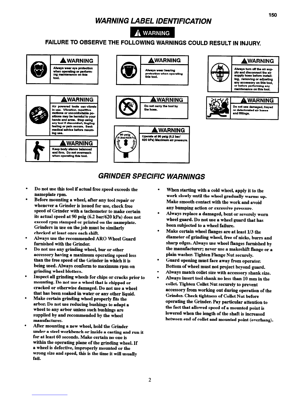
D’IMPORTANTES INFORMATIONS DE SEClJRITk SONT JOINTES.
LIRE CE MANUEL AVANT D’UTILISER L’OUTIL.
L’EMPLOYEUR EST TENU A COMMUNIQUER LES INFORMATIONS
DE CE MANUEL AUX EMPLOYkS UTILISANT CET OUTIL.
LE NON RESPECT DES AVERTISSEMENTS SUIVANTS PEUT CAUSER DES BLESSURES.
MISE EN SERVICE DE L’OUTIL
Porter toyjours une protection acoustique pendant
l’utilisation de cet outil.
Tolljotus exploiter, inspecter et entretenh- cet outil
conformCment au Code de securite des outils pneuma-
tiques portatifs de 1’American National Standards
Institute (ANSI B186.1).
Couper to4jours l’alhuentation d’air comprhue et
debrancher le flexible d’alhnentation avant d’instal-
ler, deposer ou ajuster tout accessoire sur cet outil, ou
d’entreprendre une operation d’entretien quelconque
sur l’outil.
Ne pas utiliser des flexibles ou des raccords endom-
mages, effiloches ou dit&ior&.
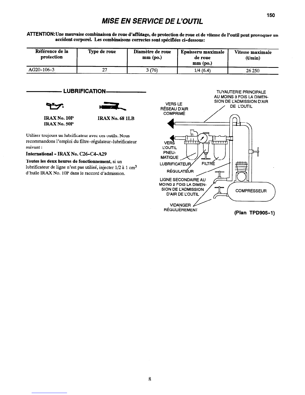
S’assurer que tous les flexibles et les raccords sont
correctement dhuensionnQ et bien set-r&. Voir Plan
TPD905-1 pour un exemple type d’agencement des
tuyauteries.
Utiliser toujours de Pair set et propre P une pression
maxhnum de 6,2 bar. La poussi&e, les fumees corro-
sives et/au une humidit excessive peuvent endom-
mager le moteur d’un outil pneumatique.
Ne jamais lubriller les outils avec des liquides inllam-
mables ou volatiles tels que le k&osene, le gasol ou le
carburant d’aviation.
Ne retirer aucune etiquette. Remplacer toute etiquette
endommagie.
UTILISATION DE L’OUTIL
.
Porter to~ours des lunettes de protection pendant
l’utilisation et l’entretien de cet outll.
Tenir les mains, les v&ements llous et les cheveux
longs, 6loignes de l’extr&ni~ rotative de l’outil.
Pr&oir, et ne pas oublier, que tout 011thmotoris est
susceptible d’8-coups brusques lots de sa mise en
marche et pendant son utilisation.
Carder une position equilibr4e et ferme. Ne pas se
pencher trop en avant pendant l’utilisation de cet out-
il. Des couples de reaction Clevis peuvent se produire
A, ou en dessous, de la pression d’air recommandie.
La rotation des accessoires de l’outil peut continuer
pendant un certain temps aptis le rel&hement de la
gtchette.
Les outils pneumatiques peuvent vibrer pendant l’ex-
ploitation. Les vibrations, les mouvements repetitifs et
les positions hrconfortables peuvent causer des dou-
leurs darts les mains et les bras. N’utiliser plus d’outils
en cas d’inconfort, de picotements ou de douleurs.
Consulter un mCdecht avant de recommencer P utilis-
er l’outil.
Utillser les accessoires recommend& par ARO.
Cet outll n’est pas con9u pour fonctionner darts des
atmospheres explosives,
Cet outil n’est pas is016 contre les chocs ilectriques.
LWilisation de rechanges autres que les pieces d’origineAR0 peut causer des risques d’in&curiti, tiduire les performances de
Poutil et augmenter l’entretien, et peut annuler toutes les garanties.
Les reparations ne doivent &-e effectuees que par des reparateurs qualifies autoris6. Consultez votre Centre de Service ARO
Tool Products le plus proche.
Pour les informations relatives aux pikes et au service, contacter votre distributeur ARO.
ARO Tool Products
Ingersoll-Rand Company
1725 U.S. No. I North, PO Box 8000, Southern Pines, NC 28388-8000
01998 INGERSOLL-RAND COMPANY Imprime aux E.U.
ARO-

SIGNIFICATION DES ETIQUE7TES D’AVERTISSEMENT 150
LE NON RESPECT DES AVERTISSEMENTS SUIVANTS PEUT C
I 1
A ATTENTION
Los outlb prwumtlgma
p.uv*nt Vlbrw pond9nt
I’mxpl-. Lee VlbmtkM,
I.* -mm~ +6tltlb ot I.0
pomltkmm Irnonfolhbb8
pwvml lxu8.r de* doulmm
daru b* rnh .i lea bma.
N’utllbw plus d’oullh .n c..
d’lnconfoft da pk*nwnh 0”
do doukun. Consulkr un
m&deck wwd da neomnwm.r
i UtllkW I’outll.
IA
AlTENTlON 1
(iifi;G~~%c.t1
USER DES BLESSURES
A ATTENTION
Cwpr tollloun I’~llmnt9tkn
d’alr comprlmi aI d6bmmh.r k
fkxlbk d’allm- avant
d’lntilkr. d6pa.r ou ajwter
tout acc.moln .“I cot wtll, ou
d’atmpnndm una ophtlon
d’wdmtkn qwkonqw au, I’ou-
111.
I
00P&l
(G+am?okP~
10
zs f
/ Q
uulk*r da IWr comprlmi
i ma prosdom maxhum
da 62 bar (620 kP@.
AVERTISSEMENTS SPECIFIQUES AlJX MEULEUSES
Ne pas utiliser cet outil si la vitesse B vide r4elle
depasse celle indiquee sur la plaque signalktique.
Avant de monter une meule, apr&s toute reparation de
l’outil ou avant de four& une meuleuse pour
utilisation, v&Rer la vitesse $ vide de la meuleuse
avec un tachym&re pour s’assurer que la vitesse n5elle
B 6,2 bar (620 hPa) ne dCpasse pas celle pohrcomke ou
imprinke sur la plaque signal&ique. Les meuleuses
sorties sur chantier doivent &re v&i!Xes de la mime
facon au mohrs une fois par poste.
Utiliser tolljours le protige-mettle ARO fourni avec la
meuleuse.
Ne jamais utiliser une meule, une fraise ou tout autre
accessoire ayant une vitesse de service hrfkieure B la
vitesse $ vide de la meuleuse sur laquelle il est month.
Respecter toujours la vitesse maxhnum htscrite sur les
disques en papier de ht mettle.
Inspecter tomes les mettles avant de les monter pour
v&ifier qu’elles ne pr&entent pas d’eclats ou de
fusures. Ne jamais utiliser une mettle Ccaillee, fusut+e
ou ayant un endommagement quelconque. Ne jamais
utiliser une meule qui a Cti trempee dens l’eau ou tout
autre liquide.
S’assurer que la mettle se monte correctement sur
l’arbre. Ne pas utiliser de bagues rGductrices, $ mohw
que ces bagues soient recommandks et fournies par le
fabricant de la meule.
AprGs avok month une nouvelle mettle, teti le
meuleuse sous un Ctabli en acier ou dans une pi&e
cot&e et la faire tourner pendant au mohrs 60
secondes. S’assurer que personne ne se tient dens le
plan de rotation de la mettle. Toute mettle dbfectueuse,
ma1 montie ou de dimension et vitesse incorrectes se
cassera generalement P ce moment hi.
Pour commencer le travail avec une mettle froide,
l’appfiquer lentement contre la piece jusqu’8 ce que la
mettle s’echauffe progressivement. Mettre la meule en
contact avec la piece en douceur en &itant tout choc
ou pression excessive.
Remplacer tolljours un protege-mettle endommage,
tordu ou h&s usi. Ne pas utiliser un protege-meule qui
a 4th soumis h la rupture d’une meule.
S’assurer que les flasques de meule couvrent au mains
l/3 du diam&re de la meule, et qu’ils sont exempts
d’entailles, de bavures et d’ar&es vives. Utiliser
tolljours les flasques fournis par le fabricant; ne
jamais utiliser de tlasque de provenance douteuse ou
de rondelle plate. Serrer fermement 1’Ccrou du
Rasque.
L’ouverture du protige-meule doit &re orientie c8te
opposC P l’ophrateur. Le bas de la mettle ne doit pas
depasser le protege-meule.
Toujours choisir une pince adaptee P la dimension de
la queue de l’accessoire.
La queue de l’outil doit toqjours ttre insCtGe dans la
phrce sur au mohrs 10 mm. Serrer fermement l’&u-ou
de pince pour Cviter tout desserrage de l’accessohe
pendant l’emploi de la meuleuse. VCrifier le serrage de
l’brou de pince avant de mettre la meuleuse en
marche. Ne jamais oublier que la vi&se admissible
d’une meule sur tige doit 6tre r6duite lorsque la
longueur de la tige entre le bout de la pince et la meule
(Porte&faux) est augmentee.
7

150
MISE EN SERVICE DE L’OUTIL
ATTENTION:Une mauvaise combhkson de ruue d’afffitage, de protection de roue et de vitesse de l’outil peut provoquer ULL
accident corporel. Les combinaisons correctes sont sp&flkes ci-dessous:
Rkfkrence de la
protection
AG20- 106-3
‘Ijpe de roue
27
DiamStre de roue
mm (PO.)
3 (76)
Epaisseru maxlmale
de roue
mm (PO.)
If4 (6.4)
Vitesse maximale
(Urnin)
26 250
LUBRIFICATION
IRAX No. 1OP
IRAX No. 5OP IRAX No. 68 1LB
Utiliser toujours un lubrificateur avec cesoutils. Nous
recommandonsl’emploi du filtre-r&ulateur-lubrificateur
suivant :
International - IRAX No. C26-C4-A29
Toutes les deux heures de fonctionnement,
si un
lubrificateur deligne n’est pasutilis6, injecter l/2 g 1cm3
d’huile IRAX No. 1OPdansle raccord d’admission.
VERS LE
R&AU D’AIR
COMPRIMk
TUYAUTERIE PRINCIPALE
AU MOINS
3
FOIS LA DIMEN-
SION DE CADMISSION D’AIR
DE COUTIL
/-
MOINS 2 FOIS IA DI
SION DE CADMISS
D’AIR DE COUTI COMPRESSEUR
VIDANGER
RiiGUUliREMENT
(Plan TPD905-11
8

ARO.
GlJiA DEL OPERARIO
1-1998
h’lANW0,
INSTALAClON Y MANlENlMlENTO
0
E
AMOLADORAS MODELOS GH03A Y GHX03A
m
Las Amoladoras Serle GHOBA y GHXOBA e&n dlseiiadas pare trabajo de cercania en la lndustrla de
fabrlcaclon de metales, astllleros, fabrlcaclon de tuberias, fabrlcaclon de moldes y troqueles y apllca-
clones en espaclos reducldos. Resultan especlalmente eficaces para aquellas sltuaciones en las que
10s conductos, tuberias, etc. atraviesan tabiques o bastidores. Estas pequeiias amoladoras son muy
eficaces para rectificar cordones de soldadura y dejar un acabado fino.
ARO no aceptara responsabllfdad alguna por la modlficacion de las herramientas efectuada por el
cllente para las aplicaciones que no havan sido consultadas con ARO.
SE ADJUNTA INFORMACldN IMPORTANTE DE SEGURIDAD.
LEA
ESTE MANUAL ANTES DE USAR LA HERRAMIENTA.
ES RESPPNSABILIDAD DE LA EMPRESA ASEGURARSE DE WE EL OPERARIO
ESTE AL TANTO DE LA INFORMACICN WE CONTIENE ESTE MANUAL.
EL
HACER CASO OMISO DE LOS AVISOS SIGUIENTES PODRiA OCASIONAR LESIONES.
PARA PONER LA HERRAMIENTA EN
SERVICIO
.
Utilice, examine y mantenga siempre esta herramien-
ta conforme al c6digo de seguridad para herramientas
neumaticas portkiles de la American National Stan-
dards Institute (ANSI B186.1).
. Corte siempre el suministro de aire y desconecte la
manguera de suministro de aire antes de instalar, des-
montar o ajustar cualquier accesorio de esta herra-
mien@ o antes de realizer cualquier operaci6n de
mantenimiento de la n&ma.
. No utilice mangueras de aire y accesorios daiiados,
desgastados ni deteriorados.
. Aseglirese de que todas las mangueras y accesorios
Sean de1 tameno correct0 y estkn bien apretados. Vea
Esq. TPD905-1 pare un tipico arreglo de tuberias.
. Use siempre aire limpio y seco a una presi6n mtixima
de 90 bar. El polvo, 10sgases corrosives y/o el exceso
de humedad podrian estropear el motor de una herra-
mienta neumfitica.
. No lubrique las herramientas con liquidos inllamables
o volsitiles tales coma queroseno, gasoil o combustible
para motores a reacciijn.
. No saque ninguna etiqueta. Sustituya toda etiqueta
daiiada.
US0 DE LA HERRAMIENTA
.
Use siempre protecci6n ocular cuando maneje, o
realice operaciones de mantenimiento en esta herra-
mienta.
Use siempre protecci6n pare 10soidos cuando maneje
esta herramienta.
Mantenga las manos, la ropa suelta y el cabello largo
alejados de1 extremo giratorio de la herramienta.
Anticipe y esti alerta sobre 10scambios repentinos en
el movimiento durante la puesta en marcha y el man-
ejo de toda herramienta motorizada.
Mantenga una postura de cuerpo equilibrada y file.
No estire demasiado 10sbrazos al manejar la herra-
mienta. Pueden ocurrir reacciones de alto par a, o a
menos de, la recomendada presidn de aire.
Los accesorios de la herramienta podrian seguir gi-
rando brevemente despub de haber soltado la palan-
ca de estrangulaci6n.
Las herramientas neumsiticas pueden vibrar durante
el uso. La vibrac%n, repetici6n o posiciones inc6mo-
das pueden daiiarle 10s brazos y manos. En case de
incomodidad, sensaci6n de hormigueo o dolor, deje de
usar la herramienta. Consulte a un medico antes de
volver a usarla otra vez.
Utilice Gnicamente 10saccesorios ARO recomendados.
Esta herramienta no ha sido diseiiada para trabajar
en ambientes explosivos.
Esta herramienta no esti aislada contra descargas
eliktricas.
El uso de piezas de recambio que no Sean las autenticas piezas ARO Tool podria poner en peligro la seguridad, reducir el rendi-
miento de la herramienta y aumentar 10scuidados de mantenhniento necesarios, asi coma invalidar toda garantia.
Las reparaciones ~610serein realizadas por personal cualillcado y autorizado. Consulte con el centro de servicio ARO Tool
Product autorizado msis pr6ximo.
Pour les informations relatives aux pikes et au service, contactez votre diitributeur ARO.
ARO Tool Products
ARO.
Ingersoll-Rand Company
1725 US. No. 1 North, PO Box 8000, Southern Pines, NC 28388-8000
@1998 INGERSOLL-RAND COMPANY lmpreso en EE.UU.

ETIQUETAS DE AVIS0
150
EL HACER CASO OMISO DE LOS AVISOS SIGUIENTES PODRiA OCASIONAR LESIONES.
Lu h.mn6.ntu n.u*a
pwdm vlbnr dunn@ ml wo.
La VlbNCh, ks movl~ntw
npftlll~om o Ima pfmkknw
I- podlim duidm km
bmza y lu mnoa. En c..o
hormIgu.a o d&r, dejmr da
““I lm hwmmhn& Co~ulhr
al midlco ant.8 da vohmr a utl-
IkNh.
Mmejar la hwrmmhnh . “IN
pm*lhl da l u mixlrn da w
palo (6,2 bar/620 kP@.
AVISOS ESPECiFlCOS DE AMOLADORA
No use esta herramienta si la velocidad libre real
excede la indicada en ht placa de identillcacMn.
Antes de montar una muele, y despues de todas las
reparaciones de herramienta y siempre que se
proporcione una Amohtdora para su uso, compruebe
Irr velocidad libre de dicha Amoladora con un
tacdmetro para asegurarse que su velocidad real a
90 psig (620 bar/6,2 kPa) no exceda las rpm
estampadas o impresas en la placa de identillcaci6n.
Las Amoladoras usadas en trabajos debetin ser
examinadas similarmente coma minhno una vez en
cada jornada de trabajo.
Use siempre el Cubremuela ARO recomendado y
suministrado con la Amoladora.
No use nunca una muela, taladro rotatorio dental o
cualquier otro accesorio que tenga una velocidad
maxima de funcionamiento menor que la velocidad
libre de la Amoladora en la que se esti usando.
Cumpla siempre las rpm mriximas indicadas en 10s
distanciadores de la muela.
Inspeccione todas las muelas antes de su mon@je para
ver si tienen grietas o roturas. No use una muela que
esti rota o agrietada o dauada de cualquier otra
forma. No use una muela que haya estado a remojo en
agua o en cualquier otro liquido.
Asegtirese de que la muela esti bien puesta en la
espiga. No use anillos reductores para adaptar una
muela a la espiga a menos que estos hayan sido
suministrados y recomendados por el fabricante de
muelas.
DespuCs de haber montado una muela nueva, sujete la
Amoladora bajo un banco de acero o en un molde y
hrigala funcionar durante 60 segundos coma minimo.
Asegikese que no haya nadie en el entorno de
operaci6n de muela. Si la muela es defectuosa, esti
ma1 montada o es de1 tamafio y velocidad incorrectas,
normalmente fallarri en este momento.
A ADVERTENCIA
Coliw 8hmpn *I l umlnl~
k &u y d.mxm.ct,r * mn-
glmn da l nMhtm da l ln
l t.8 da Ilutdm, mtlnr 0 #us-
tar clmlqulw ~emorlo da .*
hammknh, 0 l nk* da rulbar
cldqu*r opomlim da man-
tmlmimto da la mhm.
Cuando ponga en marcha una muela en frio, apliquela
lentamente al trabajo hasta que se caliente
graduahnente. Contacte la zona de trabajo
suavemente, y evite golpes o exceso de presi6n.
Cambie siempre un cubremuela daiiado, torcido o
muy desgastado. No use un cubremuela que haya
experhnentado un fall0 de muela.
Asegikese que las brides de muela seen de un
d&metro minim o de l/3 de la muela y que esten libres
de marcas, abrasiones y bordes afilados. Use siempre
las bridas de muela sun&is tradas por el fabricante;
no use nunca una brida casera o arandela normal.
Apriete la Tuerca de Brida de manera segura.
La apertura de1 cubremuela deberri ester orientada
hacia afuera de1 operario. La parte inferior de la
muela no debersi proyectarse fuera de1 cubremuela.
Empareje siempre el tamafio de pinza con el tamafio
de v&ago de accesorio.
Inserte siempre el vristago de herramienta en la pinza
un mtnimo de 10 mm. Apriete la ‘Dterca de Pinza de
manera segura para evitar que se salga el accesorio
durante el funcionamiento de la Amoladora.
Compruebe el apriete de ‘Dterca de Pinza antes de
usar la Amoladora. Preste especial atenci6n al hecho
de que la velocidad permitida de un punto de montaje
disminuye cuando se incrementa la longitud de eje
entre extremo de phrza y punto de mon@je (saliente).
10

PARA PONER LA HERRAMIENTA EN SERVICIO
150
AVISO:
Combinaciones incorrectas de rueda de rectilicaci6n, protector de rueda y velocidad de herramienta puedan
resultar en lesionamientos. Las combinaciones correctas se especiIlc.an a conthmaci6n:
Ntimero de Pieza de1
Protector
AG20-106-3
Tlpo de Rueda
27
Disimetro de Rueda
mm (in.)
3 (76)
Grosor Mbximo de
Rueda
mm (in.)
114(6,4)
Velocidad Mbxima
&pm)
26 250
LUBRICACl6N
TUBERiAS PRINCIPALES
3
m
VECES EL TAMAm DE
ENTRADA DE HERRAMIENTA
AL SISTEMA NEUM~TICA
IRAX N* 1OP
IRAX N* SOP IRAX N* 68 1LB
Utilice siempre un lubricador de aire comprimido con estas
herramientas. Recomendamosla siguiente unidad de
Filtro-Lubricador-Regulador:
International - IRAX NP. C26-C4-A29
Despub de cada dos horas de two,
a menos que seuseun
lubricante delinea de aire comprimido, inyecte 2 - 1 cc de
Aceite IRAX N* 1OPen la Admisi6n deAire.
/
TUBERiA DE RAMAL
2 VECES EL TAMAbJO
DE ENTRADA DE
HERRqMlENTA COMPRESOR 1
PERlbDICAMENTE
(Esq. TPD905-1)
11

ARO.
MANUAL DO OPERADOR
Ml0
124
INCLUINDO: FUNCIONAMENTO, INSTALAC$O E MANUTEN@O
0
P
RECTIFICADORES SGRIE GH03A E GHX03A
m
OS Rectificadores S&e GHO3A e GHXO3A sLo concebidos para trabalho em espagos restritos na
indktria de moldagem de metal, em estaleiros, fabricatio de tubos, fabricag6o de matrizes e
moldes e aplicag6ss corn aspap limitado. SCo especialmente bons onde condutas, canaliza~,
tubos etc. passam atravtks de paredas ou arma-. Estes pequenos Rectificadores s60 muito
eficazes para rcctificar pontos de soldadura e deixar uma acabamento polido.
A ARO nCo pode ser responsabilizada pela modifica@o de ferramentas para aplicac$es para as
quais nio tenha sido consultada.
IMPORTANTES INFORMACdES DE SEGURANCA EM ANEXO.
LEIA ESTE MANUAL ANTES DE OPERAR A FERRAMENTA
E RESPONSABIUDADE DA ENTlDADE PATRONAL PGR AS INFORMACCES
CONTlDpS NESTE MANUAL A DlSPOSlCAO DOS UTlLlZADORES.
A N.AO OBEDIENCIA AS ADVERTENCIAS SEGUINTES PODERA RESULTAR EM LESdES PES-
SOAIS.
COLOCACAO DA FERRAMENTA EM SERVICO lJTlu74CAO DA FERRAMENTA
.
usesempteplotec+opataosoIhosaoopenuouihxer
man*0 nesta femunenta.
Use sempte protec+o autiadar ao openu f&a ferra-
.
.
Sempriopere, inspeccione e mantenha esta ferramen-
ta de acordo corn o C6digo de Seguranfa do Instituto
Americano de Padties Nacionais para Ferramentas
Pneumsiticas Port&is (ANSI Blll6.1).
Pam agxmup, desempenho supetior e dutabgidade
nikimadaspefas,opereestaf emuuentaaumap~o
dearm&imade90pGg(6,ZbanS20kPa)naadmhGo
comumamanguekdeaIimenta~odearcomdGmeuu
iutemo de S/l6 poI. (Ii mm).
DesIigwsempteaahmenta~odeareamangue&de
alimenta@io de ar antes de ius-, retinu ou ajlstar
quaIquer aa.&itio de&a ferramenta, ou antes de fazer
man~onamf!sma.
.
Mantenhaas~mupassoItasecabeloslongosafas-
tadosdaextmmkMerotativadaferramenta
EstqjapnparudoeakrtapantmudanpustibItasno
movimentodutunteoarranqueeofuucionamentode
quaIqlurferramentcr nie&ka.
Mautenheocu~numapos~equilibnulaetirme.
Niio estique o coqm ao openw esta f
emlmenta. Podem
oixmwbii de mac+o ekvados $ ou abaixo da
ptesGodoartecomen&da.
ckal!eSs6liosdaf emamenta podem contiuuar a mdar
porumcurtopet4ododetempodepoisdesoitarongu-
IdOr.
.
.
.
N~outiIizemangwhwdeareacw6rkudani6&os,
p&u ou deteriorados.
Certihque-sedequetadssasmangueires eaccstirios
siiodadhnenGocormctaequeest4iosegumsiinue-
menk cu~ulte 0 Des. TPD!ws-1 para tuna dhposi@o
detubostipica
IJtfiizesemptearIimpoesecoaumap~om&ima
de 90 pig. Poeira, fumos conkwu 4ou humidade ex-
cessiva podem destruir o motor de uma ferramenta
PWdtiWi.
NGo hhilique a femunenta corn hquidos inIIam&eis ou
volhtei9 como qlMznXw& gas6Ieo ou CombmtiveI pra
jactos.
N&o rptim nenhum dulo. Substitua OSI&&IS danib-
.
.
A ferramentas pneu~&tiau podem vibrar dutante a
tltilh@o. vlbra~~ moviulentos lv@itivos ou pas-
duwonfintkk podem ser nocivos L stats n&s e
bnyos. Pam de utiihar quaIquer f
en-amenta se oconer
desconforto, sema60 de fonuigwhu ou don Ptucun?
aeG&xie nkdica antes de tehdciar a utiikr+o.
USeo3 ace5s6liosrocomendadospelaARo.
Eda fenamenta t&o 6 con&ii pant timcionar em
atmosferas expkuivas.
Ekta ferramenta tio 4 koIada contrn choque ektrico.
A utiliza@o de qualquer pefa sobresselente que niio seja ARO gem&a pode resuhar em riscos pare a seguranqa, em
desempenho reduzido da ferramenta e mais necessidade de manuten@o, e pode invalidar todas as garantias.
As reparagoes s6 devem ser feitas por pessoal autorizado e corn forma@0 adequada. ConsuIte o Representante Autorizado
ARO Tool Poducts mais pr6ximo.
Para obter informa+s sobre pepas e assi&ncia, contacte o seu distribuidor local ARO.
ARO Tool Products
Ingersoll-Rand Company
1725 U.S. No. 1 North, PO Box 8000, Southern Pines, NC 28388-8000
ARO.
1998 INGERSOLL-RAND COMPANY Impress0 nos E.U.A.

IDENllHCA@iO DAS EllQLJEXAS DE ADVERTiiNCIA Ml0
174
A NiiO OBEDI~NClA rhs ADVERtiNCAS SEGUlNlES PODEti RESULTAR EM LESdES PESSOAlS.
IAADVERTENCIA 1
IA
ADVERTENCIA
I e
A ADVERTENCIA
Drllgw mmpna
allmmt~o
&Y*~mmgudndQ
dl~ do .I antr de
lmtal~r,mmow 0” qwtar urn
-6rlo duta lmnmmta, ou
antr de fun mantden~ M
Opn . urn pmtio da .,
mixlm da 00 Pig (63 bw/
620 kPa).
ADVERTliNCIAS ESPECiFiCAS PARA 0 RECTIFICADOR
Nio utilize esta ferramenla se a w&&Jade lhne
real ultrapassar o vabr de rpm indkado M placa
de identka@o.
Antes de montar uma m6 abrastva, aphs qualquer
repara@o da fwramenta ou sempre qua o
RecMicador for ser utilizado, veMque a vebckiade
lii do mesmo corn urn taquimti para assegurar
que a sua vebcidade real a 60 palg (6,2 harm
Isa) tie ulhpassa o vabr de rpm gravado ou
lmpresso na placa de ldentifica@o. 0s
rectlfhdores em uao numa tarefa devsm ser
verificados da mesma man&a, peb menos uma
vez em cada turno.
UUlize sempre a Protec@o de MI%Abrashra ARO
recomendada e fomeckla corn o RecUflcador.
NLo utilize uma m6 abrasiva, rebarbador ou outro
aces&r& quetenha uma vebcldade m&ha de
funclonameW abab<oda velocldade hre do
RacUficador no qual o acaskio eath a ser
utiliido. Obade+ sempre ao vabr m&mo de rpm
especlflcado nas anilhas das m& abrash.
lnspeccbne todas as m6 abrash quanto a
lascas ou rachas antee de as montar. Nio utilii
uma ti qua esteja iascada, rachada, ou daniticada
de alguma manelra. N5o utilke uma m6 que tenha
e&ado mergulhada em kgua ou em outro liquido
qualquer.
Certifique-se de qua a m6 abrasiva sncabor
cormcbmente no vek. N&o utilize buchas
redutoras para adaptar uma m6 abrashra a urn
veb, a menos que a bucha seja fomeclda e
recomendada peb fabricante da m6.
Depois de montar uma m6 abrasiva nova, segure o
RecMicador sob uma bancada de ap ou dentro de
uma psqa fundlda e ponha-o a funcbnar durante
psb menos 60 segundos. CertMlque~-ssde que tio
H ningtim dentro do plano de opera@0 da m6
abrashra. Se uma m6 esliver corn deft&o, montada
lr~~~rrecbmente ou for de tamanho ou vekldade
errada, 6 geralmente nesta altura qus ela falharik
A0 comeqar a irabalhar corn uma m6 fria,
aplique-a a0 trabalho lentamente, ti a m6 aquecer
gradualmente. Fap contact0 suave corn o lrabalho
8 evite qualquer a*0 instivel ou pressho
excedva.
Substitua sempre uma protec@o de m6 abrasiva
danificada, curvada ou multo gash Nho utllizs
uma p-0 qus tenha sido sujeita a uma falha
de m6 abrashm.
Cehifque-se de qua as flanges da m6 Cm peb
menos l/3 do dPmetro da m6 abrash, e&o
livres de entalhss, rebarbas e bordas afwhs.
Utilll sempre as tinges de mci fomecfdas peb
fabricam nunca utlllze uma flange improvisada
ou uma anllha comum. Aperte a Flange da fUk5
fimemente.
A absttura da protac#io deve kar voltada para
bnge do operador. 0 fundo da m6 tie deve kar
saliente atim da protec@o.
Fap sempre a correspondhcla da dimerGo do
mandril corn a dimens da haste do aces&b.
Inlrodlla sempre a haste da ferramenta peb
menos 10 mm no mar&II. Aperte a Porca do
Mandrll fimwments para evitar que 0 acsss6rio se
desbque durante a operago do Rectkador.
Verlflque o aperto da Porca do Mandril antes de
fir o Rectlkador em funcbnamento. Pr&e
atsn@o especial ao facto de qus a velocidade
permitida de urn ponto montado i reduzida quando
o comprimento do veio i aumentado entxe a
extremidade do mandrll e o ponto montado
(Pw=sw~
13

COLOCA@O DA FERRAMENTA EM SEW/CO
ADVE-NCIA:
(Lmbbqk inco~ de m6 ha&~, pmteqiio da m6 abmiva e mhidade da femamenta padem
lFmltarem~pessoeis.As~~- estio cspecificsdas abaixo:
Ml0
174
I I
Nlimero de PeGa da
ProtecGCo
AG20- 106-3
Tipo de M6
Abrasiva
27
DiBmetro da M6
pol. (mm)
3 (76)
Espessura
Maxima da M6
pol. (mm)
l/4 (6.41
Velocldade Mgxima
vm
26.250
LUBRIACAC$O
Utilize sernpre urn lubrifc&or de linha de ar corn es&
femme&s.
Recomendamos a seguinte Unidade
Fittro-Lubrikador-Regulad~
Para lnternacional - RAX W CZSW-A29
Apis cada duas horas de fun&namer@ se rho esiiver
a ser utiliio urn lubrificador de linha de ar, injecte l/2 a 1
oc de &o RAX Np 1OPna Adm’tio do Ar.
PARA 0
SISTEMA
DE AR,
UNHAS PRINCIPAIS - 3 VEZEs
A DlMENS/iO DA ADMISSAO DA
FERRAMENTA PNEUMATICA
REGUlAbOR
UNHA SECUNDARIA -
~R~$$iyjC-ESSOR ]
DRENAR ”
REGUIARMENTE
(Des. TPD905-1)
14

MAINTENANCE SECTION 174

1
2
. 3
4
4A
4B
4c
4D
5
6
+ 6A
PART NUMBER FOR ORDERING-\ PART NUMBER FOR ORDERING-\
Common parts for ALL GH
and GHX Grinders
Inlet Assembly .......................
Inlet Screen ......................
Inlet Seal ........................
Throttle Valve Kit ....................
Throttle Valve Case ................
Throttle Valve Spring Seat ...........
Throttle Valve Spring ...............
Throttle Valve ....................
Throttle Valve Seat ................
Motor Housing .......................
Throttle Lever .......................
Locking Throttle Lever Assembly
(standard equipment on models
ending in C, L, MC or ML, optional
for all others) ........................
Lever Lock .......................
Lock Spring ......................
Lock Pin .........................
Throttle Lever Pin ....................
LGl-A465A
R1602-61
85H-167
LGl-K300
LGl-300A
LGl-592
LGl-51
AG210-302
LGl-303
ALGl-40
ALGl -273
LGl-A400
LGl -402
LGl -405
5UT-757
61H-120
8
9
. 10
. 11
12
. 13
14
15
. 16
17
18
Throttle Valve Plunger .................
Rear Rotor Bearing ...................
Rear Rotor Bearing Spacer (2) ..........
Rear Rotor Bearing Retainer ............
Rotor for GH03A-30, GH03A-35,
GHX03A-30 (3 slots) . .......
for all others (5 slots) ..........
Vane Packet (set of 5 Vanes) ............
Front End Plate ......................
Front End Plate Spacer ................
Front Seal Cup .......................
Front Rotor Bearing ...................
Flow Ringfor GH03A-20 (20 000 rpm)
(grey) ......................
for GH03A-25 and GHX03A-25
(25 000 rpm) (brown) .........
for GH03A-30 and GHX03A-30
(30 000 rpm) (khaki) ..........
for GH03A-35 (32 000 rpm) (red)
LGl-191
DG230-22
DG20-278
LGl-118
LGl-53-3
LGl-53-5
LGl-42-5
LGl-11
DGl0-65-5
LGl-32
LGl-24
LGl-103-0
LGl-103-l
LGl-103-2
LGl-103-3
* Not illustrated.
l
To keep downtime to a minimum, it is desirable to have on hand certain repair parts. We recommend that you stock one (pair or set) of each part indicated by a
bullet (•) for every four tools in service.
+ Included with models that have and “L” in the suffix.

PART NUMBER FOR ORDERING-\ PART NUMBER FOR ORDERING-\
19
#o 19A
20
21
22
23
24
25
26
26A
26B
High Profile Flange . . . . . . . . . . . . . . . . .
Low Profile Concentric Flange . . . . . . . .
Flange Clamp . . . . . . . . . . . . . . . . . . . . . .
Additional parts for
ail GH03A collet models
Clamp Spacer. . . . . . . . . . . . . . . . . . . . . .
Clamp Nut . . . . . . . . . . . . . . . . . . . . . . . .
Collet Body . . . . . . . . . . . . . . . . . . . . . . ,
Additional parts for
all collet models
Collet 6 mm (-EU models) . . . . . . . .
l/4” (standard domestic) . . . . .
l/8” (available at extra price) .
Nosepiece . . . . . . . . . . . . . . . . . . . . . . . . .
Collet Nut. . . . . . . . . . . . . . . . . . . . . . . . .
Collet Body Wrench (7/16”) 5 x 11/16”)
(included with all models) . . . . . . . . . . . .
Collet Nut Wrench (11/16” x 7/16”)
(included with all models) . . . . . . :. . . . .
0 Included with models that have a “C” in the suffix.
LGl-23
LGlR-23
LGl-29
LGl-46
LGl-27
LGl-290
DGll0-700-6mm
DGll0-700-G4
DGll0-700-G2
AG210-698A
AG210-699A
DG20-69A
DG20-69A
27
28
29
30
31
32
33
34
35
36
37
38
39
40
41
42
43
44
Additional parts for all extended GHX03A collet models
Arbor Coupling ...................................
Clamp Sleeve .....................................
Rear Arbor Bearing ................................
Arbor Bearing Nut (2) ..............................
Extension Arbor ...................................
Arbor Housing Assembly ...........................
Front Arbor Bearing .........................
Additional parts for all GH03A wheel models
Clamp Spacer .....................................
Clamp Nut .......................................
Guard Adapter Assembly ...........................
Guard Adapter Screw ........................
Wheel Guard .....................................
Wheel Guard Mounting Screw (3) ....................
Mounting Screw Washer (3) .........................
Straight Wheel Adapter .............................
Wheel Flange .....................................
Flange Nut .......................................
Clamp Nut Wrench (l-3/16”) . . . . . . . . . . . . . . . . . . . . . . . .
LEl-304
LEl-276
AG210-24
LEl-85
LEl-4A-3
LEl-A20-3
AGS241-511
LGl -46H63
LGl-28
LAl-A710
804-634
AG20-106-3
LAl-667
R2-320
LGl-4-H63
DEG31-16
23-697
LA2-253
# Always install a Locking Throttle Lever Assembly (6A) on a tool with a Low Profile
a
Concentric Flange (19A). Do not equip a tool with a standard
non-locking Throttle Lever (6) and Low Profile Concentric Flange. This can allow the tool to continue to run if dropped or set down.

+ 45
46
47
*
*
*
PART NUMBER FOR ORDERING
Accessories for all Models
Piped-Away Exhaust Kit . . . . . . . . . . . . . . . . . .
Exhaust Hose Adapter . . . . . . . . . . . . . . . . .
Exhaust Hose Retainer. . . . . . . . . . . . . . . . .
Exhaust Hose . . . . . . . . . . . . . . . . . . . . . . . .
Variable Speed Control . . . . . . . . . . . . . . . . . . .
Warning Label
for wheel models ending in -EU . . . . . .
for all other models ending in -EU . . . .
for all other models . . . . . . . . . . . . . . . .
Nameplate
for GH03A-20 models ending in -EU .
for all other GH03A-20 models . . . . . .
* Not illustrated.
+ Included with models that have a ‘-P” in the suffix.
LGl-K28 4
LGl -284
LGl-67
3RL-284
LGl-A1015
EU-63-99
EU-99
ALGl-99
ALG120-EU-301
ALG120-301
PART NUMBER FOR ORDERING
for GH03A-25 models ending in -EU . . .
for all other GH03A-25 models . . . . . . . .
for GH03A-30 models ending in -EU . . .
for all other GH03A-30 models . . . . . . . .
for GH03A-35 models ending in -EU . . .
for all other GH03A-35 models . . . . . . . .
for all other GHX03A-25 models . . . . . . .
for GHX03A-30 models ending in -EU . .
for all other GHX03A-30 models . . . . . . .
ALG125-EU-301
ALG125-301
ALG130-EU-301
ALG130-301
ALG135-EU-301
ALG135-301
ALE125-301
ALE130-EU-301
ALE130-301
By design, front exhaust models also exhaust some air out of the rear of the tool.
Exhaust Air is desired. Piped-Away exhaust should be requested if containment of Rear

MAINTENANCE SECTION M10
150
Always wear eye protection
when
operating or
performing maintenance on this tool.
Always turn off
the
air supply and disconnect the air
supply
hose
before installing, removing or adjusting
any accessory on this tool, or before performing any
maintenance on this tool.
LUBRICATION
Whenever one of these Grinders is disassembled for
overhaul or replacement of parts, lubricate as follows:
1. Always wipe the Vanes (13) with a light film of oil
before inserting them into the vane slots.
2. Inject 0.5 to 1.0 cc of IRAX No. 10P Oil into the Air
Inlet Assembly (1) after assembly.
DISASSEMBLY
General Instructions
1. Do not disassemble the tool any further than
necessary to replace or repair damaged parts.
2. When grasping a tool or part in a vise, always use
leather-covered or copper-covered vise jaws to
protect the surface of the part or tool and help prevent
distortion. This is particularly true of threaded
members and housings.
3. Do not remove any part which is a press fit in or on a
subassembly unless the removal of that part is
necessary for repairs or replacement.
4. Do not disassemble the tool unless you have a
complete set of new gaskets and O-rings for
replacement.
5. Do not press any needle bearing from a part unless
you have a new needle bearing on hand for
installation. Needle bearings are always damaged
during the removal process.
Disassembly of the Motor
Steps common to ALL GH03A collet models
1. Using the Collet Body Wrench (26A) to hold the
Collet Body (23) from turning, use the Collet Nut
Wrench (26B) to unscrew and remove the Collet Nut
(26).
2. Remove the Nosepiece (25) and the Collet (24).
3. Grasp the tool in copper-covered or leather-covered
vise jaws with the spindle upward and using a
l-3/16” wrench, unscrew and remove the Clamp Nut
(22). This is a
left-hand thread
and must be rotated
clockwise.
4. Remove the Clamp Spacer (21) and the Flange
Clamp (20).
5.
6.
7.
8.
1.
2.
3.
4.
5.
6.
7.
8.
1.
2.
3.
4.
Pull the Flange (19) and Plow Ring (18) off the front
of the Motor Housing (5).
Grasp the Collet Body and pull the assembled motor
out of the Motor Housing. Remove the Motor
Housing from the vise and remove the two Rear Rotor
Bearing Spacers (10) from the bottom of the Housing.
Remove the Vanes (13) from the Rotor (12).
Grasp the Rotor in copper-covered or leather-covered
vise jaws with the Collet Body upward. Using the
Collet Body Wrench, unscrew and remove the Collet
Body.
Steps common to ALL GH03A wheel models
Using an adjustable spanner wrench in one of the
holes in the Straight Wheel Adapter (41) and a 9/16”
wrench on the Flange Nut (43), unscrew and remove
the Flange Nut.
Remove the Wheel Flange (42) and the grinding
wheel.
Grasp the tool in copper-covered or leather-covered
vise jaws with the spindle upward and using the
Clamp Nut Wrench (44), unscrew the Clamp Nut
(35). This is a
left-hand thread
and must be rotated
clockwise.
Grasp the Wheel Guard (38) and pull the assembled
motor out of the Motor Housing (5). Remove the
Motor Housing from the vise and remove the two
Rear Rotor Bearing Spacers (10) from the bottom of
the Housing.
Remove the Vanes (13) from the Rotor (12).
Grasp the Rotor in copper-covered or leather-covered
vise jaws with the Wheel Guard upward. Using an
adjustable spanner wrench, unscrew and remove the
Wheel Adapter (41).
Using a 9/16” hex wrench, loosen the Guard Adapter
Screw (37) and remove the Guard Adapter Assembly
(36) from the Clamp Nut.
Remove the Flange Clamp (20) and pull the Flange
(19) and Plow Ring (18) off the front of the Motor
Housing.
Steps common to ALL GHX03A wheel models
Using the Collet Body Wrench (26A) to hold the
Extension Arbor (31) from turning, use the Collet
Nut Wrench (26B) to unscrew and remove the Collet
Nut (26).
Remove the Nosepiece (25) and the Collet (24).
Grasp the tool in copper-covered or leather-covered
vise jaws with the spindle upward and using a
l-3/16” wrench, unscrew and remove the Arbor
Housing (32). This is a
left-hand thread
and must
be rotated
clockwise.
Remove the Clamp Sleeve (28) and Arbor
Coupling (27).
19

Ml0
150
MAINTENANCE SECTION
5. Using the Collet Body Wrench (26A) to hold the
Extension Arbor (31) and a 7/16” socket, unscrew the
Arbor Bearing Nut (30).
6. Grasp the collet end of the Arbor and pull it from the
Arbor Housing Assembly (32) being careful not to
allow the Rear Arbor Bearing (29) to fall from the
Housing. Remove the Bearing from the Housing.
7. If the Front Arbor Bearing (33) must be replaced,
press it from the Arbor Housing.
8. Pull the Flange (19) and Flow Ring (18) off the front
of the Motor Housing (5).
9. Grasp the Arbor Bearing Nut on the rotor shaft and
pull the assembled motor out of the Motor Housing.
Remove the Motor Housing from the vise and remove
the two Rear Rotor Bearing Spacers (10) from the
bottom of the Housing.
10. Remove the Vanes (13) from the Rotor (12).
11. Grasp the Rotor in copper-covered or leather-covered
vise jaws with the Arbor Bearing Nut upward. Using
a 7/16” wrench, unscrew and remove the Arbor
Bearing Nut.
Steps common to ALL models
1. If the Front Rotor Bearing (17) must be replaced,
support the Front End Plate (14) between two blocks
on the table of an arbor press. Place the blocks as
close to the body of the Rotor as possible and press
the Rotor from the Bearing and End Plate. Remove
the Front End Plate Spacer (15) and Front Seal Cup
(16) from the hub of the Rotor.
2. If the Rear Rotor Bearing (9) must be replaced, use
snap ring pliers to remove the Rear Rotor Bearing
Retainer (11).
3. Using a bearing puller, pull the Rear Rotor Bearing
off the hub of the Rotor.
Disassembly of the Inlet and Throttle
1. Using a 3/4” wrench, unscrew and remove the Inlet
Assembly (1).
2. Remove the Inlet Seal (3) and Inlet Screen (2) from
the Inlet.
3. Remove the Throttle Valve Spring Seat (4A), Throttle
Valve Spring (4B) and Throttle Valve (4C) from the
Motor Housing ((5).
4. If the Throttle Valve Seat (4D) must be replaced,
insert a hooked tool through the central opening of the
Seat and, catching the underside of the Seat, pull it
from the Housing.
5. If the Throttle Valve Case (4) must be replaced, insert
two hooked tools through the central opening of the
Caseapproximately 180 degrees apart and, catching
the underside of the Case, pull it from the Housing.
6. Press the Throttle Lever Pin (7) from the Housing and
remove the Throttle Lever (6). Remove the Throttle
Valve Plunger (8).
ASSEMBLY
General Instructions
1.
2.
3.
4.
5.
6.
7.
Always press on the
inner
ring of a ball-type bearing
when installing the bearing on a shaft.
Always press on the
outer
ring of a ball-type bearing
when pressing the bearing into a bearing recess.
Whenever grasping a tool or part in a vise, always use
leather-covered or copper-covered vise jaws. Take
extra care not to damage threads or distort housings.
Always clean every part and wipe every part with a
thin film of oil before installation.
Check every bearing for roughness. If an open
bearing must be cleaned, wash it thoroughly in clean
solution and dry with a clean cloth.
Sealed or
shielded bearings should not be cleaned.
Work
grease into every open bearing before installation.
Apply a film of o-ring lubricant to every o-ring
before installation.
Unless otherwise noted, always press on the stamped
end of a needle bearing when installing a needle
bearing into a recess. Use a bearing inserting tool
similar to the one shown in Dwg. TPD786.
Needle Bearing Inserting Tool
0
SHOULDER TO
REGULATE DEPTH PILOT TO FIT I.D. OF
LENGTH OF PILOT TO BE
APPROXIMATELY 1/8”
LESS THAN LENGTH OF
BEARING
(Dwg. TPD786)
20
This manual suits for next models
12
Table of contents
Languages:
Other ARO Grinder manuals